2ABKEVC150Patient Monitor
Innokas Yhtyma Oy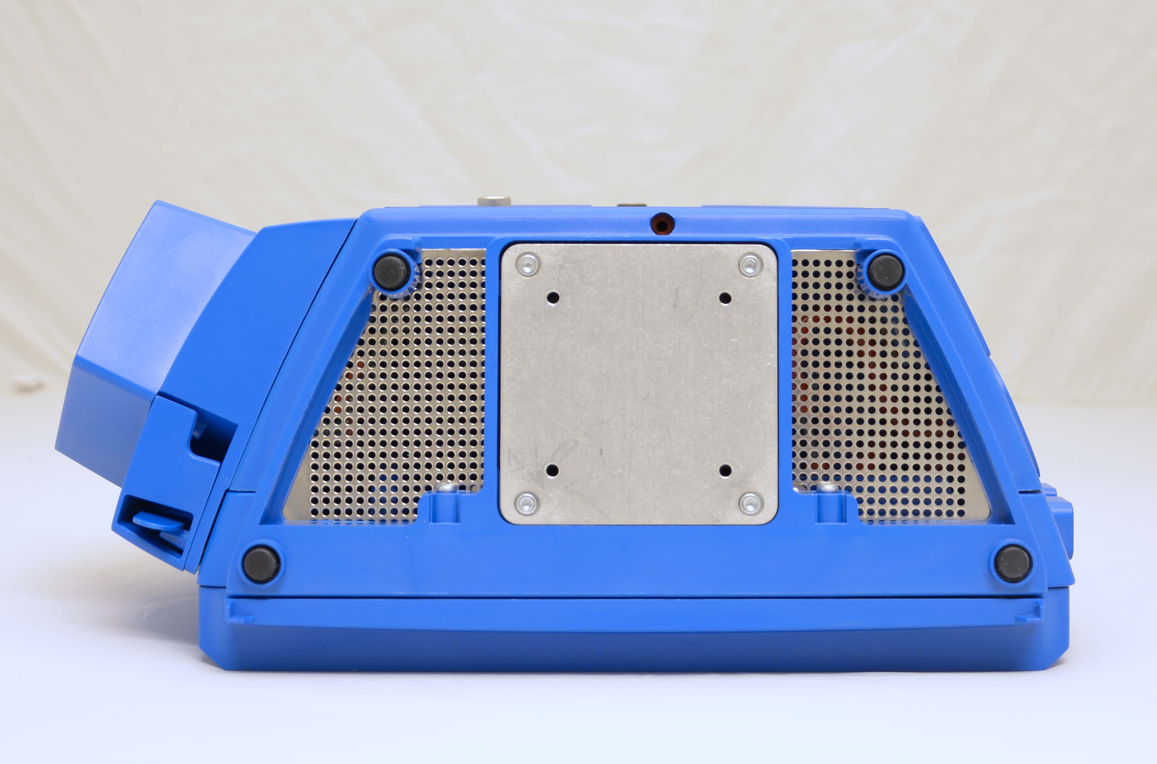
Click to zoom
Application Details
- Equipment Class
- NII - Unlicensed National Information Infrastructure TX
- Date of Grant
- Oct 16, 2014
- Application Purpose
- Original Equipment
- Date of Application
- Oct 14, 2014
- Equipment Note
- Patient Monitor
- Frequency Range
- 5500.00000000 - 5700.00000000
- Company
- Innokas Yhtyma Oy
- Country
- Finland
Documents & Files
Document Text
Text extracted from the exhibit documents filed with the FCC. Open a document above to read the original.
Users Manual
VC150 Vital Signs Monitor Operator’s Manual VC150 Vital Signs Monitor English KO00065K © 2014 Innokas Medical All rights reserved. LOW RESOLUTION PDF NOT FOR CUSTOMER PRINT! T-2VC150 Vital Signs MonitorKO00065K 30 September 2014 NOTE The information in this manual applies to VC150 Vital Signs Monitor. Due to continuing product innovation, specifications in this manual are subject to change without notice. Listed below are GE Medical Systems Information Technologies, Inc. trademarks. All other trademarks contained herein are the property of their respective owners. GE TruSignal is the property of GE Medical Systems Information Technologies, Inc., a division of General Electric Corporation. All other product and company names are the property of their respective owners. Description of NIBP algorithm © GE Medical Systems Information Technologies, Inc., reproduced by permission. DINAMAP, DURA-CUF, SOFT-CUF Blood Pressure Cuffs, and SuperSTAT are trademarks of GE Medical Systems Information Technologies, Inc. Welch Allyn ® and SureTemp ® Plus are registered trademarks of Welch Allyn, Inc. Exergen and TAT-5000S -USB are trademarks of Exergen Corporation. Betadine ® is a registered trademark of Purdue-Frederick. Masimo rainbow ® SET ® , LNOP, LNCS and Signal IQ are registered trademarks of Masimo Corporation. Possession or purchase of this device does not convey any express or implied license to use the device with unauthorized sensors or cables which would, alone or in combination with this device, fall within the scope of one or more of the patents relating to this device. Nellcor, OxiMax, C-LOCK and SatSeconds are trademarks of Covidien. Innokas Medical is a subsidiary of Innokas Yhtymä Oy. KO00065KVC150 Vital Signs Monitori Contents 1Introduction . . . . . . . . . . . . . . . . . . . . . . 1-1 About this device . . . . . . . . . . . . . . . . . . . . . . . . . . . . . . . . . . . . . . . . . . . . . . . . . 1-2 Intended use . . . . . . . . . . . . . . . . . . . . . . . . . . . . . . . . . . . . . . . . . . . . . . . . . . . . 1-3 Contraindications . . . . . . . . . . . . . . . . . . . . . . . . . . . . . . . . . . . . . . . . . . . . . . . . 1-4 Dangers, warnings, cautions, and notes . . . . . . . . . . . . . . . . . . . . . . . . . . . . 1-4 Safety precautions . . . . . . . . . . . . . . . . . . . . . . . . . . . . . . . . . . . . . . . . . . . . . . . 1-5 Product compliance . . . . . . . . . . . . . . . . . . . . . . . . . . . . . . . . . . . . . . . . . . . . 1-10 VC150 vital signs monitor . . . . . . . . . . . . . . . . . . . . . . . . . . . . . . . . . . . . . . . . . 1-10 Exergen temporal scanner . . . . . . . . . . . . . . . . . . . . . . . . . . . . . . . . . . . . . . . 1-12 Monitor symbols . . . . . . . . . . . . . . . . . . . . . . . . . . . . . . . . . . . . . . . . . . . . . . . 1-13 About this manual . . . . . . . . . . . . . . . . . . . . . . . . . . . . . . . . . . . . . . . . . . . . . 1-16 Service requirements . . . . . . . . . . . . . . . . . . . . . . . . . . . . . . . . . . . . . . . . . . . . . 1-17 2Product overview . . . . . . . . . . . . . . . . . 2-1 Front view . . . . . . . . . . . . . . . . . . . . . . . . . . . . . . . . . . . . . . . . . . . . . . . . . . . . . . . 2-2 Rear view and left side . . . . . . . . . . . . . . . . . . . . . . . . . . . . . . . . . . . . . . . . . . . . 2-2 Right side . . . . . . . . . . . . . . . . . . . . . . . . . . . . . . . . . . . . . . . . . . . . . . . . . . . . . . . 2-3 User interface and connections . . . . . . . . . . . . . . . . . . . . . . . . . . . . . . . . . . . . 2-4 Operating modes . . . . . . . . . . . . . . . . . . . . . . . . . . . . . . . . . . . . . . . . . . . . . . . . 2-9 Clinical mode . . . . . . . . . . . . . . . . . . . . . . . . . . . . . . . . . . . . . . . . . . . . . . . . . . . . 2-10 Monitor configuration . . . . . . . . . . . . . . . . . . . . . . . . . . . . . . . . . . . . . . . . . . . . 2-10 Printout . . . . . . . . . . . . . . . . . . . . . . . . . . . . . . . . . . . . . . . . . . . . . . . . . . . . . . . 2-14 Remote Management . . . . . . . . . . . . . . . . . . . . . . . . . . . . . . . . . . . . . . . . . . . 2-15 Battery low shutdown or system failure . . . . . . . . . . . . . . . . . . . . . . . . . . 2-15 Sounds . . . . . . . . . . . . . . . . . . . . . . . . . . . . . . . . . . . . . . . . . . . . . . . . . . . . . . . . 2-15 Battery charger sounds . . . . . . . . . . . . . . . . . . . . . . . . . . . . . . . . . . . . . . . . . . 2-15 Essential performance . . . . . . . . . . . . . . . . . . . . . . . . . . . . . . . . . . . . . . . . . . 2-16 Product specifications . . . . . . . . . . . . . . . . . . . . . . . . . . . . . . . . . . . . . . . . . . 2-19 Printer specifications . . . . . . . . . . . . . . . . . . . . . . . . . . . . . . . . . . . . . . . . . . . 2-21 Connectivity specifications . . . . . . . . . . . . . . . . . . . . . . . . . . . . . . . . . . . . . . 2-21 Open source software notice . . . . . . . . . . . . . . . . . . . . . . . . . . . . . . . . . . . . 2-23 KO00065KVC150 Vital Signs Monitorii 3Getting started . . . . . . . . . . . . . . . . . . . 3-1 Introduction . . . . . . . . . . . . . . . . . . . . . . . . . . . . . . . . . . . . . . . . . . . . . . . . . . . . . 3-2 Setting up NIBP connections . . . . . . . . . . . . . . . . . . . . . . . . . . . . . . . . . . . . . . 3-2 Setting up SpO 2 connections . . . . . . . . . . . . . . . . . . . . . . . . . . . . . . . . . . . . . . 3-4 Setting up temperature connection . . . . . . . . . . . . . . . . . . . . . . . . . . . . . . . . 3-4 Welch Allyn (optional) . . . . . . . . . . . . . . . . . . . . . . . . . . . . . . . . . . . . . . . . . . . . . 3-4 Connecting USB accessories . . . . . . . . . . . . . . . . . . . . . . . . . . . . . . . . . . . . . . 3-6 Installation/replacement of printer paper . . . . . . . . . . . . . . . . . . . . . . . . . . 3-6 Paper storage . . . . . . . . . . . . . . . . . . . . . . . . . . . …
Text truncated - open the document above for the full version.
Attestation Statements
SGS Fimko EMC Oy Perkkaantie 11 P.O. Box 19 FI-02601 Espoo t +358 (0)42 454 541 www.sgs.fi Member of the SGS Group (SGS SA) ATTESTATION of TEST SITE Test site address: Perkkaantie 11, P.O.BOX 19, FI-02601 Espoo, Finland FCC Reg. No. 359859 IC File No. 2040F-1 The test site referenced above has been listed by FCC and IC under the company name Nemko Oy. Nemko Oy has been acquired by SGS Finland on January 15, 2014. From that date the operator of the test site has been SGS Fimko EMC Oy. No other changes have been made in the test site. No changes in the personnel, nor in the measurement instrumentation have been taken. SGS Fimko EMC Oy
External Photos
VC150 External Photos Front Type label Back Right Left Top Bottom
Internal Photos
VC150 Internal Photos Isolation board, bottom, with isolation barrier Isolation board, top, with isolation barrier Isolation board, top, without isolation barrier Isolation board, bottom, without isolation barrier Isolation board, placement Medical USB board, top Medical USB board, bottom Medical USB board, placement Medical USB board, placement Motherboard, top Motherboard, bottom Motherboard, placement NIBP Board, top NIBP Board, bottom NIBP Board, placement
Internal Photos
NIBP Board, placement USB Board, top USB Board, bottom USB Board, placement Welch Allyn Board, top Welch Allyn Board, bottom Welch Allyn Board, placement Welch Allyn Board, placement TruSignal SpO2 Board, top TruSignal SpO2 Board, bottom Nellcor SpO2 Board, top Nellcor SpO2 Board, bottom Masimo SpO2 Board, top Masimo SpO2 Board, bottom TruSignal/Nellcor/Masimo SpO2 Board, placement
RF Exposure Info
1 (2) RF EXPOSURE Equipment Under Test (EUT) Vital Signs Monitor (WLAN) Type/ Model: FCC ID: IC: Project number: VC150 2ABKEVC150 11902A-VC150 277435 Standard applicable According to §1.1307(b)(1), systems operating under the provisions of this section shall be operated is a manner that ensure that the public is not exposed to radio frequency energy level in excess of the Commission’s guideline. This is a mobile device, the MPE is required. According to §1.1310 and §2.1093 RF exposure is calculated. Limits for Maximum Permissive Exposure (MPE) Frequency range (MHz) Electric field strength (V/m) Magnetic field strength (A/m) Power density (mW/cm 2 ) Averaging time (minutes) Limits for General Population/Uncontrolled Exposure 0.3-1.34 614 1.63 *100 30 1.34-30 824/f 2.19/f *180/f 2 30 30-300 27.5 0.073 0.2 30 300-1,500 f/1500 30 1,500-100,000 1.0 30 f = frequency in MHz * = Plane-wave equivalent power density 2/2 MPE Prediction Prediction of MPE limit at a given distance, equation from OET Bulletin 65, Edition 97-01 S = (PG)/(4πR 2 ) Where: S = power density P = power input to antenna G = power gain of the antenna in the direction of interest relative to an isotropic radiator R = distance to the center of radiation of the antenna MPE Results 5180 – 5805 MHz Maximum peak output power at antenna input terminal (dBm): 14.92 Maximum peak output power at antenna input terminal (mW): 31 Maximum antenna gain (dBi): 2.0 Maximum antenna gain (typical) (numerical): 1.58 Prediction distance (cm) 20 Prediction frequency (MHz) 5180 Power density of prediction frequency at 20.0 cm (mW/cm 2 ) 0.0097 MPE limit for uncontrolled exposure at prediction frequency (mW/cm 2 ) 1.0 Margin(dB) 20.1 Conclusion The predicted power density level at 20 cm is 0.0097 mW/cm 2 (5180 MHz) which is below the uncontrolled exposure limit of 1.0 mW/cm 2 . Date: SEP 12, 2014
Test Report
SGS Fimko EMC Oy Perkkaantie 11 P.O. Box 19 FI-02601 Espoo t +358 (0)42 454 541 www.sgs.fi Member of the SGS Group (SGS SA) TEST REPORT Date: ESPOO 01.04.2014 Page: 1 (53) Appendices Date of handing in: 31.10.2013 Number: 249312B No. 1 / 1 Tested by: Timo Hietala, Test Specialist Reviewed by: Timo Leismala, Test Manager SORT OF EQUIPMENT: Vital signs monitor MARKETING NAME: VC150 Vital Signs Monitor TYPE: VC150 MANUFACTURER: Innokas Medical CLIENT: Innokas Medical ADDRESS: Tarjusojantie 12, FI-90440 Kempele, FINLAND TELEPHONE: +358 8 562 3100 TEST LABORATORY: Nemko Oy FCC REG. NO. 359859 October 25, 2013 IC FILE NO. 2040F-1 November 22, 2012 SUMMARY: In regard to the performed tests the equipment under test fulfils the requirements defined in the test specifications, see page 2 for details The test results are valid for the tested unit only. Without a written permission of SGS Fimko EMC Oy it is allowed to copy this report as a whole, but not partially. Version f1.00 Type: VC150 Test report: 249312B Page 2 (53) Date 01.04.2014 Summary of performed tests and test results Test Section in CFR 47 Result 1 15.207 AC power line conducted emissions PASS, margin 3.5 dB 2 15.209 / 15.407 (b) Electric Field Strength Spurious Emissions, 30MHz ~ 40000MHz PASS, margin 3.3 dB 3 15.407 (a) 26dB Bandwidth PASS 4 15.407 (a) Maximum peak output power PASS 5 15.407 (a) Peak Power Spectral Density PASS 6 15.407 (a) Peak excurcion PASS 7 15.407 (b) Band Edge compliance PASS 8 15.407 (g) Frequency Stability PASS Explanations: PASS The EUT passed that particular test. FAIL The EUT failed that particular test. Disclaimer This test report is issued under SGS Fimko EMC general terms of delivery (available on request and accessible at www.fi.sgs.com). Attention is drawn to the limitations of liability, indemnification and jurisdictional issues defined therein. Unless otherwise stated: (a) the results shown in this document refer only to the sample(s) tested and (b) such sample(s) are retained for three months. This document cannot be reproduced except in full, without prior approval of SGS Fimko EMC. Any unauthorized alteration, forgery or falsification of the content or appearance of this report is unlawful and offenders may be prosecuted to the fullest extent of the law. Type: VC150 Test report: 249312B Page 3 (53) Date 01.04.2014 Contents Summary of performed tests and test results .......................................................................................... 2 1. EUT and Accessory Information ......................................................................................................... 4 1.1 EUT description ........................................................................................................................ 4 1.2 EUT and accessories ................................................................................................................ 5 2. Standards and measurement methods ............................................................................................... 6 2.1 AC power line conducted emissions ......................................................................................... 6 2.1.1 Test method and limit ............................................................................................................... 6 2.1.2 Test results ............................................................................................................................... 7 3. Test results .......................................................................................................................................... 9 3.1 Radiated emissions .................................................................................................................. 9 3.1.1 Test method and limit ............................................................................................................... 9 3.1.2 Test results ............................................................................................................................. 10 3.1.1 Test results ............................................................................................................................. 12 3.2 Maximum conducted peak output power ................................................................................ 14 3.2.1 Test method and limit ............................................................................................................. 14 3.2.2 Test results ............................................................................................................................. 15 3.3 26dB Bandwidth ...................................................................................................................... 22 3.3.1 Test method ............................................................................................................................ 22 3.3.2 Test results ............................................................................................................................. 22 3.4 Band-edge compliance ........................................................................................................... 29 3.4.1 Test method ............................................................................................................................ 29 3.4.2 Test results ............................................................................................................................. 30 3.5 Peak power spectral density ................................................................................................... 35 3.5.1 Test method and limit ............................................................................................................. 35 3.5.2 Test results ............................................................................................................................. 35 3.6 Peak power excursion ...............................................................…
Text truncated - open the document above for the full version.
Test Report
SGS Fimko EMC Oy Perkkaantie 11 P.O. Box 19 FI-02601 Espoo t +358 (0)42 454 541 www.sgs.fi Member of the SGS Group (SGS SA) Date: ESPOO 01.04.2014 Page: 1 (18) Appendices Date of handing in: 31.3.2014 Number: 249312C No. 1 / 1 Tested by: Timo Hietala, Test Specialist Reviewed by: Timo Leismala, Test Manager SORT OF EQUIPMENT: Vital Signs Monitor MARKETING NAME: VC150 Vital Signs Monitor TYPE: VC150 MANUFACTURER: Innokas Medical CLIENT: Innokas Medical ADDRESS: Tarjusojantie 12, FI-90440 Kempele, FINLAND TELEPHONE: +358 8 562 3100 TEST LABORATORY: SGS Fimko EMC Oy FCC REG. NO. 359859 October 25, 2013 IC FILE NO. 2040F-1 November 22, 2012 SUMMARY: In regard to the performed tests the equipment under test fulfils the requirements defined in the test specifications, see page 2 for details. The test results are valid for the tested unit only. Without a written permission of SGS Fimko EMC Oy it is allowed to copy this report as a whole, but not partially. Version f1.00 Type: VC150 Test report: 249312C Page 2 (18) Date 01.04.2014 Summary of performed tests and test results Section in CFR 47 Result 15.407 (h)(2) Dynamic Frequency Selection (DFS) PASS 1) 1) EUT type Client without radar detection. Explanations: PASS The EUT passed that particular test. FAIL The EUT failed that particular test. Disclaimer This test report is issued under SGS Fimko EMC general terms of delivery (available on request and accessible at www.fi.sgs.com). Attention is drawn to the limitations of liability, indemnification and jurisdictional issues defined therein. Unless otherwise stated: (a) the results shown in this document refer only to the sample(s) tested and (b) such sample(s) are retained for three months. This document cannot be reproduced except in full, without prior approval of SGS Fimko EMC. Any unauthorized alteration, forgery or falsification of the content or appearance of this report is unlawful and offenders may be prosecuted to the fullest extent of the law. Type: VC150 Test report: 249312C Page 3 (18) Date 01.04.2014 Contents Summary of performed tests and test results .......................................................................................... 2 1. EUT and Accessory Information ......................................................................................................... 4 1.1 EUT description ........................................................................................................................ 4 1.2 EUT and accessories ................................................................................................................ 4 2. Standards and measurement methods ............................................................................................... 5 2.1 Technical requirements for DFS in the 5250-5350 MHz and 5470-5725 MHz bands ............. 5 2.1.1 DFS Overview ........................................................................................................................... 5 2.1.2 Master Devices ......................................................................................................................... 6 2.1.3 Client Devices ........................................................................................................................... 6 2.1.4 DFS Detection Thresholds ........................................................................................................ 7 2.1.5 Response Requirements .......................................................................................................... 7 2.1.6 RADAR TEST WAVEFORMS .................................................................................................. 8 2.1.7 Short Pulse Radar Test Waveforms ......................................................................................... 8 2.1.8 Long Pulse Radar Test Waveform ........................................................................................... 9 3. Test results ........................................................................................................................................ 10 3.1 DFS ......................................................................................................................................... 10 3.1.1 Test method ............................................................................................................................ 10 3.1.2 Test data ................................................................................................................................. 11 4. List of test equipment ........................................................................................................................ 18 Type: VC150 Test report: 249312C Page 4 (18) Date 01.04.2014 1. EUT and Accessory Information 1.1 EUT description The EUT is a Vital Signs Monitor with WLAN unit. 1.2 EUT and accessories EUT, client: Type S/N SW VC150 SK513370003YP application version release 18.0 Master unit (Access point): Type S/N SW Cisco AIR-AP1131AG-E-K9 FCZ1613QXS 12.4 (10b)JDA3 FCC ID: LDK102054E Notebook: Type S/N HP Elitebook 8770w CNU305B55M Type: VC150 Test report: 249312C Page 5 (18) Date 01.04.2014 2. Standards and measurement methods The test were performed in guidance of the CFR 47 Part 15, 407 h 2.1 Technical requirements for DFS in the 5250-5350 MHz and 5470-5725 MHz bands 2.1.1 DFS Overview A U-NII network will employ a DFS function to: detect signals from radar systems and to avoid co-channel operation with these systems. provide on aggregate a Uniform Spreading of the Operating Channels across the entire band. This applies to the 5250-5350 MHz and/or 5470-5725 MHz bands. Within the context of the operation of the DFS function, a U-NII device will operate in either Master Mode or Client Mode. U-NII devices operating in Client Mode can only operate in a network controlled by a U-NII device operating in Master Mode. Tables 1 and 2 shown below summarize the information contained in sections 2.1.1 a…
Text truncated - open the document above for the full version.
Test Setup Photos
Type: VC150 S/N: - Appendix to Test report: 249312B Photographs Photograph 1. Radiated spurious emission test. Photograph 2. Conducted emissions at mains ports emission test.
Contact Information
Applicant
Tiina Kotipalo(Director of Quality and Regulatory Affairs)
Technical Contact
Non-Technical Contact
Innokas Yhtyma OyTiina Kotipalo
[email protected]358445623131
Test Firm
Nemko OyTimo Leismala
Technical Specifications
| # | Rule Parts | Frequency Range | Power Output |
|---|---|---|---|
| 3 | 15E | 5.50 GHz - 5.70 GHz | 20.00 mW |