2ABMZ-BR65V3-H-RT065-V3
BYROBOT Co., Ltd.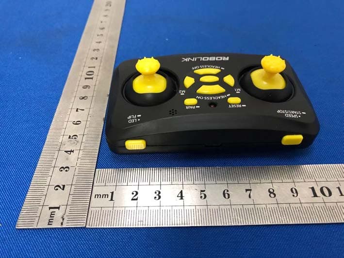
Click to zoom
Application Details
- Equipment Class
- DTS - Digital Transmission System
- Date of Grant
- Jan 09, 2020
- Application Purpose
- Original Equipment
- Date of Application
- Jan 09, 2020
- Equipment Note
- 65-V3
- Frequency Range
- 2402.00000000 - 2479.00000000
- Company
- BYROBOT Co., Ltd.
- Country
- South Korea
Documents & Files
Document Text
Text extracted from the exhibit documents filed with the FCC. Open a document above to read the original.
Users Manual
Disconnected ConnectedConnected 1. It is recommended that you use the product for users over the age of 8. It is recommended that first-time users be familiar with the manual and use it with sufficient practice. 2. The drone's propeller is so fast that it always requires attention and can cause physical and property damage. For your safety, always maintain a certain distance from the drone. 3. Manufacturers and vendors are not responsible for accidents due to poor operation. 4. Fly in normal weather conditions with temperatures between 50 °F and 122 °F. 5. For operational and repair inquiries, please contact your place of purchase. ● Make sure the battery is fully charged. ● Make sure the propeller is correctly installed. ● Make sure that the control and the drones are connected as normal. ● Make sure there are no obstructions in the area. ● Practice the drones first for take-off and landing and emergency stop functions. ● Use a distance of more than 2 meters from the drone. 1. Disconnect the battery out of the drone. The included charging via the charger usb. 2. charging, the charging is completed, and indicators illuminated indicator will extinguish. 1. Power On/Off / Reset Sensor Press and hold the power button in the middle of the controller for more than 3 seconds to turn it on and off. With the drone connected, press and hold the reset button to reset the sensor for the drone. 2. Throttle Lever & Directional Lever Once the drone is connected to the controller, it can begin to operate the drone For instructions on how to control each lever, see How to control a drone. 3. Trim Adjustment (F/B/L/R Button) & Mode 1/2 Change To stabilize a drone during flight if it is tilted in either front/rear/left/right direction: Press the F (front)/B (back)/L (left)/R (right) trim button to operate. You can change the mode using the L (left) and R (right) buttons when you are not in the flight 4. Speed · Start/Stop (SPEED · START / STOP) Press the button briefly to change the speed of the drone. (Step 1: Beep 1 / Step 2: Step 3) Press and hold the button for more than 3 seconds to automatically take off and land the drone. 5. Headless mode · pairing (HEADLESS · PAIR) When not in flight, press and hold the F button to activate the headless mode; press and hold B button to release. You can perform pairing by pressing and holding the PAIR button for more than 3 seconds when it is not in flight. 6. LED · Flip (LED · FLIP) Press the button briefly to change the LED on the drone to the desired color. During flight, when the LED · Flip button is pressed and the directional lever is moved, the drone rotates 360 degrees. 7. Status Indication When the drone is disconnected, the LEDs on the drone and the controller flash and beep. If the drone's battery is low, only the LEDs on the drone will flash and the controller will beep. Activate the 'headless mode' for beginners. The 'headless mode' is fixed in the direction of the drone's operation, regardless of the direction of the drone's front or rear. 'Headless mode' On when the LED on the controller flashes by pressing and holding the F button while landing 'Headless mode' off when the controller's LED illuminates brightly by pressing and holding the B button while landing. CAUTION: 'Headless mode' on/off can only be changed when landing; it cannot be changed during flight. When the headless mode is turned on by pressing the button, the direction the drone is facing is fixed forward. Settings allow you to change to mode1 or mode2. Pressing and holding the Ltrim button for more than 3 seconds while landing mode1 Pressing and holding the RTRIM button for more than 3 seconds while landing mode2 Caution: the default state is set to mode2 and if you change the mode, Be sure to familiarize yourself with the operation of that mode before flying. You can start/stop the motor when it is not in flight. Push both levers simultaneously as shown in the image and hold for at least 2 seconds. In the event of an emergency situation during flight, the emergency stop function can be used to stop the motor of the drone. Press and hold the speed start/stop button and press the throttle lever down to make an emergency stop. CAUTION: If the emergency stop function is used, the motor will stop and fall in the air, so the drone may be damaged. Only operate the function in an emergency. Be sure to familiarize yourself with the following methods before operating the drone. Poor steering requires a lot of practice because it can cause damage and injury. 1. Set the front and rear sides of the drone apart and place it on a flat. 2. Press the controller's automatic take-off/landing button for more than 3 seconds to initiate drone flight. * Make sure you have enough free space before turning 360 degrees. Press and hold the LED/FLIP button on the right side of the detector to hear a beep. Push the right-hand lever in the desired direction and the drone rotates 360 degrees in that direction. When the start button is pressed and held, the controller will continuously beep. 1. Place the drone on a flat surface and prepare for flight. 2. Press the automatic take-off/landing button of the controller for more than 3 seconds to take off. 3. The drone hovers. 4. During flight, press and hold the automatic take-off/landing button on the controller for more than 3 seconds to land. Please also be familiar with the emergency stop function in case of emergency. 1. Use the right-hand lever to slowly push forward/backward to practice front/backward control in the air. 2. Practice pushing the levers slowly to the left and right, as shown above. 1. Slowly raise the left throttle lever to maintain altitude in the air. 2. Adjust the throttle lever to maintain constant altitude and slowly slide the throttle lever to the left or right to rotate. If not in headless mode, the drone rotates and changes direction, so be aware of your flight. Once you are familiar with the preceding "practicing," practice your flight …
Text truncated - open the document above for the full version.
Cover Letter(s)
BYROBOT Co., Ltd. Agent Authorization Company: BYROBOT Co., Ltd. Address: A-#1001, Bundang Suji U-Tower, Sinsu-ro 767, Suji-gu Yongin-si, Gyeonggi-do South Korea 16827 Product Name: 65-V3 Model Number(s ): BR65V3-H-RT0 Product Description: 65-V3 We authorize MiCOM Labs Inc., 575 Boulder Court, Pleasanton, California 94566, USA, to act on our behalf on all matters concerning the certification of above named equipment. We declare that MiCOM Labs Inc. is allowed to forward all information related to the approval and certification of equipment to the regulatory agencies as required and to discuss any issues concerning the approval application. Any and all acts carried out by MiCOM Labs on our behalf shall have the same effect as acts of our own. Signature: Date: 2020/01/03 Name: Daehyun Oh Title: Manager Company: BYROBOT Co., Ltd.
Cover Letter(s)
BYROBOT Co., Ltd. Office of Engineering Technology Federal Communications Commission 7435 Oakland Mills Road Columbia, MD 21046 USA Date: 2020/01/03 Subject; Request for Confidentiality FCC ID: 2ABMZ-BR65V3-H -RT0 To Whom It May Concern, Pursuant to the provisions of the Commission’s rules Title 47 Sections §0.457 and §0.459, we are requesting the Commission to withhold the following attachment(s) as confidential documents from public disclosure indefinitely. These documents contain detailed system and equipment descriptions and are considered as proprietary information in operation of the equipment. The public disclosure of these documents might be harmful to our company and would give competitors an unfair advantage in the market. Schematic Diagram Block Diagram Operational Description In additional to above mentioned documents, in order to comply with the marketing regulations in Title 47 CFR §2.803 and the importation rules in Title 47 CFR §2.1204, while ensuring that business sensitive information remains confidential until the actual marketing of newly authorized devices, we request Short Term Confidentiality of the following attachment(s); User Manual For 45 days, pursuant to Public Notice DA 04-1705. OR For 180 days pursuantto KDB 726920 D01. It is our understanding that all measurement test reports, FCC ID label format and correspondence during the certification review process cannot be granted as confidential documents and this information will be available for public review once the grant of equipment authorization is issued. Sincerely, Signature: Name: Daehyun Oh Title: Manager
External Photos
External Photos
ID Label/Location Info
Size:20*10mm M/N: BR65V3-H-RT0 FCC ID: 2ABMZ-BR65V3-H-RT0 Label location
Internal Photos
Internal Photos Antenna
RF Exposure Info
RF EXPOSURE EVALUATION METHOD FCC ID: 2ABMZ-BR65V3-H-RT0 SAR Test Exclusion Thresholds for 100 MHz – 6 GHz and ≤ 50 mm Approximate SAR Test Exclusion Power Thresholds at Selected Frequencies and Test Separation Distances are illustrated in the following Table. The 1-g and 10-g SAR test exclusion thresholds for 100 MHz to 6 GHz at test separation distances ≤ 50 mm are determined by: [(max. power of channel, including tune-up tolerance, mW)/(min. test separation distance, mm)] · [√f(GHz)] ≤ 3.0 for 1-g SAR and ≤ 7.5 for 10-g extremity SAR,where f(GHz) is the RF channel transmit frequency in GHz Power and distance are rounded to the nearest mW and mm before calculation The result is rounded to one decimal place for comparison The test exclusions are applicable only when the minimum test separation distance is ≤ 50 mm and for transmission frequencies between 100 MHz and 6 GHz. When the minimum test separation distance is < 5 mm, a distance of 5 mm is applied to determine SAR test exclusion. BT-EDR max possible output power (PK,conducted):-7±1dbm 0dBi logarithmic terms convert to numeric result is nearly 1 -6dbm=0.25mW 2402MHz [(max. power of channel, including tune-up tolerance, mW)/(min. test separation distance,mm)] · [√f(GHz)]=0.25/5*√2.402 =0.08≤3.0 Threshold at which no SAR required is 10mw and ≤ 3.0 for 1-g SAR, Separation distance is 5mm. 2441MHz [(max. power of channel, including tune-up tolerance, mW)/(min. test separation distance,mm)] · [√f(GHz)]= 0.25/5*√2.441 =0.08≤3.0 Threshold at which no SAR required is 10mw and ≤ 3.0 for 1-g SAR, Separation distance is 5mm. Modulation Frequency (MHz) Output Power (dBm) Max Antenna Gain (dBi) GFSK 2402 -7.937 0 GFSK 2441 -7.703 0 GFSK 2479 -7.857 0 2480MHz [(max. power of channel, including tune-up tolerance, mW)/(min. test separation distance,mm)] · [√f(GHz)]=0.25/5*√2.48=0.08≤3.0 Threshold at which no SAR required is 10mw and ≤ 3.0 for 1-g SAR, Separation distance is 5mm. Conclusion: No SAR is required.
Test Report
Shenzhen BCTC Testing Co., Ltd. Report No.: BCTC1912001434E Test Report FCC ID: 2ABMZ-BR65V3-H -RT0 Product Name: 65-V3 Trademark: N/A Model Name : BR65V3-H-RT0 Prepared For : BYROBOT Co., Ltd. Address : A-#1001, Bundang Suji U-Tower, Sinsu-ro 767, Suji-gu Yongin-si, Gyeonggi-do South Korea 16827 Prepared By : Shenzhen BCTC Testing Co., Ltd. Address : BCTC Building & 1-2F, East of B Building, Pengzhou Industrial, Fuyuan 1st Road, Qiaotou Community, Fuyong Street, Bao’an District, Shenzhen, China Test Date: Dec. 16, 2019 – Dec. 25, 2019 Date of Report : Dec. 25, 2019 Report No.: BCTC1912001434E Te s t Report Tel: 400-788-9558 Web: https://www.bctc-lab.com BCTC/RF-EMC-0 07 Ver.:A.0 Page 1 of 42 Shenzhen BCTC Testing Co., Ltd. Report No.: BCTC1912001434E TEST RESULT CERTIFICATION Applicant’s name ................. : BYROBOT Co., Ltd. Address ................................. : A-#1001, Bundang Suji U-Tower, Sinsu-ro 767, Suji-gu Yongin-si, Gyeonggi-do South Korea 16827 Manufacture's Name ............ : BYROBOT Co., Ltd. Address ................................. : A-#1001, Bundang Suji U-Tower, Sinsu-ro 767, Suji-gu Yongin-si, Gyeonggi-do South Korea 16827 Product description Product name ........................... : 65-V3 Trademark ................................. : N/A Model and/or type reference : BR65V3-H-RT0 Standards ............................. : FCC Part15.247 ANSI C63.10:2013 KDB 558074 D01 15.247 Meas Guidance v05r02 This device described above has been tested by BCTC, and the test results show that the equipment under test (EUT) is in compliance with the FCC requirements. And it is applicable only to the tested sample identified in the report. This report shall not be reproduced except in full, without the written approval of BCTC, this document may be altered or revised by BCTC, personal only, and shall be noted in the revision of the document. Prepared by(Engineer): Willem Wang Reviewer(Supervisor): Eric Yang Approved(Manager): Zero Zhou Te s t Report Tel: 400-788-9558 Web: https://www.bctc-lab.com BCTC/RF-EMC-0 07 Ver.:A.0 Page 2 of 42 Shenzhen BCTC Testing Co., Ltd. Report No.: BCTC1912001434E Table of Contents Page 1 . SUMMARY OF TEST RESULTS 5 1.1 TEST FACILITY 6 1.2 MEASUREMENT UNCERTAINTY 6 2 . GENERAL INFORMATION 7 2.1 GENERAL DESCRIPTION OF EUT 7 2.2 DESCRIPTION OF TEST MODES 8 2.3 BLOCK DIGRAM SHOWING THE CONFIGURATION OF SYSTEM TESTED 9 2.4 DESCRIPTION OF SUPPORT UNITS(CONDUCTED MODE) 9 2.5 EQUIPMENTS LIST FOR ALL TEST ITEMS 10 3 . EMC EMISSION TEST 12 3.1 CONDUCTED EMISSION MEASUREMENT 12 3.1.1 POWER LINE CONDUCTED EMISSION LIMITS 12 3.1.2 TEST PROCEDURE 12 3.1.3 DEVIATION FROM TEST STANDARD 12 3.1.4 TEST SETUP 13 3.1.5 EUT OPERATING CONDITIONS 13 3.1.6 TEST RESULTS 14 3.2 RADIATED EMISSION MEASUREMENT 16 3.2.1 RADIATED EMISSION LIMITS 16 3.2.2 TEST PROCEDURE 17 3.2.3 DEVIATION FROM TEST STANDARD 17 3.2.4 TEST SETUP 18 3.2.5 EUT OPERATING CONDITIONS 19 3.2.6 TEST RESULTS (BETWEEN 9KHZ – 30 MHZ) 20 3.2.7 TEST RESULTS (BETWEEN 30MHZ – 1GHZ) 21 3.3 RADIATED BAND EMISSION MEASUREMENT 24 3.3.1 TEST REQUIREMENT: 24 3.3.2 TEST PROCEDURE 24 3.3.3 DEVIATION FROM TEST STANDARD 25 3.3.4 TEST SETUP 25 3.3.5 EUT OPERATING CONDITIONS 25 4 . POWER SPECTRAL DENSITY TEST 27 4.1 APPLIED PROCEDURES / LIMIT 27 4.1.1 TEST PROCEDURE 27 4.1.2 DEVIATION FROM STANDARD 27 Te s t Report Tel: 400-788-9558 Web: https://www.bctc-lab.com BCTC/RF-EMC-0 07 Ver.:A.0 Page 3 of 42 Shenzhen BCTC Testing Co., Ltd. Report No.: BCTC1912001434E Table of Contents Page 4.1.3 TEST SETUP 27 4.1.4 EUT OPERATION CONDITIONS 27 4.1.5 TEST RESULTS 28 5 . BANDWIDTH TEST 30 5.1 APPLIED PROCEDURES / LIMIT 30 5.1.1 TEST PROCEDURE 30 5.1.2 DEVIATION FROM STANDARD 30 5.1.3 TEST SETUP 30 5.1.4 EUT OPERATION CONDITIONS 30 5.1.5 TEST RESULTS 31 6 . PEAK OUTPUT POWER TEST 33 6.1 APPLIED PROCEDURES / LIMIT 33 6.1.1 TEST PROCEDURE 33 6.1.2 DEVIATION FROM STANDARD 33 6.1.3 TEST SETUP 33 6.1.4 EUT OPERATION CONDITIONS 33 6.1.5 TEST RESULTS 34 7 . 100 KHZ BANDWIDTH OF FREQUENCY BAND EDGE 35 7.1 APPLICABLE STANDARD 35 7.2 TEST PROCEDURE 35 7.3 DEVIATION FROM STANDARD 35 7.4 TEST SETUP 35 7.5 EUT OPERATION CONDITIONS 35 8 . ANTENNA REQUIREMENT 38 8.1 STANDARD REQUIREMENT 38 8.2 EUT ANTENNA 38 9 . EUT TEST PHOTO 39 10 . EUT PHOTO 41 APPENDIX-PHOTOGRAPHS OF EUT CONSTRUCTIONAL DETAILS Te s t Report Tel: 400-788-9558 Web: https://www.bctc-lab.com BCTC/RF-EMC-0 07 Ver.:A.0 Page 4 of 42 Shenzhen BCTC Testing Co., Ltd. Report No.: BCTC1912001434E 1. SUMMARY OF TEST RESULTS Test procedures according to the technical standards: RSS-247 Issue 2: February 2017 FCC Part15 (15.247) , Subpart C Standard Section Test Item Judgment Remark RSS-GEN 8.8 RSS-247 3.1 FCC Part15.207 Conducted Emission PASS RSS-247 5.2 (a) RSS-GEN 6.7 FCC Part 15.247 (a)(2) 6dB Bandwidth PASS RSS-247 5.4 (d) FCC Part 15.247 (b) Peak Output Power PASS RSS-247 5.5 FCC Part 15.247 (d) FCC Part 15.209 Radiated Spurious Emission PASS RSS-247 5.2 (b) FCC Part 15.247 (e) Power Spectral Density PASS RSS-Gen 8.10 FCC Part 15.205 Restricted Band of Operation PASS RSS-247 5.5. FCC Part 15.247(d) Band Edge (Out of Band Emissions) PASS RSS-GEN 6.8 FCC Part15.203 Antenna Requirement PASS NOTE: (1)” N/A” denotes test is not applicable in this Test Report Te s t Report Tel: 400-788-9558 Web: https://www.bctc-lab.com BCTC/RF-EMC-0 07 Ver.:A.0 Page 5 of 42 Shenzhen BCTC Testing Co., Ltd. Report No.: BCTC1912001434E 1.1 TEST FACILITY Shenzhen BCTC Testing Co., Ltd. Add.: BCTC Building & 1-2F, East of B Building, Pengzhou Industrial, Fuyuan 1st Road, Qiaotou Community, Fuyong Street, Bao’an District, Shenzhen, China FCC Test Firm Registration Number: 712850 IC Registered No.: 23583 1.2 MEASUREMENT UNCERTAINTY The reported uncertainty of measurement y ± U,where expended uncertainty U is based on a standard uncertainty multiplied by a coverage factor of k=2,providing a level of confidence of approximately 95 %。 No. Item Uncertainty 1 3m camber Radiated spurious emission(30MHz-1GHz) U=4.3dB 2…
Text truncated - open the document above for the full version.
Test Setup Photos
Shenzhen BCTC Testing Co., Ltd. Report No.: BCTC1912001434E 9. EUT TEST PHOTO Conducted Measurement Photos Te s t Report Tel: 400-788-9558 Web: https://www.bctc-lab.com BCTC/RF-EMC-0 07 Ver.:A.0 Page 39 of 42 Shenzhen BCTC Testing Co., Ltd. Report No.: BCTC1912001434E Radiated Measurement Photos Te s t Report Tel: 400-788-9558 Web: https://www.bctc-lab.com BCTC/RF-EMC-0 07 Ver.:A.0 Page 40 of 42
Contact Information
Applicant
Daehyun Oh(Manager)
Technical Contact
Test Firm
Shenzhen BCTC Testing Co., Ltd.Alan Mei
[email protected]+8675536882589
Technical Specifications
| # | Rule Parts | Frequency Range | Power Output |
|---|---|---|---|
| 1 | 15C | 2.40 GHz - 2.48 GHz | 170.00 µW |
Other Applications from BYROBOT Co., Ltd.

2ABMZ-DF-T01
Mar 25, 2014THE PRODUCT IS DRONE FIGHTER CONTROLLER
Equipment Class
DTS - Digital Transmission System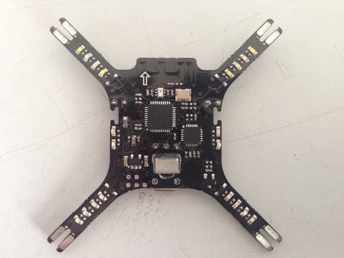
2ABMZ-DF-R01
Mar 25, 2014THE PRODUCT IS DRONE FIGHTER
Equipment Class
DTS - Digital Transmission System