2ABN2-ND04CBluetooth MODULE
ShenZhen RF-STAR Technology CO.,LTD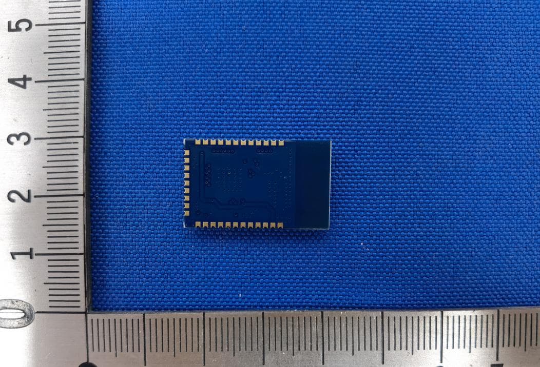
Click to zoom
Application Details
- Equipment Class
- DTS - Digital Transmission System
- Date of Grant
- Mar 15, 2021
- Application Purpose
- Original Equipment
- Date of Application
- Mar 11, 2021
- Equipment Note
- Bluetooth MODULE
- Frequency Range
- 2402.00000000 - 2480.00000000
- Country
- China
Documents & Files
Document Text
Text extracted from the exhibit documents filed with the FCC. Open a document above to read the original.
Users Manual
Shenzhen RF-star Technology Co.,Ltd. 1 RF-BM-ND04 RF-BM-ND04C(BLE)Module Thismoduleisdesignedtogettheelectronicproductstogetherwithintelligent ForthetransplantationanduseofBluetoothLowEnergy(BLE)applicationsinvarious industryproducts. SHENZHENRFSTARTECHNOLOGYCO.,LTDreleasesBLEtransparenttransmission module. Themodulemakethehostapplicationdevelopmenteasierasasabridgeofsmart phoneperipherals.User'sexistingproductsorsolutionswiththismodule,can communicatewithmobiledevices,realizeintelligentcontrolandmanagementunder thebridge(serialport)mode.Userscandesigntheirownsolutionsorproductsto usethemoduletoextendsimpleperipheralsunderthedirectdrivingmode,to releasenewperipheralsinlowestcostandefficiency. TheRF-BM-ND04CBLEmoduleuseNordicnRF52810asthecoreprocessorwith Nordicofficialstack,whichrunsat2.4GHzISMband,GFSK(GaussianFrequencyShift Keying)modulationmode,with40channelsin2MHzclearances,Modulesize 24.8*15*2.0mm. Features: 1.Convenient,dowithoutanyBluetoothprotocolstackapplicationexperience. 2.Usinguniversalserialtodesignusers’interfacewithbi-directionalreadingand simpleoperation 3.Dimensionalchanneldesign,minimizedatapacketprocessing,andmaximizethe communicationefficiency. 4.Ultralowpowerconsumptioninstandbymode. Applications: 2.4-GHzBluetoothlowenergySystems MobilePhoneAccessories SportsandLeisureEquipment HealthCareandMedicaluHomeandBuildingAutomation ConsumerElectronics Shenzhen RF-star Technology Co.,Ltd. 4 nRF52832QFAA 1.7V to 3.6V,typical 3. 3V 2402 MHz~2480MHz +4 dBm -96dBm 64KB 512KB ±20KHz -20°C -- +75°C (support -40°C~+85°C ) -40°C -- +85°C (support -40°C~+125°C ) GPIO:29 pcs working temperature: storage temperature: Shenzhen RF-star Technology Co.,Ltd. 5 Shenzhen RF-star Technology Co.,Ltd. 6 Pin1GND Pin2VCC 1.8~3.6V, 3.3V Pin3P21I/O Pin4P22I/O Pin5P23I/O Pin6P24I/O Pin7P25I/O Pin8P28I/O Pin9P29I/O Pin10P30I/O Pin11P26I/O Pin12P27I/O Pin13P02I/O Pin14P03I/O Pin15P04I/O Pin16P05I/O Pin17P06I/O Pin18P07I/O Pin19P08I/O Pin20P09I/O Pin21P10I/O Pin22P11I/O Pin23P12I/O Pin24P13I/O Pin25P14I/O Pin26P15I/O Pin27P16I/O Pin28SWDIO- Pin29SWCLK- Pin30P17I/O Pin31P18I/O Pin32P19I/O Pin33P20I/O Shenzhen RF-star Technology Co.,Ltd. 7 Shenzhen RF-star Technology Co.,Ltd. 8 图3 Shenzhen RF-star Technology Co.,Ltd. 9 modemintypicalmax power battery mode 1.73.33.6V operation temperature /-202575 °C environment temperature -2020 °C/minutes Shenzhen RF-star Technology Co.,Ltd. 10 FCC Statement FCC standards: FCC CFR Title 47 Part 15 Subpart C Section 15.247 Integral antenna with antenna gain 0 dBi This device complies with part 15 of the FCC Rules. Operation is subject to the following two conditions: (1) This device may not cause harmful interference, and (2) this device must accept any interference received, including interference that may cause undesired operation. Any Changes or modifications not expressly approved by the party responsible for compliance could void the user's authority to operate the equipment. Note: This equipment has been tested and found to comply with the limits for a Class B digital device, pursuant to part 15 of the FCC Rules. These limits are designed to provide reasonable pro tection against harmful interference in a residential installation. This equipment generates, uses and can radiate radio f requency energy and, if not installed and used in accordance with the instructions, may cause harmful interference to radio communications. However, there is no guarantee that interference will not occur in a p articular installation. If this equipment does cause harmful interference to radio or television reception, which can be determined by turning the equipment off and on, the user is encouraged to try to correct the interference by one or more of the following measures: —Reorient or relocate the receiving antenna. — Increase the separation between the equipment and receiver. — Connect the equipment into an outlet on a circuit different from that to which the receiver is connected. —Consult the dealer or an experienced radio/TV technician for help. FCC Radiation Exposure Statement This modular complies with FCC RF radiation exposure limits set forth for an uncontrolled environment. If the FCC identification number is not visible when the module is installed inside another device, then the outside of the device into which the module is installed must also display a label referring to the enclosed module. This exterior label can use wording such as the following: “Contains Transmitter Module FCC ID: 2ABN2-ND04C Or Contains FCC ID: 2ABN2-ND04C” When the module is installed inside another device, the user manual of the host must contain below warning statements; 1 . This device complies with Part 15 of the FCC Rules. Operation is subject to the following two conditions: (1) This device may not cause harmful interference; (2) This device must accept any interference received, including interference that may cause undesired operation. Note: This equipment has been tested and found to comply with the limits for a Class B digital device, pursuant to part 15 of the FCC Rules. These limits are designed to provide reasonable protection against harmful interference in a residential installation. This equipment generates, uses and can radiate radio frequency energy and, if not installed and used in accordance with the instructions, may cause harmful interference to radio communications. However, there is no guarantee that interference will not occur in a particular installation. If this equipment does cause harmful interference to radio or television reception, which can be determined by turning the equipment off and on, the user is encouraged to try to correct the interference by one or more of the following measures: —Reorient or relocate the receiving antenna. —Increase the separation between the equipment and receiver. —Connect the equipment into an outlet on a circuit different from that to which the receiver is connected. —Consult the dealer or an experienced radio/TV technician for help. …
Text truncated - open the document above for the full version.
Attestation Statements
Compliance list INTEGRATION INSTRUCTIONS for 996369 D03 OEM the and 996369 D03 OEM by Sections 2.2 through 2.10. Requirement Yes N/A Comment 2.2 List of applicable FCC rules List the FCC rules that are applicable to the modular transmitter. These are the rules that specifically establish the bands of operation, the power, spurious emissions, and operating fundamental frequencies. DO NOT list compliance to unintentional-radiator rules (Part 15 Subpart B) since that is not a condition of a module grant that is extended to a host manufacturer. See also Section 2.10 below concerning the need to notify host manufacturers that further testing is required.3 YES Refer to instruction F CC standards: FCC CFR Title 47 Part 15 Subpart C Section 15.247 2.3 Summarize the specific operational use conditions Describe use conditions that are applicable to the modular transmitter, including for example any limits on antennas, etc. For example, if point-to-point antennas are used that require reduction in power or compensation for cable loss, then this information must be in the instructions. If the use condition limitations extend to professional users, then instructions must state that this information also extends to the host manufacturer’s instruction manual. In addition, certain information may also be needed, such as peak gain per frequency band and minimum gain, specifically for master devices in 5 GHz DFS bands. YES Refer to instruction Integral antenna with antenna gain 0dBi 2.4 Limited module procedures If a modular transmitter is approved as a “limited module,” then the module manufacturer is responsible for approving the host environment that the limited module is used with. The manufacturer of a limited module must describe, both in the filing and in the installation instructions, the alternative means that the limited module manufacturer uses to verify that the host meets the necessary requirements to satisfy the module limiting conditions. A limited module manufacturer has the flexibility to define its alternative method to address the conditions that limit the initial approval, such as: shielding, minimum N/A Not applicable signaling amplitude, buffered modulation/data inputs, or power supply regulation. The alternative method could include that the limited module manufacturer reviews detailed test data or host designs prior to giving the host manufacturer approval. This limited module procedure is also applicable for RF exposure evaluation when it is necessary to demonstrate compliance in a specific host. The module manufacturer must state how control of the product into which the modular transmitter will be installed will be maintained such that full compliance of the product is always ensured. For additional hosts other than the specific host originally granted with a limited module, a Class II permissive change is required on the module grant to register the additional host as a specific host also approved with the module. 2.5 Trace antenna designs For a modular transmitter with trace antenna designs, see the guidance in Question 11 of KDB Publication 996369 D02 FAQ – Modules for Micro-Strip Antennas and traces. The integration information shall include for the TCB review the integration instructions for the following aspects: layout of trace design, parts list (BOM), antenna, connectors, and isolation requirements. 4 a) Information that includes permitted variances (e.g., trace boundary limits, thickness, length, width, shape(s), dielectric constant, and impedance as applicable for each type of antenna); b) Each design shall be considered a different type (e.g., antenna length in multiple(s) of frequency, the wavelength, and antenna shape (traces in phase) can affect antenna gain and must be considered); c) The parameters shall be provided in a manner permitting host manufacturers to design the printed circuit (PC) board layout; d) Appropriate parts by manufacturer and specifications; e) Test procedures for design verification; and N/A Not applicable f) Production test procedures for ensuring compliance. T he module grantee shall provide a notice that any deviation(s) from the defined parameters of the antenna trace, as described by the instructions, require that the host product manufacturer must notify the module grantee that they wish to change the antenna trace design. In this case, a Class II permissive change application is required to be filed by the grantee, or the host manufacturer can take responsibility through the change in FCC ID (new application) procedure followed by a Class II permissive change application. 2.6 RF exposure considerations It is essential for module grantees to clearly and explicitly state the RF exposure conditions that permit a host product manufacturer to use the module. Two types of instructions are required for RF exposure information: (1) to the host product manufacturer, to define the application conditions (mobile, portable – xx cm from a person’s body); and (2) additional text needed for the host product manufacturer to provide to end users in their end-product manuals. If RF exposure statements and use conditions are not provided, then the host product manufacturer is required to take responsibility of the module through a change in FCC ID (new application). YES Refer to instruction This modular complies with FCC RF radiation exposure limits set forth for an uncontrolled environment. 2.7 Antennas A list of antennas included in the application for certification must be provided in the instructions. For modular transmitters approved as limited modules, all applicable professional installer instructions must be included as part of the information to the host product manufacturer. The antenna list shall also identify the antenna types (monopole, PIFA, dipole, etc. (note that for example an “omni-directional antenna” is not considered to be a specific “antenna type”)). For situations where the host product manufacturer is responsible for an external …
Text truncated - open the document above for the full version.
Cover Letter(s)
SingleModularapprovalDeclarationletter We , ShenZhenRF-STARTechnologyCO.,LTD.applySinglemodularapprovalfor ProductName:BluetoothMODULE Model:RF-BM-ND04C FCCID:2ABN2-ND04C Accordingto996369D01ModuleEquipAuthGuidev01r04and15.212requirement: 1)Theradioelementsmusthavetheradiofrequencycircuitryshielded.Physical componentsandtuningcapacitor(s)maybelocatedexternaltotheshield,butmustbe onthemoduleassembly; Answer : Yes , Shieldedforbothside. 2)Themodulemusthavebufferedmodulation/datainputstoensurethatthedevice willcomplywithPart15requirementswithanytypeofinputsignal; Answer : Yes ; Allinputstothemodulesarebufferedthroughlogicormicroprocessor inputs. 3)Themodulartransmittermusthaveitsownpowersupplyregulation. Answer : Yes ; Alowdropoutregulatorisusedformodularpowersupplyregulation. 4)Themodulemustcontainapermanentlyattachedantenna,orcontainaunique antennaconnector,andbemarketedandoperatedonlywithspecificantenna(s),per Sections15.203,15.204(b),15.204(c),15.212(a),2.929(b); Answer : Yes ; DeviceisequippedwithPCBantenna. (5)Themodulemustdemonstratecomplianceinastand-aloneconfiguration; Answer : Yes , distancebetweenmodularandallAEsarebiggerthan10cm , referto setupphoto. (6)ThemodulemustbelabeledwithitspermanentlyaffixedFCCIDlabel,orusean electronicdisplay(SeeKDBPublication784748aboutlabelingrequirements); Answer : Yes ; Themodularhasapermanentfixedlabel,andbelowstatementwas listedintheUserManual;ThehostdevicemustbelabeledtodisplaytheFCCIDof themodule“ContainsFCCID:2ABN2-ND04C” (7)Themodulemustcomplywithallspecificrulesapplicabletothetransmitter includingalltheconditionsprovidedintheintegrationinstructionsbythegrantee; Answer : Yes ; Themodulecomplywithallspecificrulesapplicabletothe transmitterincludingalltheconditionsprovidedintheintegrationinstructionsby thegrantee,Refertotestreportandusermanual. (8)ThemodulemustcomplywithRFexposurerequirements Answer : Yes ; TransmittermeetsMPEcalculationofKDB447498.RefertoMPE ReportsandRefertomodularinstallationmanual Pleasecontactmeifyouhaveanyfurtherquestions.Thanksforyourattention. BestRegards,
External Photos
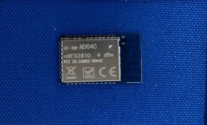
Model No.: RF-BM-ND04C
Internal Photos
Model No.: RF-BM-ND04C
RF Exposure Info
RF Exposure Evaluation Statement Product Name: Bluetooth MODULE Model No.:RF-BM-ND04C FCC ID:2ABN2-ND04C 1.1 RF Exposure Compliance Requirement 1.1.1 Standard Requirement According to KDB447498D01 General RF Exposure Guidance v06 Standalone SAR test exclusion considerations Unless specifically required by the published RF exposure KDB procedures, standalone 1-g head or body and 10-g extremity SAR evaluation for general population exposure conditions, by measurement or numerical simulation, is not required when the corresponding SAR Exclusion Threshold condition, listed below, is satisfied. 1.1.2 Limits The 1-g and 10-g SAR test exclusion thresholds for 100 MHz to 6 GHz at test separation distances ≤ 50 mm are determined by: [(max. power of channel, including tune-up tolerance, mW)/(min. test separation distance, mm)] · [√f(GHz)] ≤ 3.0 for 1-g SAR and ≤ 7.5 for 10-g extremity SAR, where f(GHz) is the RF channel transmit frequency in GHz Power and distance are rounded to the nearest mW and mm before calculation 17 The result is rounded to one decimal place for comparison The test exclusions are applicable only when the minimum test separation distance is ≤ 50 mm and for transmission frequencies between 100 MHz and 6 GHz. When the minimum test separation distance is < 5 mm, a distance of 5 mm is applied to determine SAR test exclusion 1.1.3 EUT RF Exposure Operational Mode: BLE Channel Maximum Peak Conducted Output Power (dBm) Tune up tolerance (dB) Maximum tune-up Power Calculated value Exclusion threshold (dBm) (mW) 2402MHz -1.56 ±1 -0.56 0.88 0.27 3.0 2442MHz -1.7 ±1 -0.7 0.85 0.27 2480MHz -2.09 ±1 -1.09 0.78 0.25 Conclusion: the calculated value ≤3.0, SAR is exempted.
Test Report
Page 1 of 64 BlueAsia of Technical Services(Shenzhen) Co., Ltd. Add: Building C, No. 107, Shihuan Road, Shiyan Sub-District, Baoan District, Shenzhen, Guangdong Province, China Tel: +86-755-23059481 Email: [email protected] www.cblueasia.com TEST REPORT Product Name : Bluetooth MODULE Brand Mark : RF-STAR Model No. : RF-BM-ND04C FCC ID : 2ABN2-ND04C Report Number : BLA-EMC-202102-A2901 Date of Sample Receipt : 2021/2/8 Date of Test : 2021/2/8 to 2021/2/23 Date of Issue : 2021/2/25 Test Standard : 47 CFR Part 15, Subpart C 15.247 Test Result : Pass Prepared for: ShenZhen RF-STAR Technology CO.,LTD 2F, BLDG.8,Zone A, BaoAn Internet Industry Base,BaoYuan Road, XiXiang, BaoAn DIST, ShenZhen China Prepared by: BlueAsia of Technical Services(Shenzhen) Co.,Ltd. Building C, No. 107, Shihuan Road, Shiyan Sub-District, Baoan District, Shenzhen, Guangdong Province, China TEL: +86-755-23059481 Compiled by: Review by: Approved by: Date: 2021/2/25 Report No.: BLA-EMC-202102-A2901 Page 2 of64 BlueAsia of Technical Services(Shenzhen) Co., Ltd. Tel: +86-755-23059481 Email: [email protected] www.cblueasia.com REPORT REVISE RECORD Version No. Date Description 00 2021/2/25 Original Report No.: BLA-EMC-202102-A2901 Page 3 of64 BlueAsia of Technical Services(Shenzhen) Co., Ltd. Tel: +86-755-23059481 Email: [email protected] www.cblueasia.com TABLE OF CONTENTS 1 TEST SUMMARY ........................................................................................................................................6 2 GENERAL INFORMATION .........................................................................................................................7 3 GENERAL DESCRIPTION OF E.U.T. .........................................................................................................7 4 TEST ENVIRONMENT ................................................................................................................................8 5 TEST MODE ................................................................................................................................................8 6 MEASUREMENT UNCERTAINTY ..............................................................................................................8 7 DESCRIPTION OF SUPPORT UNIT...........................................................................................................9 8 LABORATORY LOCATION .........................................................................................................................9 9 TEST INSTRUMENTS LIST ..................................................................................................................... 10 1 CONDUCTED EMISSIONS AT AC POWER LINE (150KHZ-30MHZ)..................................................... 14 1.1 LIMITS ................................................................................................................................................................... 14 1.2 BLOCK DIAGRAM OF TEST SETUP .......................................................................................................................... 14 1.3 PROCEDURE .......................................................................................................................................................... 14 1.4 TEST DATA .............................................................................................................................................................. 16 2 CONDUCTED BAND EDGES MEASUREMENT ..................................................................................... 18 2.1 LIMITS ................................................................................................................................................................... 18 2.2 BLOCK DIAGRAM OF TEST SETUP .......................................................................................................................... 18 2.3 TEST DATA .............................................................................................................................................................. 19 3 CONDUCTED PEAK OUTPUT POWER ................................................................................................. 20 3.1 LIMITS ................................................................................................................................................................... 20 3.2 BLOCK DIAGRAM OF TEST SETUP .......................................................................................................................... 20 3.3 TEST DATA .............................................................................................................................................................. 21 4 MINIMUM 6DB BANDWIDTH .................................................................................................................. 22 4.1 LIMITS ................................................................................................................................................................... 22 4.2 BLOCK DIAGRAM OF TEST SETUP .......................................................................................................................... 22 4.3 TEST DATA .............................................................................................................................................................. 22 5 ANTENNA REQUIREMENT ..................................................................................................................... 23 5.1 CONCLUSION ............................................................................................................................................................ 23 6 RADIATED SPURIOUS EMISSIONS ....................................................................................................... 24 Report No.: BLA-EMC-202102-A2901 Page 4 of64 BlueAsia of Technical Services(Shenzhen) Co., Ltd. Tel: +86-755-23059481 Email: marke…
Text truncated - open the document above for the full version.
Test Report
Report No.: BLA-EMC-202102-A2901 Page 61 of64 BlueAsia of Technical Services(Shenzhen) Co., Ltd. Tel: +86-755-23059481 Email: [email protected] www.cblueasia.com APPENDIX A: PHOTOGRAPHS OF TEST SETUP Conducted Emissions at AC Power Line (150kHz-30MHz) Radiated Spurious Emissions Report No.: BLA-EMC-202102-A2901 Page 62 of64 BlueAsia of Technical Services(Shenzhen) Co., Ltd. Tel: +86-755-23059481 Email: [email protected] www.cblueasia.com Report No.: BLA-EMC-202102-A2901 Page 63 of64 BlueAsia of Technical Services(Shenzhen) Co., Ltd. Tel: +86-755-23059481 Email: [email protected] www.cblueasia.com APPENDIX B: PHOTOGRAPHS OF EUT Report No.: BLA-EMC-202102-A2901 Page 64 of64 BlueAsia of Technical Services(Shenzhen) Co., Ltd. Tel: +86-755-23059481 Email: [email protected] www.cblueasia.com ----END OF REPORT---- The test report is effective only with both signature and specialized stamp, The result(s) shown in this report refer only to the sample(s) tested. Without written approval of BlueAsia, this report can’t be reproduced except in full.
Test Setup Photos
Model No.: RF-BM-ND04C
Contact Information
Applicant
Aroo woo
Test Firm
BlueAsia of Technical Services (Shenzhen)Blue Zheng
[email protected]+86 755-23059481-815
Technical Specifications
| # | Rule Parts | Frequency Range | Power Output |
|---|---|---|---|
| 1 | 15C | 2.40 GHz - 2.48 GHz | 698.00 µW |
Other Applications from ShenZhen RF-STAR Technology CO.,LTD
2ABN2-2340B1
Jan 22, 2024BLE Wireless Module
Equipment Class
DTS - Digital Transmission System
2ABN2-BG22A3
Dec 13, 2022BT module
Equipment Class
DTS - Digital Transmission System2ABN2-BG22B1
Jul 27, 2022BT module
Equipment Class
DTS - Digital Transmission System
2ABN2-BG22A1
Jan 17, 2021Bluetooth MODULE
Equipment Class
DTS - Digital Transmission System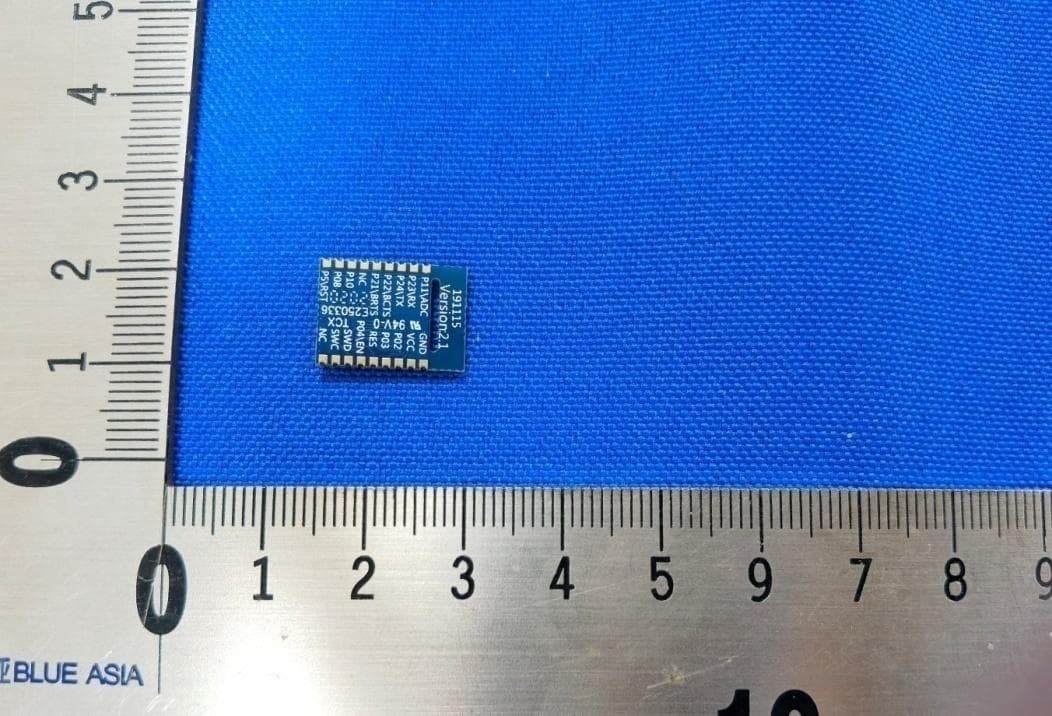
2ABN2-RSBRS02ABR
Nov 30, 2020Bluetooth module
Equipment Class
DTS - Digital Transmission System