2ABNQ-OST-NGEN-001Tire pressure monitoring system (TPMS)
TireStamp Inc.
Click to zoom
Application Details
- Equipment Class
- DSR - Part 15 Remote Control/Security Device Transceiver
- Date of Grant
- Jul 13, 2014
- Application Purpose
- Original Equipment
- Date of Application
- Jul 13, 2014
- Equipment Note
- Tire pressure monitoring system (TPMS)
- Frequency Range
- 433.92000000 - 433.92000000
- Company
- TireStamp Inc.
- Country
- Canada
Documents & Files
Document Text
Text extracted from the exhibit documents filed with the FCC. Open a document above to read the original.
Users Manual
©2014 TireStamp Inc. 1 Equipment Installation Manual Version 2.0 Rev A EQUIPMENT INSTALLATION MANUAL COMMERCIAL TIRE PRESSURE MONITORING SYSTEM Equipment Installation Manual ©2014 TireStamp Inc. 2 Equipment Installation Manual COMPONENT SPECIFICATIONS TDM InCab Display Operating Power Requirements: Operating Voltage 9V to 24V DC Avg. Power Consumption 0.5A at 12V DC Peak Power Consumption 2.0A at 12V DC Idle Power consumption 0.08A at 12V DC Operating Temperature: -40 o C to +85 o C (-40 o F to +185 o F) Dimensions 12.2 cm (W) x 2.5 cm (H) x 10..2 cm (D) 6” (W) x 1” (H) x 4” (D) Weight 241 g (8.5 oz.) RF Operating Frequency 433.92 MHz GSM/GPRS Frequency Quad Band EGSM 850 / 900 / 1800 / 1900 MHz No. of Monitored Tires Unlimited NHTSA TPMS Compatible YES Compliance/Certifications FCC/IC/CE/RCN and TPMS 2.0 OST Tire Sensor Transceiver Operating Voltage 9V to 24V DC Avg. Power Consumption 0.04 A at 12V DC Peak Power Consumption 0.10 A at 12V DC Operating Temperature: -40 o C to +85 o C (-40 o F to +185 o F) Dimensions 3.8 cm (W) x 6.3 cm (H) x 3.8 cm (D) 1.5” (W) x 2.5” (H) x 1.5” (D) Weight 70 g (2.4 oz.) RF Operating Frequency 433.92 MHz Compliance/Certifications FCC/IC/CE/RCN and TPMS 2.0 FCC and IC Notices This product complies with Part 15 Class B of the FCC rules and ICES-003 Part B of the Canadian EMI requirements. This product contains two device types, a TDM (Tire Data Monitor) and may contain one or more OST’s (Omni Sensor Transceivers). The FCC ID for the TDM device is 2ABNQ-TDM-NGEN-001 and contains FCCID RI7HE910NA. The FCC ID for OST device is 2ABNQ-OST-NGEN-001 Operation is subject to the following conditions: (1) This device cannot cause harmful interference; and (2) This device must accept any interference that may cause undesired operation. CAUTION: Changes or modifications to this unit not expressly approved by the party responsible for compliance could void the user’s authority to operate this equipment. This equipment has been tested and found to comply with the limits for a Class B digital device, pursuant to Part 15 of the FCC Rules. These limits are designed to provide reasonable protection against harmful interference in a residential installation. This equipment generates, uses and can radiate radio frequency energy and, if not installed and used in accordance with the manufacturer’s instructions, may cause interference harmful to radio communications. Equipment Installation Manual ©2014 TireStamp Inc. 3 Equipment Installation Manual There is no guarantee, however, that interference will not occur in a particular installation. If this equipment does cause harmful interference to radio or television reception, which can be determined by turning the equipment off and on, the user is encouraged to try to correct the interference by one or more of the following measures: - Reorient or relocate the receiving antenna. - Increase the separation between the equipment and receiver. Warning RF Exposure Compliance The antenna(s) used for this transmitter must be installed to provide a separation distance of at least 20 cm from all persons and must not be co-located or operating in conjunction with any other antenna or transmitter. Users and installers must be provided with antenna installation instructions and transmitter operating conditions for satisfying RF exposure compliance. FCC/Industry Canada Two Part Statement: This device complies with FCC Part 15 and Industry Canada license exempt RSS standards. Per Industry Canada RSS rules: This device complies with Health Canada’s Safety Code. The installer of this device should ensure that RF radiation is not emitted in excess of the Health Canada’s requirement. French/Francais Cet appareil est conforme à FCC Partie15 d’Industrie Canada RSS standard exempts de licence (s). Son utilisation est soumise à Les deux conditions suivantes: (1) cet appareil ne peut pas provoquer d’interférences et (2) cet appareil doit accepter Toute interférence, y compris les interférences qui peuvent causer un mauvais onctionnement du dispositif. Cet appareil est conforme avec Santé Canada Code de sécurité 6. Le programme d’installation de cet appareil doit s’assurer que les rayonnements RF n’est pas émis au- delà de I’exigence de Santé Canada. "Les changements ou modifications non expressément approuvés par la partie responsable de la conformité pourraient annuler l'autorité de l'utilisateur à utiliser cet équipement." AVERTISSEMENT EXPOSITION AUX RF Une distance d’au moins 20 cm doit être maintenue entre l’opérateur et l’appareil lorsque ce dernier est en fonctionnement. L’appareil ne doit pas être placée à proximité immediate d’une autre antenne ou un autre émetteur-récepteur. Other TireVigil™ TPMS system certifications are pending. Equipment Installation Manual ©2014 TireStamp Inc. 4 Equipment Installation Manual TireVigil™ TPMS Components Each TireVigil™ TPMS kit includes: One In-Cab Tire Data Monitor (TDM) Display OST transceivers to support up to 3 axles* TDM and OST Power Connectors Your Monitoring subscription includes: 24/7 Alerts, Reports and Servicing APP Vehicle Location awareness Vehicle Communications *Additional Axle Kits can be purchased separately †TPMS tire sensors sold separately In-Cab Display The OSTs In-Cab Tire Data Monitor (TDM) Display Lamp Indicators Definitions: Safety Warning Lamps In-Cab Display Lamps: 1. NHTSA Telltale Lamp: A YELLOW NHTSA compatible TPMS indicator lamp and 2. TireVigil™ Lamp: An AMBER Alert or RED Catastrophic ALERT indicator lamp. Acknowledgement (ACK) Pad Equipment Installation Manual ©2014 TireStamp Inc. 5 Equipment Installation Manual Installation Tools 1 Each OST requires a Deutsch DT connector, or equivalent, to connect to vehicle power. This connector must be properly crimped using a Deutsch Crimping Tool, Model HDT-48-00, or equivalent. 2 Digital Voltage meter or Test Lamp. 3 Pliers, wire cutters, screw drivers, a power drill, in-line fuses (1 Amp and 3 Amp) may be required and oth…
Text truncated - open the document above for the full version.
ID Label/Location Info
LABEL A LABEL B
RF Exposure Info
ONE WORLD OUR APPROVAL Nemko Canada Inc., 303 River Road, Ottawa, Ontario, Canada K1V 1H2 Tel: +1 (613) 737 9680, Fax: +1 (613) 737 9691, Email : [email protected] RSS-102 Issue 4, May 2013 www.nemko.com RSS-102, Issue 4 1 - Annex C, Declaration of RF exposure compliance for exemption from routine evaluation limits Company number: 11636A Model number: OST-NGEN-001 Manufacturer: TireStamp Inc. 2.5.1 SAR evaluation: SAR evaluation is required if the separation distance between the user and the radiating element of the device is less than or equal to 20 cm, except when the device operates as follows: ☐ from 3 kHz up to 1 GHz inclusively, and with output power (i.e. the higher of the conducted or equivalent isotropically radiated power (e.i.r.p.) source-based, time-averaged output power) that is less than or equal to 200 mW for general public use and 1000 mW for controlled use; ☐ above 1 GHz and up to 2.2 GHz inclusively, and with output power (i.e. the higher of the conducted or radiated (e.i.r.p.) source-based, time-averaged output power) that is less than or equal to 100 mW for general public use and 500 mW for controlled use; ☐ above 2.2 GHz and up to 3 GHz inclusively, and with output power (i.e. the higher of the conducted or radiated (e.i.r.p.) source-based, time-averaged output power) that is less than or equal to 20 mW for general public use and 100 mW for controlled use; ☐ above 3 GHz and up to 6 GHz inclusively, and with output power (i.e. the higher of the conducted or radiated (e.i.r.p.) source-based, time-averaged output power) that is less than or equal to 10 mW for general public use and 50 mW for controlled use. 2.5.2 RF exposure evaluation: RF exposure evaluation is required if the separation distance between the user and the device's radiating element is greater than 20 cm, except when the device operates as follows: ☒ below 1.5 GHz and the maximum e.i.r.p. of the device is equal to or less than 2.5 W; ☐ at or above 1.5 GHz and the maximum e.i.r.p. of the device is equal to or less than 5 W. E.i.r.p. calculation: Power = XXX dBm, Antenna gain: YYY dBi e.i.r.p.[W] = [ ] [ ] = = XXX mW < XXX W (RF exposure evaluation is not applicable) Measured peak field strength is 67.61dBμV/m @ 3 m.e.i.r.p.[W] = -27.62 dBm = 0.0017 mW < 200 mW (SAR and RF exposure evaluations are not applicable) E = field strength [V/m] R = distance [m] 2 – Attestation ATTESTATION: I attest that the radiocommunication apparatus meets the exemption from the routine evaluation limits in Section 2.5 of this standard; that the Technical Brief was prepared and the information contained therein is correct; that the device evaluation was performed or supervised by me; that applicable measurement methods and evaluation methodologies have been followed; and that the device meets the SAR and/or RF field strength limits of RSS-102. Signature: Date: June 11, 2014 Name: Kevin Rose, Wireless/EMC Specialist Company: Nemko Canada Inc. RF Exposure compliance
Test Report
Nemko Canada Inc., a testing laboratory, is accredited by the Standards Council of Canada. The tests included in this report are within the scope of this accreditation www.nemko.com FCC and IC 433 MHz.docx; Date: June, 2013 SCC Accredited LAB LAB Accrédité CCN TM ONE WORLDOURAPPROVAL Test report 248160-3TRFWL Date of issue: July 7, 2014 Applicant: TireStamp Inc. Product: TireVigil™ Tire Data Monitoring Model: OST-NGEN-001 FCC ID: IC Registration number: 2ABNQ-OST-NGEN-001 11636A-OSTNGEN001 Specifications: FCC 47 CFR Part 15, Subpart C, Chapter 15.231 Periodic operation in the band 40.66–40.70 MHz and above 70 MHz RSS-210, Issue 8 Annex 1.1 Momentarily operated devices Report reference ID: 248160-3TRFWL Page 2 of 23 Test location Company name: Nemko Canada Inc. Address: 303 River Road City: Ottawa Province: Ontario Postal code: K1V 1H2 Country: Canada Telephone: +1 613 737 9680 Facsimile: +1 613 737 9691 Toll free: +1 800 563 6336 FCC site ID: 176392 IC site ID: 2040A Website: www.nemko.com Tested by: Kevin Rose, Wireless/EMC Specialist Reviewed by: Andrey Adelberg, Senior Wireless/EMC Specialist Date: July 7, 2014 Signature: Limits of responsibility Note that the results contained in this report relate only to the items tested and were obtained in the period between the date of initial receipt of samples and the date of issue of the report. This test report has been completed in accordance with the requirements of ISO/IEC 17025. All results contain in this report are within Nemko Canada’s ISO/IEC 17025 accreditation. Copyright notification Nemko Canada Inc. authorizes the applicant to reproduce this report provided it is reproduced in its entirety and for use by the company’s employees only. Any use which a third party makes of this report, or any reliance on or decisions to be made based on it, are the responsibility of such third parties. Nemko Canada Inc. accepts no responsibility for damages, if any, suffered by any third party as a result of decisions made or actions based on this report. © Nemko Canada Inc. Report reference ID: 248160-3TRFWL Page 3 of 23 Table of Contents Table of Contents .......................................................................................................................................................................................... 3 Section 1 Report summary .................................................................................................................................................................... 4 1.1 Manufacturer ..................................................................................................................................................................................... 4 1.2 Applicant ........................................................................................................................................................................................... 4 1.3 Test specifications ............................................................................................................................................................................ 4 1.4 Statement of compliance ................................................................................................................................................................... 4 1.5 Test report revision history ................................................................................................................................................................ 4 Section 2 Summary of test results ........................................................................................................................................................ 5 2.1 FCC Part 15 Subpart C – Intentional Radiators, test results .............................................................................................................. 5 2.2 RSS-210, Issue 8 Annex 1.1, test results .......................................................................................................................................... 5 Section 3 Equipment under test (EUT) details ..................................................................................................................................... 6 3.1 Sample information ........................................................................................................................................................................... 6 3.2 EUT information ................................................................................................................................................................................ 6 3.3 EUT technical specifications ............................................................................................................................................................. 6 3.4 Operation of the EUT during testing .................................................................................................................................................. 6 3.5 EUT setup details .............................................................................................................................................................................. 7 Section 4 Engineering considerations ................................................................................................................................................. 8 4.1 Modifications incorporated in the EUT ............................................................................................................................................... 8 4.2 Technical judgment ........................................................................................................................................................................... 8 4.3 Deviations from laboratory tests procedures ..................................................................................................................................... 8 Section 5 Test condition…
Text truncated - open the document above for the full version.
Test Setup Photos
www.nemko.com Nemko Canada Inc., a testing laboratory, is accredited by the Standards Council of Canada. The tests included in this report are within the scope of this accreditation setup photos.docx; Date: May 2013 SCC Accredited LAB LAB Accrédité CCN TM ONE WORLDOURAPPROVAL Setup photos 248160-3RADWL Date of issue: December 10, 2013 Applicant: TireStamp Inc. Product: TireVigil™ Tire Data Monitoring Model: Tire Data Monitor (TDM) G4 Omni Sensor Transceiver (OST) V4 FCC ID: IC Registration number: Section 1: Setup photos Report reference ID: 248160-3RADWL Page 2 of 3 Section 1. Internal photos 1.1 Front view Section 1: Setup photos Report reference ID: 248160-3RADWL Page 3 of 3 1.2 Rear view
Contact Information
Applicant
Scott Feagan(CEO)
Technical Contact
Non-Technical Contact
Nemko CanadaJenny Gibbs
Test Firm
Nemko Canada Inc. (Ottawa)Charles Neal
Technical Specifications
| # | Rule Parts | Frequency Range | Power Output |
|---|---|---|---|
| 1 | 15.231,15.231(e) | 433.92 MHz - 433.92 MHz | - |
Other Applications from TireStamp Inc.
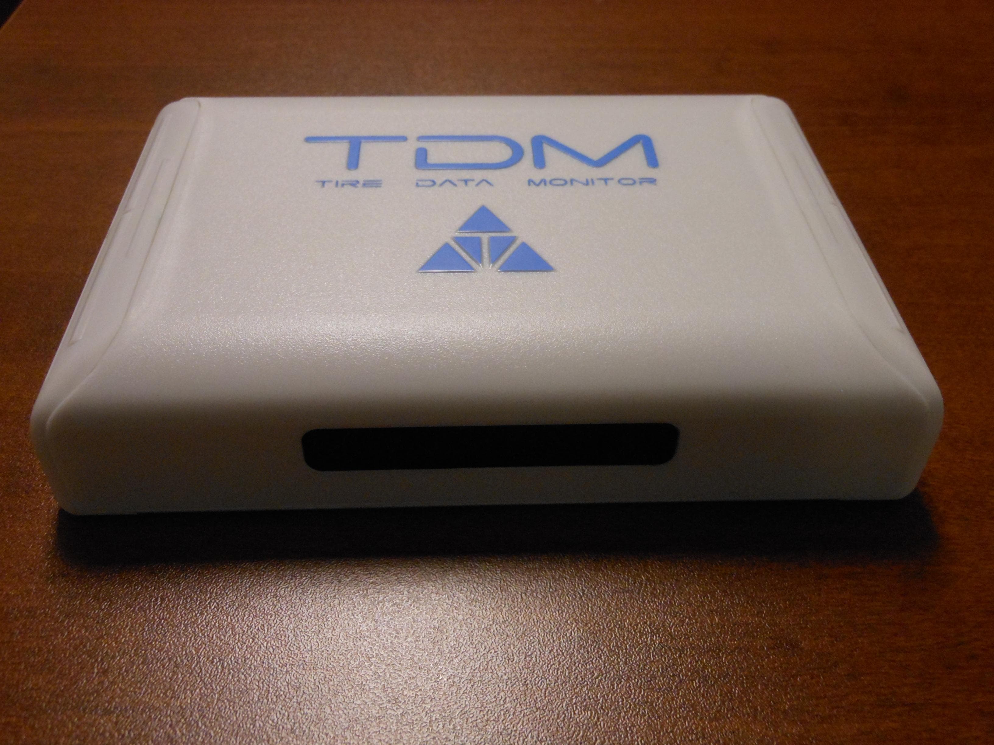
2ABNQ-TDM-NGEN-001
Jul 13, 2014Tire Data Monitor (TDM)
Equipment Class
DSR - Part 15 Remote Control/Security Device Transceiver