2ABOFAA22GAbsoluteAir 2 Family Wireless backhaul
Tarana Wireless, Inc.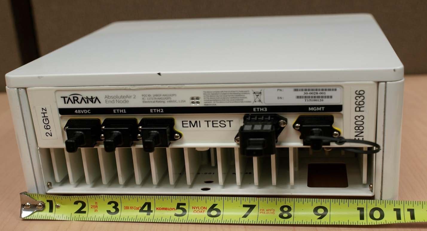
Click to zoom
Application Details
- Equipment Class
- TNB - Licensed Non-Broadcast Station Transmitter
- Date of Grant
- Nov 23, 2015
- Application Purpose
- Original Equipment
- Date of Application
- Nov 23, 2015
- Equipment Note
- AbsoluteAir 2 Family Wireless backhaul
- Frequency Range
- 2510.00000000 - 2680.00000000
- Company
- Tarana Wireless, Inc.
- Country
- United States
Documents & Files
Document Text
Text extracted from the exhibit documents filed with the FCC. Open a document above to read the original.
Users Manual
AbsoluteAir 2 Manual June 2015 ©2015 Tarana Wireless, Inc. All rights reserved 2953 Bunker Hill Lane, Suite 100 Santa Clara, CA 95054 USA www.taranawireless.com [email protected] Rocket science inside. Unrivaled performance outside. Tarana Wireless — AbsoluteAir 2 Manual Page 2 of 22 Tarana Wireless AbsoluteAir User Guide This user guide incorporates features and functions provided with Tarana's AbsoluteAir 2 products. Copyright © 2015 by Tarana Wireless All rights reserved. No part of this publication may be reproduced, transmitted, transcribed, stored in a retrieval system, or translated into any language or computer language, in any form or by any means, electronic, magnetic, optical, chemical, manual or otherwise, without the prior written permission of Tarana Wireless. To request permission, contact [email protected]. Warranty Tarana Wireless makes no representation or warranties with respect to the contents hereof and specifically disclaims any implied warranties or merchantability or fitness for any particular purpose. Further, Tarana Wireless reserves the right to revise this publication and to make changes from time to time in the content hereof without obligation of Tarana Wireless to notify any person of such revision or changes. Trademarks All trademarks are the property of their respective owners. Contact Information Sales and Sales Support: Contact Tarana Wireless headquarters, or find your regional sales office at http://www.taranawireless.com/contact. Tarana Wireless 2953 Bunker Hill Lane, Suite 100 Santa Clara, CA 95054 USA +1. 408.351.4085 Tarana Wireless — AbsoluteAir 2 Manual Page 3 of 22 Table of Contents 1 Warnings and Safety Information .............................................................................................................. 4 1.1 General Warnings ................................................................................................................................ 4 1.2 Health and Safety Warning ................................................................................................................. 4 1.3 Warning Labels .................................................................................................................................... 7 2 Package Contents ....................................................................................................................................... 8 3 Product Overview ....................................................................................................................................... 9 3.1 Deployment Configuration ................................................................................................................. 9 3.2 Non-‐Line-‐of-‐Sight, Point-‐to-‐Multipoint Backhaul ............................................................................. 10 3.3 Frequency Bands and Frequency Reuse ........................................................................................... 10 3.4 Key Applications ................................................................................................................................ 10 4 Deployment Overview .............................................................................................................................. 11 4.1 Electrical Power ................................................................................................................................. 11 4.2 Power and Data Options ................................................................................................................... 12 5 Pre-‐Provisioning ....................................................................................................................................... 14 5.1 Required Information for Pre-‐Provisioning ...................................................................................... 14 5.2 Pre-‐Provision Using the Command Line Interface ........................................................................... 14 6 Quick Install .............................................................................................................................................. 16 6.1 Verify That Tools are Available ......................................................................................................... 16 6.2 Check Package Contents ................................................................................................................... 17 6.3 Mount the Unit .................................................................................................................................. 17 6.4 Connect Data Cables and Power Up ................................................................................................. 20 7 Regulatory Information ............................................................................................................................ 21 7.1.1 Deployment in the US – FCC Statement .................................................................................... 21 7.1.2 Deployment in Canada -‐ Industry Canada Statements ............................................................. 21 Tarana Wireless — AbsoluteAir 2 Manual Page 4 of 22 1 Warnings and Safety Information 1.1 General Warnings Failure to observe these safety precautions may result in personal injury or damage to equipment. • Follow all warnings and instructions marked on this product. • Use standard safety guidelines when mounting. Installation and maintenance procedures must be followed and performed by trained personnel only. • Before unmounting the product, disconnect power input to reduce the risk of hazards. • Do not exceed 60V of input. • Do not open the device. Opening the device voids the warranty. • Do not stack anything on the radome. • Dust covers must be installed on all connectors when not in use. • Cable ends must be protected from weather if not connected to the device. • This is a Class 1 laser pr…
Text truncated - open the document above for the full version.
Cover Letter(s)
1 Federal Communications Commission Equipment Authorization Branch 7435 Oakland Mills Road Columbia, MD 21046 November 1st, 2015 Request for Confidentiality Company Name: Tarana Wireless FCC ID: 2ABOFAA22G Re: AbsoluteAir2 Family Gentlemen, In accordance with 0.457 and 0.459 of CFR 47, Tarana Wireless, Inc. hereby requests Sort term confidentiality of 180 days for the following documents for the subject application. External Photos User Manual These documents contain detailed system and equipment description and related information about the product which Tarana Wireless considers to be proprietary, confidential and a custom design and otherwise would not release to the general public. Since our product will not be marketed and will not be accessible to the general public, Tarana Wireless considers that this information would be of benefit to its competitors and that the disclosure of the information in these documents would give competitors an unfair advantage in the market. Sincerely, _____________________________ Signature Ivaylo Tankov Sr. Compliance Manager Tarana Wireless, Inc. 2953 Bunker Hill Line Santa Clara CA 95054 Email [email protected]; Ph: 408 351 4085x.156
Cover Letter(s)
1 Federal Communications Commission Equipment Authorization Branch 7435 Oakland Mills Road Columbia, MD 21046 November 1st, 2015 Request for Confidentiality Company Name: Tarana Wireless FCC ID: 2ABOFAA22G Re: AbsoluteAir2 Family Gentlemen, In accordance with 0.457 and 0.459 of CFR 47, and KDB 726920, Tarana Wireless, Inc. hereby requests permanent confidentiality of the following document for the subject application. Internal Photos Schematics Block Diagram Theory of Operation Bill of Materials The document above contain detailed system and equipment information about the product which Tarana Wireless considers to be proprietary, confidential and a custom design and otherwise would not release to the general public. Since our product will not be marketed and will not be accessible to the general public, Tarana Wireless considers that this information would be of benefit to its competitors and that the disclosure of the information in these documents would give competitors an unfair advantage in the market. In addition our products are installed by professional installers and at areas not accessible to the public. NDA will be in place for each purchase with the owner of the equipment and license holder, and the technical staff responsible for initial installation and maintenance. Internal Photos are only provided to FCC as part of Certification process. Each unit is mounted at location not accessible to the general public serviceable only by designated professional technical personal. Disassembly of the product is restricted by being secured with special tamperproof screws. Sincerely, _____________________________ Ivaylo Tankov Sr. Compliance Manager Tarana Wireless, Inc. 2953 Bunker Hill Line Santa Clara CA 95054 Email [email protected]; Ph: 408 351 4085
Cover Letter(s)
1 Letter of Authorization November 1st, 2015 To Whom It My Concern Re: AbsoluteAir2 Family Models We undersigned Tarana Wireless Inc, 2953 Bunker Hill Line Santa Clara CA 95054 USA, authorize MiCOM Labs, 575 Boulder Court, Pleasanton CA 94566 USA, to act on our behalf on all matters concerning the above named equipment. This shall include the following: - Testing - Approval applications and procedures - Payment of approval fees We declare that MiCOM Labs, 575 Boulder Court, Pleasanton, CA 94566, USA, is allowed to forward all information related to the approval process for this project to engaged Regulatory Authorities, Notified Bodies, Notification Entities and to discuss any issues concerning the approval application. Any and all acts carried out by MiCOM Labs on our behalf shall have the same effect as acts of our own. This Letter of Authorization is valid for 180 days since the date above. Sincerely, _____________________________ Signature Ivaylo Tankov Sr. Compliance Manager Tarana Wireless, Inc. 2953 Bunker Hill Line Santa Clara CA 95054 Email [email protected]; Ph: 408 351 4085x.156
External Photos
1 External Photos for AbsoluteAir2 Family Photo 1‐ Bottom View with Connectors Photo 2‐ Back View Side Antenna Panels mounted over the enclosure Side Antenna Panels mounted over the enclosure 2 Photo 3‐ Top View with GPS Antenna (mounted on ALL Models) Photo 4‐ Side View – Antennas on both sides are identical
ID Label/Location Info
The device complies with Part 15 of the FCC Rules and IC Regulations. Operation is subject to the following conditions: This device (1) may not cause harmful interference; (2) must accept any interference received, including interference that may cause undesired operation; and (3) must be professionally installed. Made in U.S.A. AbsoluteAir 2 Edge Node ETH140-60 VDC 1.5AETH 2ETH3MGMT FCC ID: 2ABOFAA22G IC: 11717A-AA22G EN & RN AbsoluteAir 2 Concentrator Node 40-60VDC 1.5AETH1ETH2ETH3MGMT FCC ID: 2ABOFAA22G IC: 11717A-AA22G The device complies with Part 15 of the FCC Rules and IC Regulations. Operation is subject to the following conditions: This device (1) may not cause harmful interference; (2) must accept any interference received, including interference that may cause undesired operation; and (3) must be professionally installed. Made in U.S.A. CN1
Parts List/Tune Up Info
TuneUp Procedure Tarana’s AbsoluteAir2 family of Wireless backhaul products - implementing radio board with multiple radios (up to 16), OFMD operation and supporting up to 16 Integrated Directional Antennas. IMPORTANT - Visit Tarana Wireless Support web page for the latest information and documentation related to this product. IMPORTANT – Please read this document before installing and using your product. This device must be installed and used in strict accordance with the manufacturer's instructions. Only approved by the manufacturer power adapters must be used. For replacement, contact your supplier or Tarana Wireless. Installation of this product must comply with local regulations and codes. Changes or modifications to the device not approved by the manufacturer of the product could void the user’s authority to operate the equipment and will void the warranty of the product. No user serviceable parts; all repairs and service must be handled by a qualified service center. All products must be professionally installed, and the transmit power of the system must be adjusted by the professional installer/s to ensure that the system’s EIRP is in compliance with the limit specified by the regulatory authority of the country of deployment. During deployment of the system and its initial setup, professional installer must ensure that the allowed EIRP limit is not exceeded (in the Country of exploitation of this equipment). To achieve this professional installer must use the following formula to calculate from EIRP limit related RF power based on per Country installation: EIRP = Tx RF Power (dBm) + G A (dB); EIRP - Limit specific for each Country of deployment Tx RF Power - RF power feed at Antenna ports reported by the unit G A - Antenna gain Antenna Types and Maximum Antenna Gains Frequency Band Type Gain (dBi) 2500-2700 MHz Directional 9.2 IMPORTANT: For installations in the US refer to the FCC Grant for max allowed RF power
RF Exposure Info
Tracker: TARA05-U2 Maximum Permissible Exposure FCC, Part 27 Calculations for Maximum Permissible Exposure Levels Power Density = Pd (mW/cm2) = EIRP/(4d 2 ) EIRP = P * G P = Peak output power (mW) G = Antenna numeric gain (numeric) d = Separation distance (cm) Numeric Gain = 10 ^ (G (dBi)/10) The Tarana Wireless AbsoluteAir2 has 16 antenna ports which are split into the following cross polarized offering; 8 horizontally polarized 8 vertically polarized The AbsoluteAir2 operates on two continuous data streams and per KDB 662911 section F(2)e(i) permits the reduction of antennas used for power calculations to 4 directional antennas. For all antennas to be considered, 6 dB will be added to the effective gain of the antenna. Antenna Gain = 9.2 dBi (Numeric 8.3) Effective Antenna Gain = 9.2 + 6.0 = 15.2 (Numeric 33.1) Maximum Power Measured (4 Chains BW 20 MHz, Channel 2680 MHz) = +26.9 dBm EIRP (4 Chains) dBm = 26.9 + 9.2 = 36.1 dBm The professionally installed EUT belongs to the Controlled Exposure the limit of power density is 5.0 mW/cm 2 Distance (cm) Freq. (MHz) Antenna Gain (dBi) Effective Numeric Gain (numeric) Max Peak Output Power (mW) Peak Output Power (mW/EIRP) Calculated Power Density @ 20cm Calculated Safe Distance @ 5mW/cm 2 Limit(cm) Minimum Separation Distance (cm) 2680 9.2 33.1 703.1 23,272.6 4.63 19.2 20.0 Note: for mobile or fixed location transmitters the minimum separation distance is 20cm, even if calculations indicate the MPE distance to be less. Specification Maximum Permissible Exposure Limits §90.1217 Systems operating under the provisions of this section shall be operated in a manner that ensures that the public is not exposed to radio frequency levels in excess of the Commission’s guidelines. See §1.1307 (b)(1) of this chapter. Limit = 5 mW / cm 2 from 1.310 Table 1 Laboratory Measurement Uncertainty for Power Measurements Measurement uncertainty 1.33dB
Test Report
Tracker: TARA05-U2 Maximum Permissible Exposure FCC, Part 27 Calculations for Maximum Permissible Exposure Levels Power Density = Pd (mW/cm2) = EIRP/(4d 2 ) EIRP = P * G P = Peak output power (mW) G = Antenna numeric gain (numeric) d = Separation distance (cm) Numeric Gain = 10 ^ (G (dBi)/10) The Tarana Wireless AbsoluteAir2 has 16 antenna ports which are split into the following cross polarized offering; 8 horizontally polarized 8 vertically polarized The AbsoluteAir2 operates on two continuous data streams and per KDB 662911 section F(2)e(i) permits the reduction of antennas used for power calculations to 4 directional antennas. For all antennas to be considered, 6 dB will be added to the effective gain of the antenna. Antenna Gain = 9.2 dBi (Numeric 8.3) Effective Antenna Gain = 9.2 + 6.0 = 15.2 (Numeric 33.1) Maximum Power Measured (4 Chains BW 20 MHz, Channel 2680 MHz) = +26.9 dBm EIRP (4 Chains) dBm = 26.9 + 9.2 = 36.1 dBm The professionally installed EUT belongs to the Controlled Exposure the limit of power density is 5.0 mW/cm 2 Distance (cm) Freq. (MHz) Antenna Gain (dBi) Effective Numeric Gain (numeric) Max Peak Output Power (mW) Peak Output Power (mW/EIRP) Calculated Power Density @ 20cm Calculated Safe Distance @ 5mW/cm 2 Limit(cm) Minimum Separation Distance (cm) 2680 9.2 33.1 703.1 23,272.6 4.63 19.2 20.0 Note: for mobile or fixed location transmitters the minimum separation distance is 20cm, even if calculations indicate the MPE distance to be less. Specification Maximum Permissible Exposure Limits §90.1217 Systems operating under the provisions of this section shall be operated in a manner that ensures that the public is not exposed to radio frequency levels in excess of the Commission’s guidelines. See §1.1307 (b)(1) of this chapter. Limit = 5 mW / cm 2 from 1.310 Table 1 Laboratory Measurement Uncertainty for Power Measurements Measurement uncertainty 1.33dB
Test Setup Photos
MiCOM Labs, 575 Boulder Court, Pleasanton, CA 94566 Tel: +1 (925) 462-0304, Fax: +1 (925) 462-0306, Web: www.micomlabs.com 16 November 2015 Tarana Wireless Test Setup Photographs RF Conducted: Page 2 of 9 Radiated (TX spurious 1-18GHz front): Page 3 of 9 Radiated TX Spurious (1-18GHz back): Page 4 of 9 Radiated (TX Spurious 30-1000 Front): Page 5 of 9 Radiated – (Tx Spurious 30-1000 back): Page 6 of 9 Conducted Emissions Front: Page 7 of 9 Conducted Emissions Front with POE: Page 8 of 9 Conducted Emissions Side with POE: Page 9 of 9 Conducted Emissions Side:
Contact Information
Applicant
Ilkka Niva(Director of Regulatory Affairs)
Technical Contact
Test Firm
MiCOM LabsGordon Hurst
Technical Specifications
| # | Rule Parts | Frequency Range | Power Output | Emission | Tolerance |
|---|---|---|---|---|---|
| 2 | 27 | 2.51 GHz - 2.68 GHz | 703.00 mW | 20M0W7W | 0.19 ppm |
Other Applications from Tarana Wireless, Inc.

2ABOF-G1RN6AHB012
Aug 19, 2023Remote Node (RN)
Equipment Class
JAB - Part 15 Class B Digital Device
2ABOF-G1BN6ASI002
Jul 24, 2023Base Node (BN)
Equipment Class
JAB - Part 15 Class B Digital Device
2ABOF-G1RN5AHB012
Dec 08, 2022Fixed Outdoor Point-to-point Device
Equipment Class
NII - Unlicensed National Information Infrastructure TX
2ABOF-G1-BN3ASI001
Jul 28, 2021Base Node (BN)
Equipment Class
CBD - Citizens Band Category A and B Devices
2ABOF-G1-RN5ASI002
Jan 07, 2021Residential Node (RN)
Equipment Class
NII - Unlicensed National Information Infrastructure TX