2ABPR110210MCOMBOCrystal Bluetooth Speaker
Sound Crush Company Limited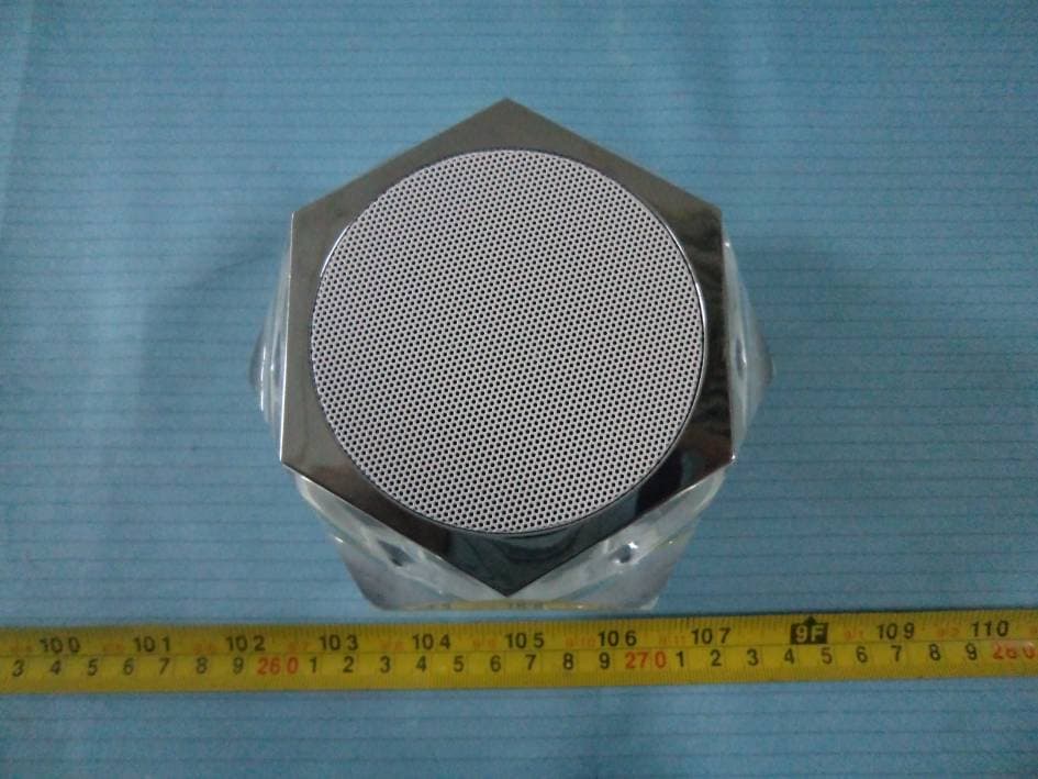
Click to zoom
Application Details
- Equipment Class
- DSS - Part 15 Spread Spectrum Transmitter
- Date of Grant
- Apr 08, 2014
- Application Purpose
- Original Equipment
- Date of Application
- Apr 08, 2014
- Equipment Note
- Crystal Bluetooth Speaker
- Frequency Range
- 2402.00000000 - 2480.00000000
- Company
- Sound Crush Company Limited
- Country
- China
Documents & Files
Document Text
Text extracted from the exhibit documents filed with the FCC. Open a document above to read the original.
Users Manual
Crystal HR-890 Bluetooth Speaker What’s in the box? 1 x HR-890 Bluetooth speaker1 x Mini USB charge cable 1 x Users manual1 x AUX cable (Next) Volume up Volume down(previous) Hand-free Power LED light set USB port AUX-in Charging indicator Charging the HR-890 (3.7V rechargeable battery built-in) 1- Connect HR-890 with PC/Laptop/Mac or any 5V USB adaptor(not included) with the USB cable included 2- Charging indicator light blinks in Red during charging, turns OFF after fully charged. 3- Unplug USB cable after fully charged. Start the HR-890 1- After fully charged, hold the power button to turn on the speaker. 2- LED blinks in White and Red color alternatively. 3- HR-890 is in standby for pairing, with indication voice. AUTO power-off and re-start 1- HR-890 goes to standby status for power-saving purpose if no work for 3 minutes 2- Press any one button located on top to wake up HR-890 from standby. 3- To manually turn off the speaker, use the on/off power switch Paring HR-890with mobiles (Bluetooth enabled) and Tablets. 1- Please keep the speaker and mobile within 1 meter. 2- Turn on HR-890, white & red LED blinks quickly, the speaker is standby for pairing. 3- Start the Bluetooth function of mobile and search the Bluetooth devices, after searched, select “HR-890” in the Bluetooth device list. As per of the pairing process, you may need to enter a passkey (0000) depending on Bluetooth version of devices. 4- After successful pairing, select “HR-890” in the Bluetooth device list, and press “connect” 5- After successful connecting, LED changes to solid white. Note: 1: If the pairing is not successful, turn off speaker firstly, and then re-pair again. 2: After successful pairing, paired devices will remember each other. Unless pairing information is deleted, no need to pair when use next time. 3: If you want to pair the speaker with other devices, please disconnect with existing device firstly, and then pair with the new device according to steps 1-6 mentioned above. Paring HR-890 with iPhone, iPad 1- Please keep HR-890 and iPhone (iPad) in the range of 1 meter when pairing. 2- Turn on HR-890, LED blinks in Red and White color quickly, the unit is standby for pairing. 3- In iPhone (iPad) General > Bluetooth, tap on Bluetooth function, and search the Bluetooth devices, tap HR-890 to connect it. Paring HR-890 with PC or notebook 1- Please keep HR-890 and PC in the range of 1 meter when pairing. 2- Turn on HR-890, white & red LED blinks quickly, the unit is standby for pairing. 3- Run Bluetooth program of your system. 4- Please use “Search new device” function in the program. 5- Your system should find HR-890 on your dialog, then double click the icon to confirm the program should show the connection has been made. As per of the pairing process, you may need to enter a passkey (0000) depending on Bluetooth version of devices. Pairing HR-890 with Mac OS X 10 or above 1- Please keep HR-890 and Mac in the range of 1 meter when pairing. 2- Turn on HR-890, white & red LED blinks quickly, the unit is standby for pairing. 3- Pair it with Mac – choose setup Bluetooth Device from the Bluetooth status menu in the menu bar, and follow the onscreen instructions to pair with the speaker. If the Bluetooth status menu is not available, open Bluetooth Preference and select the “Show Bluetooth status in the menu bar” checkbox. As per of the pairing process, you may need to enter a passkey (0000) depending on Bluetooth version of devices. 4- Open System Preferences and click Sound. 5- Click Output and select the Bluetooth speaker. 6- Click Input and select your speaker. Adjust the Input and Output volume. Note: Some applications, including iChat AV, allow you to select the audio device from within the application (independently of the default audio input and output selected on the Sound pane of System Preferences). To use a Bluetooth speaker with iChat AV, select the Bluetooth speaker for audio input and output on the Video pane of iChat preferences. Re-connecting to a paired device Every time HR-890 is turned on, it has one of 2 conditions as below 1- Connect to last connected devices automatically, then just start music playback. 2- Belisted in the screen of devices as a output channel, then please select HR-890 as output channel and play music. Hand- free when have a coming call 1- Short press “Hand-free”to answer phone call. 2- Short press again to end a call. LED light set 1- The LED light will show below colors when HR-890 is turned on A: Red and White blinks – standby for pairing. B: Solid White – successfully paired C: Solid Green light – in AUX mode D: OFF – LED is turn off manually 2- Press “LED light set” button, LED will blink in different colors according to Music rhythm. 3- Press again, LED will go to “breathing” mode to change colors (white, purple, red) slowly. 4- When HR-890 is turn off, hold “LED light set” button to turn on the light only, press again to change color, hold again to turn off the light. Volume control 1- Control volume via the Bluetooth device itself. 2- Control volume via the volume +/- buttons located on top of HR-890. AUX port 1- You can connect AUX port to any music devices via the AUX cable included. 2- Then play music through the devices connected. FCC Caution: Any Changes or modifications not expressly approved by the party responsible for compliance could void the user's authority to operate the equipment. This device complies with part 15 of the FCC Rules. Operation is subject to the following two conditions: (1) This device may not cause harmful interference, and (2) this device must accept any interference received, including interference that may cause undesired operation. FCC Radiation Exposure Statement: This equipment complies with FCC radiation exposure limits set forth for an uncontrolled environment. This transmitter must not be co-located or operating in conjunction with any other antenna or transmitter. Note: This equipment has been tested and found to comply w…
Text truncated - open the document above for the full version.
External Photos
EXHIBIT B - EUT EXTERNAL PHOTOGRAPHS EUT – Front View EUT – Rear View EUT – Top View EUT – Bottom View EUT – Left Side View EUT – Right Side View EUT – AUX Cable View EUT– Mini USB Charge Cable View
ID Label/Location Info
EXHIBIT A - FCC ID LABEL AND LOCATION FCC ID Label FCC ID Label Location Information Specifications : Text is Black or white in color and is left justified. Labels are printed in indelible ink on permanent adhesive backing or silk-screened onto the EUT or shall be affixed at a conspicuous location on the EUT. Label here
Internal Photos
EXHIBIT C - EUT INTERNAL PHOTOGRAPHS EUT – Cover off View 1 EUT – Cover off View 2 EUT – Cover off View 3 EUT – Main Board Top View EUT – Main Board Bottom View EUT – Sub Board Top View ANTENNA EUT – Sub Board Bottom View EUT – Battery View
Test Report
Note: This test report is prepared for the customer shown above and for the equipment described herein. It may not be duplicated or used in part without prior written consent from Bay Area Compliance Laboratories Corp. FCC PART 15.247 TEST REPORT For Sound Crush Company Limited Bldg 8, Xiang YuEr Ind.Park, LongSheng Road, Long Gang, ShenZhen, China FCC ID: 2ABPR110210MCOMBO Report Type: Original Report Product Type: Crystal Bluetooth Speaker Test En gineer: Simon Wang Re port Number: RSZ140109002-00 Re port Date: 2014-01-17 Reviewed B y: Sula Huang RF En gineer Prepared By: Bay Area Compliance Laboratories Corp. (Shenzhen) 6/F, the 3rd Phase of WanLi Industrial Building ShiHua Road, FuTian Free Trade Zone Shenzhen, Guangdong, China Tel: +86-755-33320018 Fax: +86-755-33320008 www.baclcorp.com.cn Bay Area Compliance Laboratories Corp. (Shenzhen) Report No.: RSZ140109002-00 FCC Part 15.247 Page 2 of 64 TABLE OF CONTENTS GENERAL INFORMATION ....................................................................................................................................... 4 PRODUCT DESCRIPTION FOR EQUIPMENT UNDER TEST (EUT) ..................................................................................... 4 OBJECTIVE ................................................................................................................................................................... 4 RELATED SUBMITTAL(S)/GRANT(S) ............................................................................................................................. 4 TEST METHODOLOGY .................................................................................................................................................. 4 TEST FACILITY ............................................................................................................................................................. 5 SYSTEM TEST CONFIGURATION .......................................................................................................................... 6 DESCRIPTION OF TEST CONFIGURATION ...................................................................................................................... 6 EUT EXERCISE SOFTWARE .......................................................................................................................................... 6 SPECIAL ACCESSORIES ................................................................................................................................................. 6 EQUIPMENT MODIFICATIONS ....................................................................................................................................... 6 SUPPORT EQUIPMENT LIST AND DETAILS .................................................................................................................... 6 EXTERNAL I/O CABLE .................................................................................................................................................. 6 BLOCK DIAGRAM OF TEST SETUP ................................................................................................................................ 7 SUMMARY OF TEST RESULTS ............................................................................................................................... 8 FCC §15.247 (i) & §2.1093 – RF EXPOSURE ............................................................................................................ 9 APPLICABLE STANDARD .............................................................................................................................................. 9 FCC §15.203 – ANTENNA REQUIREMENT .......................................................................................................... 10 APPLICABLE STANDARD ............................................................................................................................................ 10 ANTENNA CONNECTOR CONSTRUCTION .................................................................................................................... 10 FCC §15.207 (a) – AC LINE CONDUCTED EMISSIONS ..................................................................................... 11 APPLICABLE STANDARD ............................................................................................................................................ 11 MEASUREMENT UNCERTAINTY .................................................................................................................................. 11 EUT SETUP ................................................................................................................................................................ 11 EMI TEST RECEIVER SETUP ....................................................................................................................................... 12 TEST PROCEDURE ...................................................................................................................................................... 12 TEST EQUIPMENT LIST AND DETAILS ......................................................................................................................... 12 CORRECTED FACTOR & MARGIN CALCULATION ....................................................................................................... 12 TEST RESULTS SUMMARY .......................................................................................................................................... 13 TEST DATA ................................................................................................................................................................ 13 FCC §15.205, §15.209 & §15.247(d) – RADIATED EMISSIONS ........................................................................... 16 APPLICABLE STANDARD .....................................................................................................................................…
Text truncated - open the document above for the full version.
Test Setup Photos
EXHIBIT D - TEST SETUP PHOTOGRAPHS Conducted Emissions - Front View Conducted Emissions - Side View Radiated Emissions – Front View (Below 1 GHz) Radiated Emissions – Rear View (Below 1 GHz) Radiated Emissions – Front View (Above 1 GHz) Radiated Emissions – Rear View (Above 1 GHz)
Contact Information
Applicant
Baker Zhang
Test Firm
Bay Area Compliance Laboratory Corp. (Shenzhen)John Chan
Technical Specifications
| # | Rule Parts | Frequency Range | Power Output |
|---|---|---|---|
| 1 | 15C | 2.40 GHz - 2.48 GHz | 3.20 mW |
Other Applications from Sound Crush Company Limited
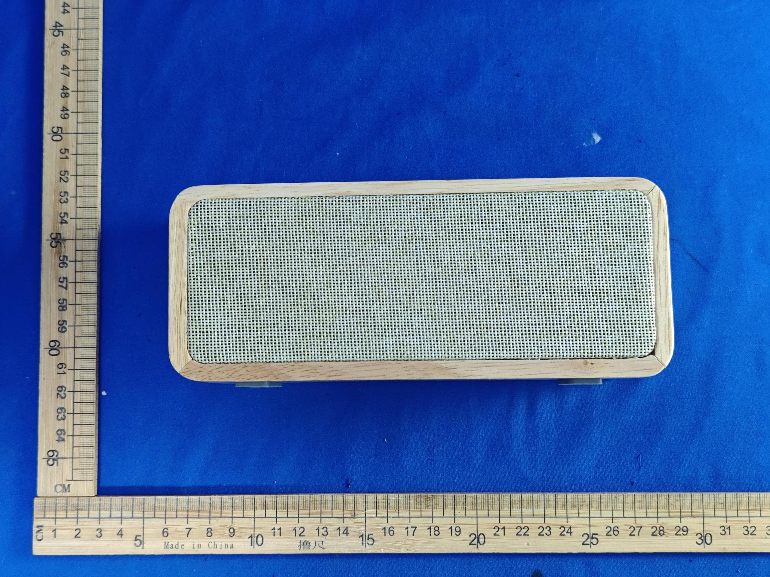
2ABPR-FS-10
Jul 12, 2024Bluetooth TWS Speaker
Equipment Class
DSS - Part 15 Spread Spectrum Transmitter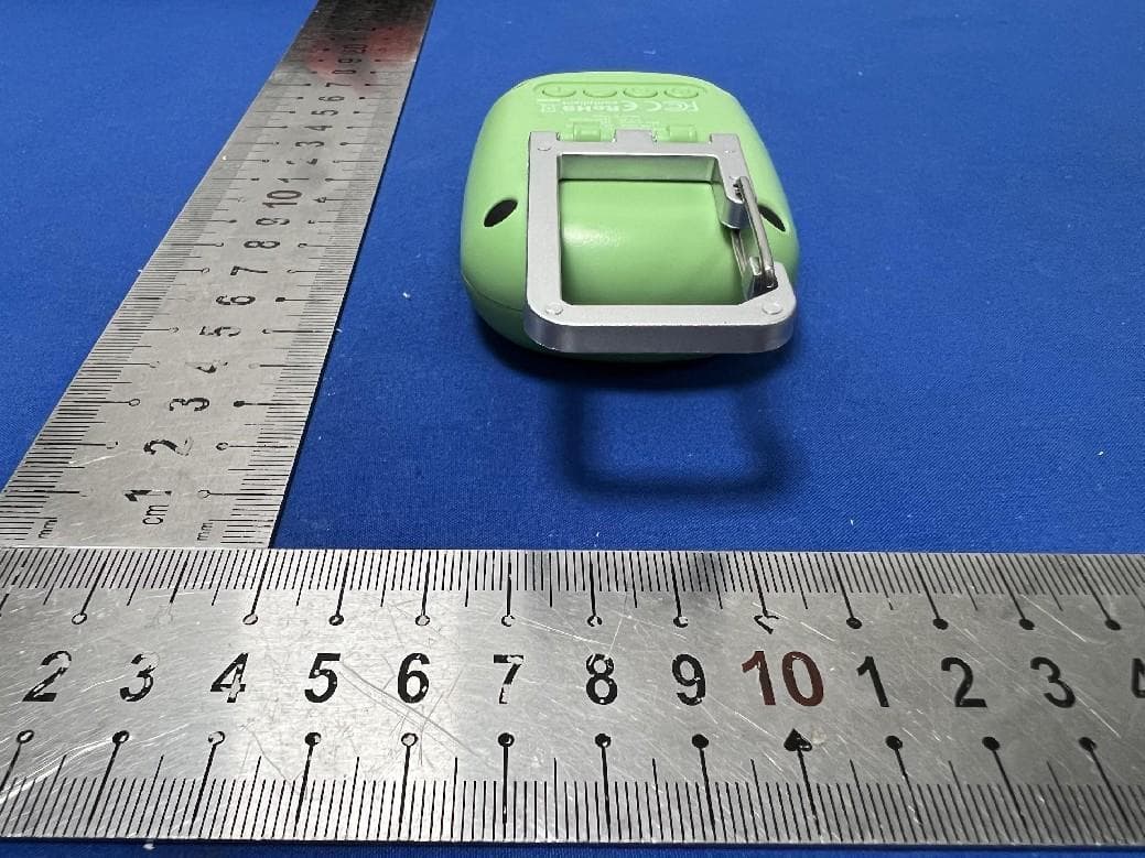
2ABPRSC909
Jul 09, 2023Sound Machine
Equipment Class
DSS - Part 15 Spread Spectrum Transmitter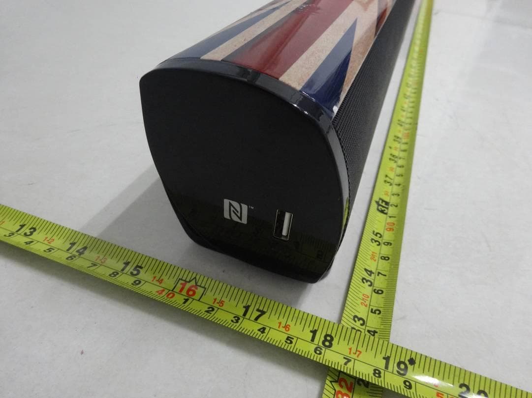
2ABPRHR-917
May 06, 2015SoundBar
Equipment Class
DSS - Part 15 Spread Spectrum Transmitter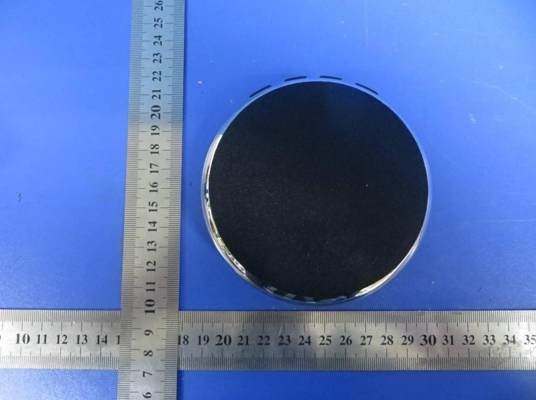
2ABPRHR-918
Dec 18, 2014Air Speaker (Bluetooth Speaker)
Equipment Class
DSS - Part 15 Spread Spectrum Transmitter