2ABU6-MS47SF1Bluetooth 4.0 Module
Shenzhen Minew Technologies Co., Ltd.
Click to zoom
Application Details
- Equipment Class
- DXX - Part 15 Low Power Communication Device Transmitter
- Date of Grant
- Mar 25, 2014
- Application Purpose
- Original Equipment
- Date of Application
- Mar 25, 2014
- Equipment Note
- Bluetooth 4.0 Module
- Frequency Range
- 2402.00000000 - 2480.00000000
- Country
- China
Documents & Files
Document Text
Text extracted from the exhibit documents filed with the FCC. Open a document above to read the original.
Users Manual
TEL: +86-755-8886 8480 FAX: +86-755-2982 5342 EMAIL: [email protected] URL: www.rfodm.com Page 1 Minew Technologies Bluetooth 4.0 Module Instructions V1.0 Description This module is limited to OEM Installation only. The MS47SF1 smart module is a SMD package module basis of CC2541 chip, it is a smart module with cost-effe ctive, low power, true system-on-chip (SoC) for Bluetooth low energy applications. It enables robust BLE master or salve nodes to be built with very low total bill of material costs. The MS47SF1 smart module combines an excellent RF transceiver with an industry-standard enhanced 8051 MCU, in-system programmable 256KB flash memory, 8KB RAM, and many powerful supporting features and peripherals. It is s uitable for systems where very low power consumption is required. Very low-power sleep modes are available. Short transmission times between operating modes further enable low power consumption. Features - Bluetooth low energy technology compatible - Excellent link budget (up to 97dB) - Enable long range applications - Accurate digital RSSI - Compatible with CE and FCC regulation - High performance and low power 8051 core MCU - Battery monitor and temperature sensor - Samples application and profiles - Full speed USB interface - AES security coprocessor Application - 2.4GHz Bluetooth low energy systems - Mobile phone accessories - Sports and leisure equipment - Consumer electronics - Human interface devices (keyboard, mouse, remote control and etc.) - USB dongles - Healthcare and medical Images Top view Bottom view TEL: +86-755-8886 8480 FAX: +86-755-2982 5342 EMAIL: [email protected] URL: www.rfodm.com Page 2 Minew Technologies Bluetooth 4.0 Module Instructions V1.0 Mechanical Footprint (Unit: mm) Pin Description Pin Symbol Pin Type Definition ANT Null External antenna GND Ground The ground pin should be connected to the cathode of power supply 3.3V Power The 3.3V pin should be connected to the positive of power supply P2.2 Digital I/O Port 2.2 P2.1 Digital I/O Port 2.1 P2.0 Digital I/O Port 2.0 P1.7 Digital I/O Port 1.7 P1.6 Digital I/O Port 1.6 DP Digital I/O USB P DM Digital I/O USB N P1.5 Digital I/O Port 1.5 P1.4 Digital I/O Port 1.4 P1.3 Digital I/O Port 1.3 RESET-N Digital I/O Reset, active low P0.0 – P0.7 Digital I/O Port 0.0 – Port 0.7 P1.0 Digital I/O Port 1.0 – 20mA drive capability P1.1 Digital I/O Port 1.1 – 20mA drive capability TEL: +86-755-8886 8480 FAX: +86-755-2982 5342 EMAIL: [email protected] URL: www.rfodm.com Page 3 Minew Technologies Bluetooth 4.0 Module Instructions V1.0 Electronic Parameters Item Test Data Remarks Operation Voltage 2.0-3.6V DC Operation Frequency 2400-2483.5MHz Programmable Frequency Error +/- 20KHz Null Modulation Q-QPSK Null Output Power 0 dBm Programmable Receiving Sensitivity -93dBm High gain mode Receiving Current 17.9mA High gain mode Transmission Current 18.2mA Transmission power 0dBm Sleep consumption 0.uA Power mode 3, connection-less state Transmission distance 50 meters BER<0.1%, Open space Antenna 50ohm Null Dimension 12*16*1.7mm Null Debugger / UART Interface MS47SF1 smart module TI JTAG Definition Host Information This module was defined to be used for specific host only. The designated host for this module was: Model: MS51PX1 Brand Name: MINEW Manufacturer: Shenzhen Minew Technologies Co.,Ltd. Address: 5 Floor, H Building, Gangzhilong Science Park, Qinglong Road, Longhua District, Shenzhen City, China FCC RF Exposure Requirement 1. At least 20cm separation distance between the antenna and the user’s body must be maintained at all times. And must not transmit simultaneously with any other antenna or transmitter, except in accordance with FCC multi transmitter product procedures. 2. To comply with FCC regulations limiting both maximum RF output power and human exposure to RF radiation, the maximum antenna gain including cable loss in a mobile-only exposure condition must not exceed 0dBi in the 2.4G band. 3. A user manual with the end product must clearly indicate the operating requirements and conditions that must be observed to ensure compliance with current FCC RF exposure guidelines. Please be noticed following information and instructions should be placed in the end-user’s operating manual The Module has been granted as limited modular approval for mobile applications. This Module must be installed in the designated host as specified in this manual. 1. Separate approval is required for all other operating configurations, including portable configurations with respect to 2.1093 and different antenna configurations. 2. The Module and its antenna must not be co-located or operating in conjunction with any other transmitter or antenna within a host device. This equipment complies with FCC RF radiation exposure limits set forth for an uncontrolled environment. 3. A label must be affixed to the outside of the end product into which the module is incorporated, with a statement similar to the following: For MS47SF1: This device contains FCC ID: 2ABU6-MS47SF1. 4. The module shall be in non-detachable construction protection into the finished products, so that the end-user has to destroy the module while remove or install it. 5. This module is to be installed only in mobile or fixed applications. According to FCC part 2.1091(b) definition of mobile and fixed devices is:. Mobile device: A mobile device is defined as a transmitting device designed to be used in other than fixed locations and to generally be used in such a way that a separation distance of at least 20 centimeters is normally maintained between the transmitter’s radiating structure(s) and the body of the user or nearby persons. In this context, the term ‘‘fixed location’’ means that the device is physically secured at one location and is not able to be easily moved to another location. Portable device: For purposes of this section, a portable device is defined as a transmitting device designed to be used so that the radiating structure(s) of the device is/are within 2…
Text truncated - open the document above for the full version.
Cover Letter(s)
PART 15 UNLICENSED MODULAR TRANSMITTER APPROVAL COVER LETTER: Product Name: Bluetooth 4.0 Module Brand Name: MINEW Model Number: MS47SF1, MS47SF2, MS47SF3, MS47SF4, MS47SF5, MS47 series Applicant: Shenzhen Minew Technologies Co.,Ltd. 5 Floor, H Building, Gangzhilong Science Park, Qinglong Road, Longhua District, Shenzhen City, China Host Specification during testing: Model: MS51PX1 Brand Name: MINEW Manufacturer: Shenzhen Minew Technologies Co.,Ltd. Test Institution Shenzhen CTL Testing Technology Co., Ltd. We, Shenzhen CTL Testing Technology Co., Ltd., were authorized by Applicant to test Bluetooth Module in compliance with PART 15 UNLICENSED MODULAR TRANSMITTER APPROVAL 8 requirements of DA 00-1407stated as follow: 1. The modular transmitter must have its own RF shielding. This is intended to ensure that the module does not have to rely upon the shielding provided by the device into which it is installed in order for all modular transmitter emissions to comply with Part 15 limits. It is also intended to prevent coupling between the RF circuitry of the module and any wires or circuits in the device into which the module is installed. Such coupling may result in non-compliant operation. Please see the internal photo of EUT, the device no covered with shield, it is Limited Modular Approval. 2. The modular transmitter must have buffered modulation/data inputs (if such inputs are provided) to ensure that the module will comply with Part 15 requirements under conditions of excessive data rates or over-modulation. Please see the block diagram and schematic the applicant use GFSK(FHSS) buffered modulation/data inputs on integrated circuit for complying with Part 15 requirements 3. The modular transmitter must have its own power supply regulation. This is intended to ensure that the module will comply with Part 15 requirements regardless of the design of the power supplying circuitry in the device into which the module is installed. Please see the circuitry the applicant designed own power supply regulation with power supply integrated circuit in the device. 4. The modular transmitter must comply with the antenna requirements of Section 15.203 and 15.204(c). The antenna must either be permanently attached or employ a “unique” antenna coupler (at all connections between the module and the antenna, including the cable). Any antenna used with the module must be approved with the module, either at the time of initial authorization or through a Class II permissive change. The “professional installation” provision of Section 15.203 may not be applied to modules. Please see the internal photo of EUT. The antenna is printed on PCB and no consideration of replacement. 5. The modular transmitter must be tested in a host configuration. This is intended to demonstrate that the module is capable of complying with Part 15 emission limits regardless of the device into which it is eventually installed. Unless the transmitter module will be battery powered, it must comply with the AC line conducted requirements found in Section 15.207. AC or DC power lines and data input/output lines connected to the module must not contain ferrites, unless they will be marketed with the module (see Section 15.27(a)). The length of these lines shall be length typical of actual use or, if that length is unknown, at least 10 centimeters to insure that there is no coupling between the case of the module and supporting equipment. Any accessories, peripherals, or support equipment connected to the module during testing shall be unmodified or commercially available (see Section 15.31(i)). Please see the test setup and EUT photos. The applicant has supplied a host configuration to the module transmitter during the test. Please see the top of page 1 statement for the HOST. 6. The modular transmitter must be labeled with its own FCC ID number, and, if the FCC ID is not visible when the module is installed inside another device, then the outside of the device into which the module is installed must also display a label referring to the enclosed module. This exterior label can use wording such as the following: “Contains Transmitter Module FCC ID: XYZMODEL1” or “Contains FCC ID: XYZMODEL1.” Any similar wording that expresses the same meaning may be used. The Grantee may either provide such a label, an example of which must be included in the application for equipment authorization, or, must provide adequate instructions along with the module which explain this requirement. In the latter case, a copy of these instructions must be included in the application for equipment authorization. Please see the FCC Statement in user manual. 7. The modular transmitter must comply with any specific rule or operating requirements applicable to the transmitter and the manufacturer must provide adequate instructions along with the module to explain any such requirements. A copy of these instructions must be included in the application for equipment authorization. For example, there are very strict operational and timing requirements that must be met before a transmitter is authorized for operation under Section 15.247. Compliance with these requirements must be assured. Please see the User Manual for more details in which the user and the installer had installation step-by-step instructions on which to learn how to install and verify operation. 8. The modular transmitter must comply with any applicable RF exposure requirements. For example, FCC Rules in Sections 2.1091, 2.1093 and specific Sections of Part 15, including 15.319(i), 15.407(f), 15.253(f) and 15.255(g), require that Unlicensed PCS, UNII and millimeter wave devices perform routine environmental evaluation for RF Exposure to demonstrate compliance. In addition, spread spectrum transmitters operating under Section 15.247 are required to address RF Exposure compliance in accordance with Section 15.249. Modular transmitters approved under other Sections of Part 15, when necessary, may also need to…
Text truncated - open the document above for the full version.
Cover Letter(s)
Shenzhen Minew Technologies Co.,Ltd. 5 Floor, H Building, Gangzhilong Science Park, Qinglong Road, Longhua District, Shenzhen City, China Tel: +86-755-88868480 Fax: +86-755-29825342 AGENCY AUTHORIZATION LETTER FCC ID: 2ABU6-MS47SF1 Date: Mar. 18, 2014 Federal Communications Commission Authorization and Evaluation Division 7435 Oakland Mills Road Columbia, MD 21046 To whom it may concern: We, the undersigned, hereby authorize Shenzhen CTL Testing Technology Co., Ltd.(MR. Tracy Qi) on our behalf, to apply to the Federal Communications Commission on our equipment. Any and all acts carried out by Shenzhen CTL Testing Technology Co., Ltd. (MR. Tracy Qi) on our behalf shall have the same effect as acts of our own. This authorization expires on Mar. 17, 2015. This is to advise that we are in full compliance with the Anti-Drug Abuse Act. We, Shenzhen Minew Technologies Co.,Ltd. are not subject to a denial of federal benefits pursuant to Section 5301 of the Anti-Drug Act of 1988, 21 USC853a, and no party to the application is subject to a denial of federal benefits pursuant to that section. Sincerely, ------------------------------- Xiao Sheng/ Engineer
Cover Letter(s)
Shenzhen Minew Technologies Co.,Ltd. 5 Floor, H Building, Gangzhilong Science Park, Qinglong Road, Longhua District, Shenzhen City, China Tel: +86-755-88868480 Fax: +86-755-29825342 Series Models Description FCC ID: 2ABU6-MS47SF1 Date: Mar. 18, 2014 Federal Communications Commission Authorization and Evaluation Division 7435 Oakland Mills Road Columbia, MD 21046 To whom it may concern: To whom concern: The device (Product Name: Bluetooth 4.0 Module) Models Name: MS47SF1, MS47SF2, MS47SF3, MS47SF4, MS47SF5, MS47series, MS51PX1, MS52PX1, MS53PX1, MS54PX1, MS55PX1, MS56 Series have same electrical, PCB and BOM, only the model’s name is different for marketing requirements. Sincerely, ------------------------------- Xiao Sheng/ Engineer
External Photos
External Photos of EUT
ID Label/Location Info
FCC ID Label Information 1. Label location: 、 2. FCC ID Label: Shenzhen Minew Technologies Co.,Ltd. Wireless Controller Model: MS51PX1 Contain Tx Module FCC ID: 2ABU6-MS47SF1
Internal Photos
Internal Photos of EUT
Operational Description
Operation Description MS47SF1 module is a transceiver module which working at 2402-2480MHz frequency band. Externally provides DC3V power to make SOIC work; 32.768 KHz crystal oscillator provides the external clock signal to make the internal microcontroller work properly; 32 MHZ crystal oscillator provides the RF reference signal, to make the RF part working at 2.4G frequency band, and through the 2.4G antenna signal radiated; GPIO inputs and outputs to the microcontroller signal is processed by the microcontroller. When the module has been burned entry application, access to external power supply, module accordance with the program initializes the registers, then enter to the transceiver state.
Schematics
11 22 33 44 D D C C B B A A 2014/1/13F:\HardWare\MS47SFX\MS47SF1\MS47SF1_SCH_V11.SchDoc Title:Size: Number: Date:File: Revision:Sheet of Drawn By: MS47SF1 V1.1 1 1 1Shain A4 C6 1uF GND VCC VCC VCC R1 56K GND VCC 4 OUT 3 GND 2 IN 1 Y232MHz GND GND C13 12pF C1212pF GND GND VCCVCC VCC GND VCC C7 18pF C1018pF L12nH GND C111pF GND L4 2nH C8 1pF L2 1nH C91pF L3 3nH GND ANT SCLSDAP1.5P1.1P1.2P1.3P1.4 RESET_N P0.0 P0.1 P0.2 P0.3 P0.4 P0.5 P0.6 P0.7 P1.0 P1.6 P1.7 P2.0 P2.1 P2.2 Y132.768K C4 15pF C5 15pF GND GND C2 100nF C3 100nF C1 100nF VCC VCC VCC GND GND GND R2NC ANT1 C14 100nF VCC GND 987654321 101112131415161718 SDASCLP1.6P2.0P2.1P2.2VCCGNDANT1 RESET_N P0.0P0.1P0.2P0.3P0.4P0.5P0.6P0.7 GND 1 SCL 2 SDA 3 NC 4 P1.5 5 P1.4 6 P1.3 7 P1.2 8 P1.1 9 DVDD2 10 P1.0 11 P0.7 12 P0.6 13 P0.5 14 P0.4 15 P0.3 16 P0.2 17 P0.1 18 P0.0 19 RESET_N 20 AVDD5 21 XOSC1 22 XOSC2 23 AVDD3 24 RF_P 25 RF_N 26 AVDD2 27 AVDD1 28 AVDD4 29 R_BIAS 30 AVDD6 31 P2.4/XOSC32K1 32 P2.3/XOSC32K2 33 P2.2 34 P2.1 35 P2.0 36 P1.7 37 P1.6 38 DVDD1 39 DCOUPL 40 CC2541 U1 CC2541
Test Report
Shenzhen CTL Testing Technology Co., Ltd. Tel: +86-755-89486194 Fax: +86-755-26636041 FCC PART 15 SUBPART C TEST REPORT FCC Part 15.249 Report Reference No......................: CTL1401200115-WF Compiled by ( position+printed name+signature)..: File administrators Jacky Chen Name of the organization performing the tests ( position+printed name+signature)..: Test Engineer Tracy Qi Approved by ( position+printed name+signature)..: Manager Tracy Qi Date of issue.....................................: Feb.18, 2014 Test Firm..........................................: Shenzhen CTL Testing Technology Co., Ltd. Address.............................................: Floor 1-A, Baisha Technology Park, No. 3011, Shahexi Road, Nanshan, Shenzhen 518055 China. Applicant’s name............................: Shenzhen Minew Technologies Co., Ltd. Address.............................................: 5 Floor, H Building, Gangzhilong Science Park, Qinglong Road, Longhua District, Shenzhen City, China Test specification: Standard ...........................................: FCC Part 15.249: Operation within the bands 920-928 MHz, 2400- 2483.5 MHz, 5725-5850 MHz and 24.0 - 24.25 GHz. TRF Originator ..................................: Shenzhen CTL Testing Technology Co., Ltd. Master TRF.......................................: Dated 2011-01 Shenzhen CTL Testing Technology Co., Ltd. All rights reserved. This publication may be reproduced in whole or in part for non-commercial purposes as long as the Shenzhen CTL Testing Technology Co., Ltd. is acknowledged as copyright owner and source of the material. Shenzhen CTL Testing Technology Co., Ltd. takes no responsibility for and will not assume liability for damages resulting from the reader's interpretation of the reproduced material due to its placement and context. Test item description .................... : Bluetooth 4.0 module Trade Mark.......................................: MINEW Models/Type reference.....................: MS47SF1, MS47SF2, MS47SF3, MS47SF4, MS47SF5, MS47series, MS51PX1, MS52PX1, MS53PX1, MS54PX1, MS55PX1, MS56 Series Modulation .......................................: GFSK Work Frequency...........................: 2402 MHz~2480 MHz Antenna Type..............................: internal FCC ID .............................................: 2ABU6-MS47SF1 Result................................................: Positive V1.0 Page 2 of 27 Report No.: CTL1401200115-WF T E S T R E P O R T Test Report No. : CTL1401200115-WF Feb. 18, 2014 ______________________________________________________________________________________________ Date of issue Equipment under Test : Bluetooth 4.0 module Model /Type : MS47SF1 Listed Modes : MS47SF2, MS47SF3, MS47SF4, MS47SF5, MS47series, MS51PX1, MS52PX1, MS53PX1, MS54PX1, MS55PX1, MS56 Series Difference Description : Only the color and model's name is different. Applicant : Shenzhen Minew Technologies Co., Ltd. Address : 5 Floor, H Building, Gangzhilong Science Park, Qinglong Road, Longhua District, Shenzhen City, China Manufacturer Shenzhen Minew Technologies Co., Ltd. Address 5 Floor, H Building, Gangzhilong Science Park, Qinglong Road, Longhua District, Shenzhen City, China Test Result according to the standards on page 4: Positive The test report merely corresponds to the test sample. It is not permitted to copy extracts of these test result without the written permission of the test laboratory. V1.0 Page 3 of 27 Report No.: CTL1401200115-WF Contents 1. TEST STANDARDS .................................................................. 4 2. SUMMARY............................................................................. 5 2.1. General Remarks 5 2.2. Equipment Under Test 5 2.3. Short description of the Equipment under Test (EUT) 5 2.4. EUT operation mode 6 2.5. EUT configuration 6 2.6. Related Submittal(s) / Grant (s) 6 2.7. Modifications 6 3. TEST ENVIRONMENT............................................................... 7 3.1. Address of the test laboratory 7 3.2. Test Facility 7 3.3. Environmental conditions 7 3.4. Configuration of Tested System 7 3.5. Statement of the measurement uncertainty 8 3.6. Equipments Used during the Test 9 4. TEST CONDITIONS AND RESULTS ............................................ 10 4.1. Conducted Emissions Test 10 4.2. Radiated Emission Test 12 4.3. Band Edge Measurement 17 5. ANTENNA REQUIREMENT ....................................................... 21 6. TEST SETUP PHOTOS OF EUT ................................................. 22 7. EXTERNAL AND INTERNAL PHOTOS OF EUT.............................. 23 V1.0 Page 4 of 27 Report No.: CTL1401200115-WF 1. TEST STANDARDS The tests were performed according to following standards: FCC Rules Part 15.249: Operation within the bands 902 - 928 MHz, 2400 - 2483.5 MHz, 5725 - 5875 MHz, and 24.0 - 24.25 GHz. ANSI C63.4-2003 V1.0 Page 5 of 27 Report No.: CTL1401200115-WF 2. SUMMARY 2.1. General Remarks Date of receipt of test sample : Feb. 10, 2014 Testing commenced on : Feb. 10, 2014 Testing concluded on : Feb. 18, 2014 2.2. Equipment Under Test Power supply system utilised Power supply voltage : o 120V / 60 Hz o 115V / 60Hz o 12 V DC o 24 V DC ● Other (specified in blank below) DC 3.0V from battery(CR2477T) 2.3. Short description of the Equipment under Test (EUT) The EUT is a Bluetooth 4.0 modules work at 2402~2480 MHz. Channel List: Channel Frequency (MHz) Channel Frequency (MHz) 00 2402 20 2442 01 2404 21 2444 02 2406 22 2446 03 2408 23 2448 04 2410 24 2450 05 2412 25 2452 06 2414 26 2454 07 2416 27 2456 08 2418 28 2458 09 2420 29 2460 10 2422 30 2462 11 2424 31 2464 12 2426 32 2466 13 2428 33 2468 14 2430 34 2470 15 2432 35 2472 16 2434 36 2474 17 2436 37 2476 18 2438 38 2478 19 2440 39 2480 Power Range: -5dBm~0dBm Modulation: GFSK For more details, refer to the user’s manual of the EUT. Serial number: Prototype V1.0 Page 6 of 27 Report No.: CTL1401200115-WF 2.4. EUT operation mode Test Mode(TM) Description Remark TM1 Bottom Channel Tra…
Text truncated - open the document above for the full version.
Test Setup Photos
Test Setup Photos of the EUT
Contact Information
Applicant
yanyan Zhang(Quality Supervisor)
Test Firm
Shenzhen CTL Testing Technology Co., Ltd.Tracy Qi
[email protected]86-755-89486194
Technical Specifications
| # | Rule Parts | Frequency Range | Power Output |
|---|---|---|---|
| 1 | 15C | 2.40 GHz - 2.48 GHz | - |
Other Applications from Shenzhen Minew Technologies Co., Ltd.
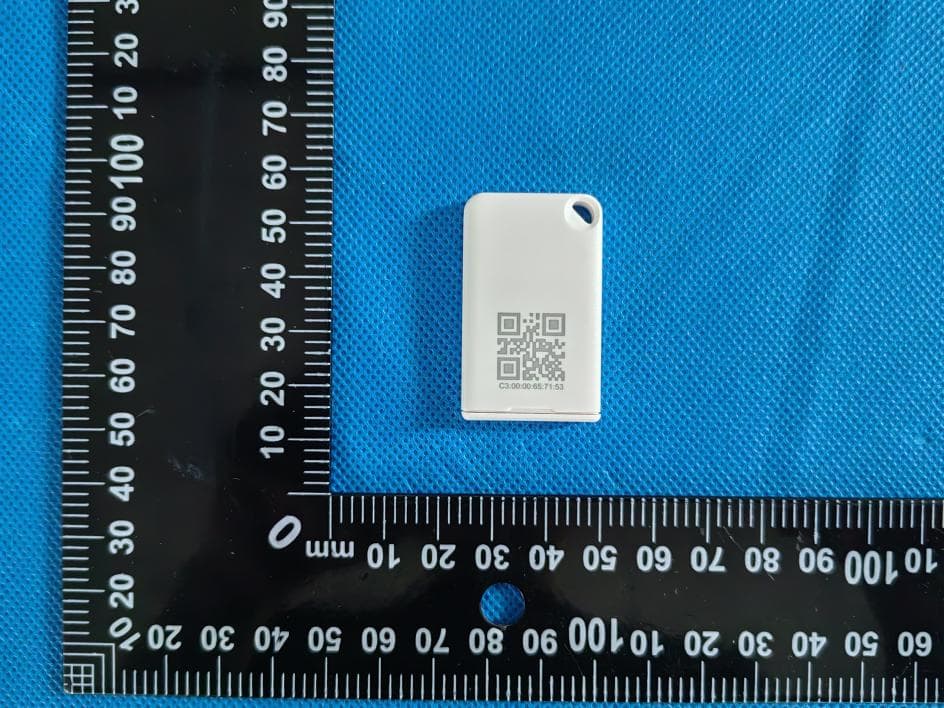
2ABU6-MTB12
May 20, 2026Waterproof Replaceable Battery Tag
Equipment Class
DTS - Digital Transmission System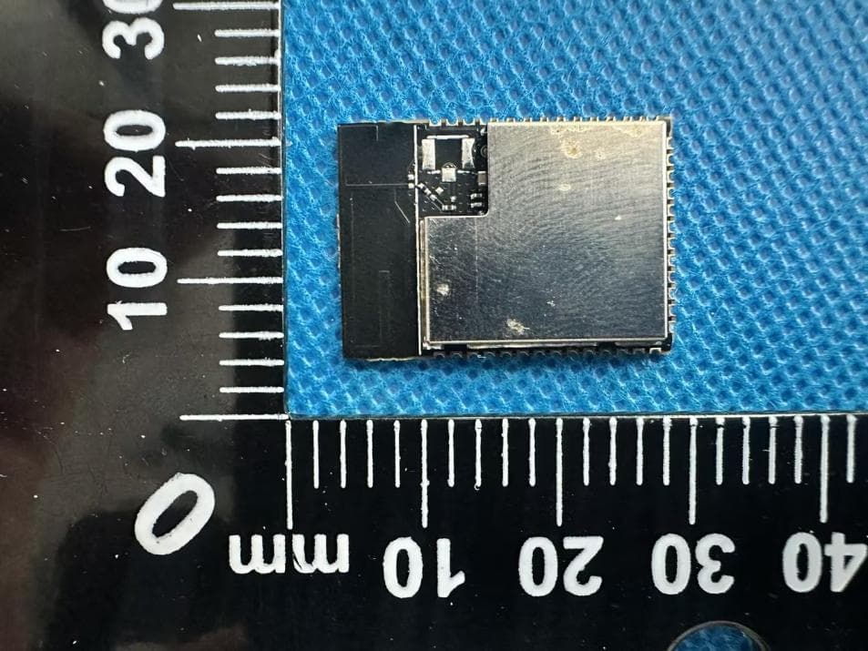
2ABU6-MD16WS01
Jan 30, 2026WiFi Module
Equipment Class
NII - Unlicensed National Information Infrastructure TX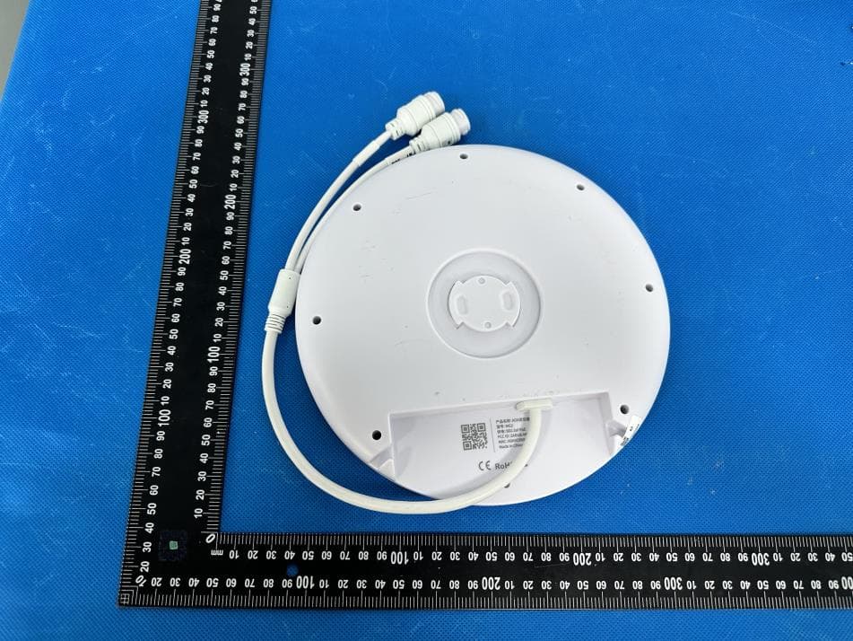
2ABU6-MG2
Jun 24, 2024AOA Positioning Base Station
Equipment Class
DTS - Digital Transmission System2ABU6-MST03
Jan 18, 2024Asset Temperature Logger
Equipment Class
DTS - Digital Transmission System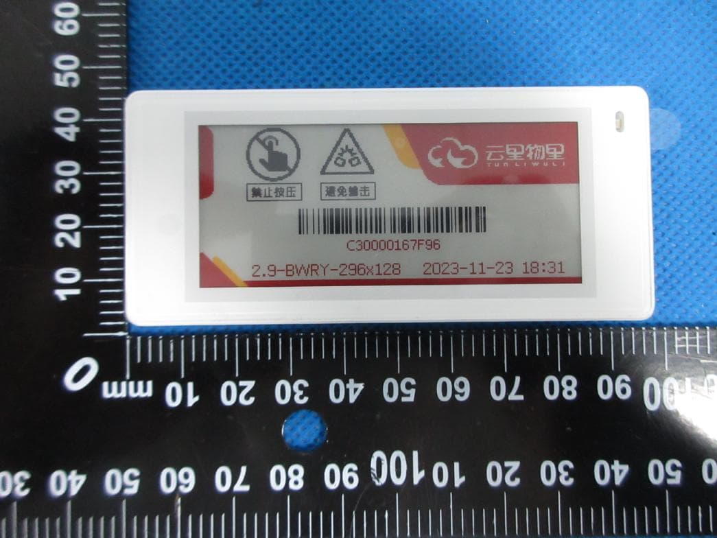
2ABU6-DS029
Dec 19, 2023Electronic Shelf Label
Equipment Class
DTS - Digital Transmission System