2ABUUDTE4027RFID Reader Module
BIO-RAD LABORATORIES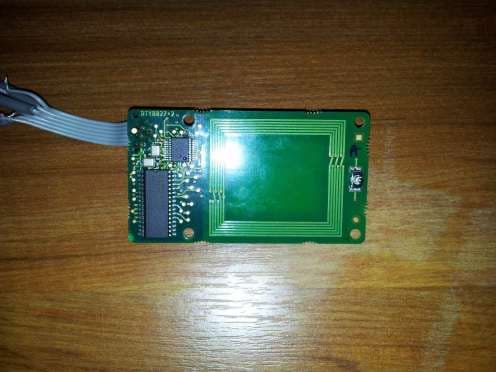
Click to zoom
Application Details
- Equipment Class
- DXX - Part 15 Low Power Communication Device Transmitter
- Date of Grant
- May 19, 2014
- Application Purpose
- Original Equipment
- Date of Application
- May 19, 2014
- Equipment Note
- RFID Reader Module
- Frequency Range
- 13.56000000 - 13.56000000
- Company
- BIO-RAD LABORATORIES
- Country
- France
Documents & Files
Document Text
Text extracted from the exhibit documents filed with the FCC. Open a document above to read the original.
Users Manual
User Manual DTE4027 RFID Reader Module REF DTE4027 February 2014 DTE4027 RFID Reader Module User Manual 1 Table of Contents 1 INTRODUCTION .............................................................................................................................. 6 1.1 General Description ................................................................................................................... 6 2 SPECIFICATIONS ............................................................................................................................ 6 2.1 Physical Specifications ............................................................................................................... 6 2.1.1 Dimensions ......................................................................................................................... 6 2.1.2 Weight ................................................................................................................................ 6 2.2 Technical Specifications ............................................................................................................. 6 2.2.1 General Specifications......................................................................................................... 6 3 SYSTEM DESCRIPTION .................................................................................................................. 7 3.1 Electrical Interface ..................................................................................................................... 7 3.2 Block Diagram ........................................................................................................................... 7 3.3 Mechanical Drawing ................................................................................................................... 8 4 INSTALLATION PROCEDURE ......................................................................................................... 9 4.1 Installation Requirements ........................................................................................................... 9 4.2 Installation ................................................................................................................................. 9 4.3 Command set ............................................................................................................................ 9 5 TROUBLESHOOTING ...................................................................................................................... 9 5.1 Error Messages.......................................................................................................................... 9 DTE4027 RFID Reader Module User Manual 2 Bio-Rad Laboratories 7, rue de Madrid 67300 Schiltigheim France CAUTION Please read through and familiarize yourself with the contents of the user manual. ABOUT THIS MANUAL: This manual is intended for design engineers and technicians. The following topics are included: • Principles of Operation • Technical Specifications • Module in system integration • Troubleshooting Guide Also included are electrical and mechanical drawings. DTE4027 RFID Reader Module User Manual 3 WARNING TO USERS IN THE UNITED STATES Federal Communication Commission Interference Statement 47 CFR Section 15.105(b) This equipment has been tested and found to comply with the limits for a Class B digital device, pursuant to Part 15 of the FCC Rules. These limits are designed to provide reasonable protection against harmful interference in a residential installation. This equipment generates uses and can radiate radio frequency energy and, if not installed and used in accordance with the instructions, may cause harmful interference to radio communications. However, there is no guarantee that interference will not occur in a particular installation. If this equipment does cause harmful interference to radio or television reception, which can be determined by turning the equipment off and on, the user is encouraged to try to correct the interference by one of the following measures: • Reorient or relocate the receiving antenna. • Increase the separation between the equipment and receiver. • Connect the equipment into an outlet on a circuit different from that to which the receiver is connected. • Consult the dealer or an experienced radio/TV technician for help. This device DTE4027 complies with Part 15 of the FCC Rules. Operation is subject to the following two conditions: (1) This device may not cause harmful interference, and (2) this device must accept any interference received, including interference that may cause undesired operation. NO UNAUTHORIZED MODIFICATIONS 47 CFR Section 15.21 CAUTION: This equipment may not be modified, altered, or changed in any way without signed written permission from BIO-RAD. Unauthorized modification may void the equipment authorization from the FCC and will void the BIO-RAD warranty. This device complies with FCC RF radiation exposure limits set forth for general population (uncontrolled exposure). This device must be installed to provide a separation distance of at least 20cm from all persons and must not be collocated or operating in conjunction with any other antenna or transmitter. DTE4027 RFID Reader Module User Manual 4 WARNING TO USERS IN THE CANADA / ATTENTION POUR LES UTILISATEURS AU CANADA This device complies with Industry Canada licence-exempt RSS standard(s). Operation is subject to the following two conditions: (1) this device may not cause interference, and (2) this device must accept any interference, including interference that may cause undesired operation of the device. Under Industry Canada regulations, this radio transmitter may only operate using an antenna of a type and maximum (or lesser) gain approved for the transmitter by Industry Canada. To reduce potential radio interference to other users, the antenna type and its gain should be so chosen that the equivalent isotropically radiated power (e.i.r…
Text truncated - open the document above for the full version.
External Photos
External views FCC Id: 2ABUUDTE4027
ID Label/Location Info
CARTE RFID DTE4027 EXTERNAL PHOTOS AND LABEL LOCATION
ID Label/Location Info
ETIQUETTE DTX8045 ECHELLE 1:1 ETIQUETTE DTX8045 ECHELLE 2:1
Internal Photos
Internal views FCC Id: 2ABUUDTE4027
Test Report
TEST REPORT N°125244-651735B Page 2/24 SUMMARY 1. TEST PROGRAM ............................................................................................................................... 3 2. EQUIPMENT DESCRIPTION .............................................................................................................. 4 3. OCCUPIED BANDWIDTH ................................................................................................................... 6 4. FREQUENCY TOLERANCE ............................................................................................................... 8 5. AC POWER LINE CONDUCTED EMISSIONS ................................................................................. 10 6. FIELD STRENGTH WITHIN THE BAND 13.110-14.010MHZ ............................................................ 13 7. FIELD STRENGTH OUTSIDE OF THE BANDS 13.110-14.010 MHZ ............................................... 15 8. TEST EQUIPMENT LIST .................................................................................................................. 19 9. UNCERTAINTIES CHART ................................................................................................................ 20 10. ANNEX (GRAPHS) .......................................................................................................................... 21 TEST REPORT N°125244-651735B Page 3/24 1. TEST PROGRAM References Standards: - 47 CFR Part 15C - RSS-210 - RSS-Gen - CISPR 16-4-2 - ANSI C63.4 Standard Section Test Description TEST RESULT - Comments RSS-Gen § 4.6.1 Occupied Bandwidth PASS (No Limit applicable) CFR 47 § 15.225 (e) RSS-210 § A2.6 Frequency tolerance PASS CFR 47 § 15.207 RSS-210 § 2.5.1 AC Power Line Conducted Emissions PASS CFR 47 § 15.225 (a) (b) (c) RSS-210 § A2.6 (a) (b) (c) Field strength within the band 13.110-14.010 MHz PASS CFR 47 § 15.209 (a) CFR 47 § 15.225 (d) RSS-210 § 2.5.1 Field strength outside of the bands 13.110-14.010 MHz PASS RSS-Gen § 4.10 Receiver Radiated emissions NA (Transceiver equipment. Include in Field strength test) PASS: EUT complies with standard’s requirement FAIL: EUT does not comply with standard’s requirement NA: Not Applicable NP: Test Not Performed TEST REPORT N°125244-651735B Page 4/24 2. EQUIPMENT DESCRIPTION 2.1. HARDWARE & SOFTWARE IDENTIFICATION Equipment under test (EUT): Front face Rear face Photograph of EUT Auxiliary equipment (AE) used for testing: Bulk Fluidics Master Board Contactless Card Photograph of AE Software identification: -Software version: PIC-MIFARE-CCL-170813, Version 1.10 Input/output: -Input Power TEST REPORT N°125244-651735B Page 5/24 Equipment information: - External antenna connector: No - Frequency band allocated: 13.553MHz to 13.567MHz - Frequency band used: 13.56MHz - Modulation: ASK 100% - Number of channel: 1 - Antenna type: Integral - Stand By mode: No - Maximum Antenna Gain: No available information - Type of power source: External power supply - Power supply: Vmin: 4.5V Vnom: 5 V Vmax: 5.5 V - Temperature range: Tmin: -30°C (IC) -20°C (FCC) Tnom: 20°C Tmax: +50°C 2.2. RUNNING MODE The EUT is set in the following modes during tests: -Communication with a tag 2.3. EQUIPEMENT LABELLING 2.4. EQUIPMENT MODIFICATIONS - Adding a ferrite reference 7427114 on power wires (5V) of flat cable (J1 connector) - Adding a ferrite reference 7427114 on data wires (5V) of flat cable (J1 connector) TEST REPORT N°125244-651735B Page 6/24 3. OCCUPIED BANDWIDTH 3.1. TEST CONDITIONS Test performed by : Armand MAHOUNGOU Date of test : 2014/01/08 Ambient temperature : 23°C Relative humidity : 36% 3.2. TEST SETUP The Equipment Under Test is installed on a table and set in permanent emission with modulation. Measurement is performed with a spectrum analyzer on the EUT with a test fixture. The product has been tested according to the RSS- GEN § 4.6.1 reference method. Spectrum Analyzer Setting: Center frequency= 13.56MHz Span= 3MHz Amplitude= Sufficient to observe the signal amplitude RBW= 1% of span VBW= 3*RBW Sweep= Auto Trace= Max Hold Detector= Peak Occupied Bandwidth 99% activated Photograph for Occupied Bandwidth TEST REPORT N°125244-651735B Page 7/24 Photograph for Occupied Bandwidth 3.3. RESULTS Temperature Tnom Voltage Vnom Frequency 13.56 Occupied Bandwidth (kHz) 1418.447 See graphics in annex Result: PASS Limit: None TEST REPORT N°125244-651735B Page 8/24 4. FREQUENCY TOLERANCE 4.1. TEST CONDITIONS Test performed by : Armand MAHOUNGOU Date of test : 2014/01/08 Ambient temperature : 23°C Relative humidity : 36% 4.2. TEST SETUP The Equipment Under Test is installed on a table and set in permanent emission with modulation. Measurement is performed with a spectrum analyzer on the EUT a test fixture. Spectrum Analyzer Setting: Center frequency= 13.56MHz Span= 300kHz Amplitude= Sufficient to observe the signal amplitude RBW= 3kHz VBW= 10kHz Sweep= Auto Trace= Max Hold Detector= Peak Photograph for Frequency tolerance TEST REPORT N°125244-651735B Page 9/24 Photograph for Frequency tolerance 4.3. RESULTS Temperature Tmin (IC) Tmin (FCC) Tnom Tmax Voltage: Vmin Frequency (MHz) 13,56 13,56015 13,56012 13,56015 Frequency Drift (%) -0,0009 0,0002 0,0000 0,0002 Voltage: Vnom Frequency (MHz) 13,56015 13,56015 13,56012 13,56018 Frequency Drift (%) 0,0002 0,0002 Reference 0,0004 Voltage: Vmax Frequency (MHz) 13,56015 13,5603 13,56024 13,5603 Frequency Drift (%) 0,0002 0,0013 0,0009 0,0013 Result: PASS Limit: +/- 0.01% TEST REPORT N°125244-651735B Page 10/24 5. AC POWER LINE CONDUCTED EMISSIONS 5.1. TEST CONDITIONS Test performed by : Laurent Deneux Date of test : 2014/01/06 Ambient temperature : 22°C Relative humidity : 47% 5.2. TEST SETUP The product has been tested according to ANSI C63.4-(2003) method. The EUT is placed on the ground reference plane, at 80cm from the LISN. The distance between the EUT and the vertical ground plane is 40cm. Auxiliaries are powered by another LISN. The cable has been shorted to 1meter l…
Text truncated - open the document above for the full version.
Test Setup Photos
Test setup photos FCC Id: 2ABUUDTE4027 IC: 11658A-DTE4027 Test setup for power line conducted emissions Test setup for power line conducted emissions Test setup for radiated field strength Test setup for radiated field strength Test setup for radiated field strength Test setup for radio conducted tests
Contact Information
Applicant
JEAN-MICHEL HENRY(QA MANAGER)
Test Firm
LCIEPatrick Pereira Teixeira
Technical Specifications
| # | Rule Parts | Frequency Range | Power Output |
|---|---|---|---|
| 1 | 15C | 13.56 MHz - 13.56 MHz | - |