2ABUYBHA-WN400Binary CDMA Compliant
EMW Co.,Ltd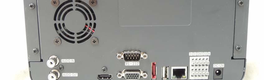
Click to zoom
Application Details
- Equipment Class
- DTS - Digital Transmission System
- Date of Grant
- Apr 30, 2014
- Application Purpose
- Original Equipment
- Date of Application
- Apr 30, 2014
- Equipment Note
- Binary CDMA Compliant
- Frequency Range
- 5735.00000000 - 5815.00000000
- Company
- EMW Co.,Ltd
- Country
- South Korea
Documents & Files
Document Text
Text extracted from the exhibit documents filed with the FCC. Open a document above to read the original.
Users Manual
0 ARNIX Wired/Wireless All-In-One Surveillance System User Manual Thank you for purchasing our wired/wireless all-in-one surveillance system. Before start using this product, please ensure that you read and understand the User Manual. Please store the User Manual at an easily accessible location. Before connecting and installing monitors, alarms and computers, please refer to the appropriate instruction manual for proper operation. 1 SAFETY PRECAUTIONS CAUTION: TO REDUCE THE RISK OF ELECTRIC SHOCK, DO NOT REMOVE COVER (OR BACK). NO USER SERVICEABLE PARTS INSIDE. REFER SERVICING TO QUALIFIED SERVICE PERSONNEL. The lightning flash with arrowhead symbol, within an equilateral triangle, is intended to alert the user to the presence of un insulated “dangerous voltage” within the product’s enclosure that may be of sufficient magnitude to constitute a risk of electric shock to persons. The exclamation point within an equilateral triangle is intended t o alert the user to the presence of important operating and mai ntenance (servicing) instructions in the literature accompanying t he appliance. WARNING: TO PREVENT FIRE OR ELECTRIC SHOCK HAZARD, DO NOT EXPOSE THIS APPLIANCE TO RAIN OR MOISTURE. 2 Contents Disclaimer .............................................................................................................................................. 5 Warning .................................................................................................................................................. 5 Caution ................................................................................................................................................... 6 Preventing Malfunction ......................................................................................................................... 7 Regulatory .............................................................................................................................................. 7 Package Contents.................................................................................................................................. 9 I. ARNIX ALL-IN-ONE PACKAGE ........................................................................................................ 10 1. IP Camera .................................................................................................................................. 10 2. NVR .............................................................................................................................................11 3. Remote Controller .................................................................................................................... 12 4. Mouse Control .......................................................................................................................... 14 5. Virtual Keyboard for Mouse Control ...................................................................................... 14 II. INSTALLATION & CONNECTIONS ................................................................................................. 15 1. Camera, Monitor, Audio, Alarm sensor and Power cord ...................................................... 15 III. QUICK START PAGE ....................................................... 오류! 책갈피가 정의되어 있지 않습니다. IV. LIVE VIEWING ................................................................................................................................. 21 1. Display Overview ...................................................................................................................... 21 2. Multi-screen Display and Sequencing ................................................................................... 23 2.1. Screen Display. ....................................................................................................... 23 2.2. Multi-screen Display and Switching to Sequence Display. ................................ 23 3. Quick button for multi screen Display. .................................................................................. 23 3.1. Quick multi split mode change .............................................................................. 24 3.2. Repositioning .......................................................................................................... 24 4. Zooming .................................................................................................................................... 24 V. OPERATION ..................................................................................................................................... 26 1. LOG IN/OUT. .............................................................................................................................. 26 2. NAVIGATION THE MENU ....................................................................................................... .. 27 VI. SETUP ............................................................................................................................................. 28 1. DISPLAY .................................................................................................................................... 28 1.1. GENERAL ................................................................................................................ 28 1.2. SWITCH Setup (Monitor Configure) ...................................................................... 29 1.3. EVENT ...................................................................................................................... 30 2. CAMERA .................................................................................................................................... 31 2.1. CAMERA .................................................................................................................. 31 2.2. Set up IP camera MANUAL CONNECTION ........................................................... 31 3 2.3. DEVICE …
Text truncated - open the document above for the full version.
Attestation Statements
Professional Installation Attestation April 23, 2014 To Whom It May Concern: Subject – Professional Installation Requirement for BHA-WP200 product. Please be advised that the BHA-WP200 product needs the professional installation training in terms of configuration and installation of the product due to its unique market and function. We hereby declare that the BHA-WP200 product will be distributed through an authorized distribution channel which has received the professional training to install this product and will not be sold directly to the general public through a retail store. Please refer to below requirements for a successful product installation. It is recommended to tune the direction of antenna for optimal performance depending on the IP camera and NVR’s installation location. It is important to tune the antenna appropriately because it may cause decrease of the antenna performance in case of a faulty installation. It is recommended to install the IP camera and NVR’s antennas horizontally with each other. It is strongly recommended to install the antennas horizontally according to dipole antenna’s features because it may cause decrease of the antenna performance in case of a vertical location of antennas. It is recommended to assemble the antenna connector tight to the maximum. Thank you for your attention. Sincerely Yours, Ji-Hoon Lee Senior Research Engineer of EMW Co., Ltd. Tel: 82-2-2107-5500 Email: [email protected]
Cover Letter(s)
EMW Co.,Ltd.. Date: Feb 14, 2014 80B-4L, 680-3, Gojan-Dong, Namdong-Gu, Incheon, Korea To whom it may concern: We, the undersigned, hereby authorize <ESTECH CO.,Ltd.>, to act on our behalf in all manners relating to application for equipment authorization, including signing of all documents relating to these matters. Any and all acts carried out by <ESTECH CO., Ltd.> on our behalf shall have the same effect as acts of our own. We, the undersigned, hereby certify that we are not subject to a denial of federal benefits, that includes FCC benefits, pursuant to Section 5301 of the Anti-Drug Abuse Act of 1988, 21 U.S.C. 853(a). In authorizing <ESTECH CO.,Ltd.> as our agent, we still recognize that we are responsible to: a) comply with the relevant provisions of the certification program; b) make all necessary arrangements for the conduct of the evaluation, including provision for examining documentation and access to all areas, records (including internal audit reports) and personnel for the purposes of evaluation (e.g. testing, inspection, assessment, surveillance, reassessment) and resolution of complaints; c) make claims regarding certification only in respect of the scope for which certification has been granted; d) do not use our product certification in such a manner as to bring the Certification Division into disrepute and not make any statement regarding our product certification which the Certification Division may consider misleading or unauthorized; e) upon suspension or cancellation of certification, discontinue use of all advertising matter that contains any reference thereto and return any certification documents as required by the Certification Division; f) use certification only to indicate the products are certified as being in conformity with specified standards; g) endeavor to ensure that no certificate or report nor any part thereof is used in a misleading manner; h) ensure that any reference to our product certification in communication media such as documents, brochures or advertising, complies with the requirements of the Certification Division; i) keep a record of all complaints made known to the us relating to the product’s compliance with requirements of the relevant standard and to make these records available to the Certification Division when requested; j) take appropriate action with respect to such complaints and any deficiencies found in products or services that affect compliance with the requirements for certification; k) document the actions taken. This authorization is valid until further written notice from the applicant. Sincerely Yours, JiHoon Lee / Senior Research Engineer. TEL : +82-2-2107-5500 FAX : +82-2-837-6351 JI-HOON,LEE REMARK: 1. This authorization letter will be sent along with your application when filing with the Certification Division. 2. Please follow the format and type it on company letterhead and send original to us.
Cover Letter(s)
Federal Communications Commission 7435 Oakland Mills Road Columbia MD 21046 Subject: Request for Confidentiality FCC ID: 2ABUY-BHA-WN400 To Whom it may concern: Pursuant to the provisions of Sections 0.457 and 0.459 of the Commission’s rules (47 CFR §§ 0.457, 0.459), we are requesting the Commission to withhold the following attachments as confidential document from public disclosure indefinitely. Schematic Diagram Block Diagram Antenna data sheet Binary CDMA module datasheet Above mentioned document contains detailed system and equipment description are considered as proprietary information in operation of the equipment. The public disclosure of above documents might be harmful to our company and would give competitor an unfair advantage in the market. Best Regards Sign JiHoon Lee / Senior Research Engineer. TEL : +82-2-2107-5500 FAX : +82-2-837-6351 EMW Co.,Ltd. May.27,2014
External Photos
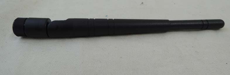
1-1. FRONT External Photo 1-2. REAR 1-3.top of side 1-4.bottom of side 1-5.left of side 1-6.right of side 1-7 REAR ( Antenna connection) Antenna(24/58)GHzAntenna (2.4/5.8)GHz
ID Label/Location Info
1.Internal of product Label of Photo
Internal Photos
INTERNAL PHOTO 1. ADAPTER 1.1 Front 1.2 Rear 1.3 lable 2. MAIN BOARD 2.1 Front 2.2 Rear 3. Front BOARD 3.1 Front3.1 Front 3.2 Rear 4. RF BOARD 4.1 Front 4.2 Rear 5. Inside 6.RF Moduie connection RF MODULE RF MODULE 1 RF MODULE 2 RF MODULE 1RF MODULE1 RF MODULE2RF MODULE 2
RF Exposure Info
RF Exposure Measurement 1. Introduction 2. Classification MODE: Wi-Fi Binary CDMA 3. RF Exposure Limit Magnetic Field Strength(A/m) Power Density (mW/cm 2 ) Average Time (minutes) 1.63 * (100) 6 4.89/f * (900/f 2 ) 6 0.1631.06 -f/3006 -56 Magnetic Field Strength(A/m) Power Density (mW/cm 2 ) Average Time (minutes) 1.63 * (100) 30 2.19/f * (180/f 2 ) 30 0.0730.230 -F/150030 -1.030 F = Frequency in MHz * = Plane-wave equivalent power density 824/f Frequency Range (MHz) 61.4 (B) Limits for General Population/Uncontrolled Exposure The maximum Gain measured in Fully Anechoic Chamber is 2.4G 3.6972 , 5G 4.8885 dBi or 2G 2.343 , 5G 3.082 (numeric). 30 - 300 300 - 1500 1500 - 100,000- 0.3 - 1.34614 1.34 - 30 - LIMITS FOR MAXIMUM PERMISSIBLE EXPOSURE (MPE) Electric Field Strength (V/m) 30 - 300 - - 1500 - 100,000 Electric Field Strength (V/m) 0.3 - 3.0614 (A) Limits for Occupational/Controlled Exposures Frequency Range (MHz) 3.0 - 301842/f Because this deivce is transmitting the high power signal, it is regarded specially as a dangerous band for its heating harmfulness to the human body. The manufacturer whose product is working in this frequency band is obligatory to prove the harmfulness of his product. In this document, we try to prove the safety of radiation harmfulness to the human body for our product. The limit for Maximum Permissible Exposure (MPE) specified in FCC 1.1310 is followed. The Gain of the antenna used in this product is measured in a Fully Anechoic Chamber (FAC), and the maximum total power input to the antenna is measured. Through the Friis transmission formula and the maximum gain of the antenna, we can calculate the distance, away from the product, where the limit of MPE is reached. Page 1 of 3 The antenna of the product, in normal use condition, this devices used more than 20 cm from the user. According to FCC 1.1310: The criteria listed in the following t able shall be used to evaluate the environmental impact of human exposure to radio-frequency(RF) radiation as specified in 1.1307(b). 300 - 1500 27.5 4. Friis Formula Friis transmission formula : P d = (P out *G) / (4*π*r 2 ) P out = output power to antenna in mW G = gain of antenna in linear scale Pi = 3.1416 MODE: Wi-Fi Binary CDMA r=distance between observation point and center of the radiator Page 2 of 3 The software provided by Manufacturer enabled the EUT to transmit with max power at lowest, middle and highest channel individually. Pd is the limit of MPE, 1mW/cm 2 . If we know the maximum Gain of the antenna and the total power input to the antenna, through the calculation, we will know the distance r where the MPE limit is reached. The maximum Gain measured in Fully Anechoic Chamber is 2.4G 3.6972 , 5G 4.8885 dBi or 2G 2.343 , 5G 3.082 (numeric). 5. Test Results 5.1 Antenna Gain 5.2 Output Power into Antenna & RF Exposure value ANT1 Channel Channel Frequency (MHz) Output Power to Antenna (mW) Power Density (mW/cm 2 ) Limit of Power Density (mW/cm 2 ) LOW2410.00209.0000.0974201.0 MID2442.00203.0000.0946231.0 HI2474.00239.0000.1114041.0 Channel Channel Frequency (MHz) Output Power to Antenna (mW) Power Density (mW/cm 2 ) Limit of Power Density (mW/cm 2 ) LOW5735.0051.0000.0312701.0 MID5785.0056.0000.0343361.0 HI5815.0046.0000.0282051.0 ANT2 Channel Channel Frequency (MHz) Output Power to Antenna (mW) Power Density (mW/cm 2 ) Limit of Power Density (mW/cm 2 ) LOW2410.00236.0000.1100051.0 MID2442.00269.0000.1253871.0 HI2474.00213.0000.0992841.0 Channel Channel Frequency (MHz) Output Power to Antenna (mW) Power Density (mW/cm 2 ) Limit of Power Density (mW/cm 2 ) LOW5735.0052.0000.0318831.0 MID5785.0055.0000.0337231.0 HI5815.0043.0000.0263651.0 Page 3 of 3 The maximum Gain measured in Fully Anechoic Chamber is 2.4G 3.6972 , 5G 4.8885 dBi or 2G 2.343 , 5G 3.082 (numeric).
Test Setup Photos
1. Photographs of test setup 1-1.Setup for Radiated Test : 30 ~ 1 000 MHz [ Front ] TEST SETUP PHOTO [ Rear ] 1-2. Setup for Radiated Test :Above 1 000 MHz [ Front ] [][ Rear ] 1-3. Setup for Conducted Test : 0.15 ~ 30 MHz [ Front ] [ Rear ]
Contact Information
Applicant
Hyuk Jin Lee(Manager)
Technical Contact
EstechJinho Kim
[email protected]82316318037
97-1, Hoeeok-ri, Majang-myeon, · Icheon-si, Gyeonggi-do, · South Korea
Non-Technical Contact
EstechJinho Kim
[email protected]82316318037
Test Firm
ESTECH CO., LTDJin Mo Yang
Technical Specifications
| # | Rule Parts | Frequency Range | Power Output |
|---|---|---|---|
| 2 | 15C | 5.74 GHz - 5.82 GHz | 56.00 mW |
Other Applications from EMW Co.,Ltd
2ABUYBHA-WC100
Apr 30, 2014Binary CDMA Compliant
Equipment Class
DTS - Digital Transmission System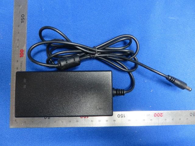
2ABUYBHA-WN402
Apr 29, 2014NVR(Network Video Recorder)
Equipment Class
DXX - Part 15 Low Power Communication Device Transmitter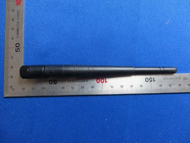
2ABUYBHA-WC102
Apr 29, 2014IPC (IP Camera)
Equipment Class
DXX - Part 15 Low Power Communication Device Transmitter