2ABVK373372Mobile Mesh Networking Device
goTenna Inc.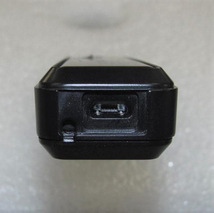
Click to zoom
Application Details
- Equipment Class
- DXX - Part 15 Low Power Communication Device Transmitter
- Date of Grant
- Mar 22, 2023
- Application Purpose
- Original Equipment
- Date of Application
- Mar 22, 2023
- Equipment Note
- Mobile Mesh Networking Device
- Frequency Range
- 2402.00000000 - 2480.00000000
- Company
- goTenna Inc.
- Country
- United States
Documents & Files
Document Text
Text extracted from the exhibit documents filed with the FCC. Open a document above to read the original.
Users Manual
Part Number 900-00202 • Part Number 900-00212 • Part Number 900-00207 goTenna Pro X2 Part Number 37337-X2 User Guide Version 2.2 03/2023 Welcome Flexible Deployment Options goTenna Pro Deployment Kit goTenna Pro Management Portal goTenna Pro App goTenna Pro X Quickstart Guide for ATAK Plug-In Support / Legal 1 2 3 17 29 49 75 User Guide Table of Contents Version 2.2 03/2023 Version 2.2 03/2023 Welcome to your goTenna Pro Deployment Kit The Pro Deployment Kit, or goKit, is a powerful part of the goTenna Pro ecosystem that enables you to rapidly deploy a mesh network when deployed off-grid. It serves several key functions: • Storage container for up to 30 goTenna Pro or Pro X radios, and antennas • Charging dock for up to 30 goTenna Pros • Deployment computer and WiFi hotspot to rapidly distribute frequencies and apps to users The goTenna Radios included in this goKit are mesh networking data radios that facilitate situational awareness and communications using the goTenna Pro app or ATAK via the goTenna Pro X plugin. With the goTenna Pro app or goTenna ATAK plugin installed on the End User Device (EUD) or smartphone, the EUD will pair to the goTenna Pro radio to provide location, text-based messages, and more. The goTenna then broadcasts this info to other users on the network via VHF or UHF transmissions. In order for the goTenna Pro to successfully communicate to other goTenna Pros on the network, all radios must be tuned to the same frequency set. The EUD manages frequency sets and tunes the goTenna accordingly via the app. Your goKit can help facilitate distribution of frequency sets to end users. This is done either in conjunction with the goTenna Management portal or as a stand alone device without any internet connection. goKit Deployment: Sync with the Portal When used in conjunction with the online portal, your organization’s admin can login to the online portal to manage frequency sets and users. The goKit then syncs to the portal when an internet connection is available so that it can fetch and store this data locally. It is then ready to move to an offline environment where it can deploy end users by sending frequencies to the goTenna app/plugin over the built-in WiFi hotspot or QR code. goKit Deployment: Offline Deployment If you choose not to manage frequencies online or do not have an internet connection available, you may enter a frequency set directly into the goKit and then deploy via the built-in WiFi hotspot or via QR code. Deploying without the goKit Using a goKit to deploy is not required. End users may log into their goTenna app or plugin if an internet connection is available. End user accounts are set up by your organization’s admin in the management portal. It is recommended that users log into their app before deployment in the event they deploy to an area without internet service. Additionally, end users may manually enter frequencies into the app without needing to sign into the app or sync with a goKit. 1Welcome Welcome Version 2.2 03/2023 goTenna Pro provides flexible deployment options depending on your team’s mission set and operating environment. Initial frequency setup and device configuration can be supported with or without an internet connection. Create and assign frequency sets to designated user or group accounts. Download frequency sets directly to smartphone app and paired goTenna device. Enter frequency sets into smartphone app. Generate a unique QR code. Share frequency sets with other phones and paired devices by scanning QR code. Enter frequency sets, apps, and data packages into goKit. Generate a unique QR code or turn on WIFI-enabled hotspot with goKit. Download frequency sets, apps, and data packages directly to EUD. Generate a unique QR code or turn on WIFI-enabled hotspot with goKit. Download frequency sets, apps, and data packages directly to EUD. Create and assign frequency sets to designated user or group accounts. Download frequency sets, apps, and data packages directly to goKit. Bring goKit off-grid. Deployment Kit Options goTenna Deployment Kits (or “goKits”) store and charge up to 30 Pro or Pro X devices, allowing large teams to deploy more rapidly with the online portal or fully offline in the field. In addition to frequency set configuration, internal goKit hotspots can also support initial application downloads and regular software updates in off-grid environments. Device-Only Options For teams preparing for operations in advance, goTenna’s online management portal provides extra convenience and ease-of-use for system administrators. When Internet access isn’t available, goTenna Pro and Pro X users can still adjust frequency settings off-grid using previously downloaded smartphone applications. Online Offline 2Flexible Deployment Options Flexible Deployment Options Version 2.2 03/2023 User Guide Table of Contents goKit Features goKit Onboarding Portal Login Onboarding Offline Mode Onboarding Home Page Mode Hot-Spot Settings Frequency Sets Mission Packs Applications Update Firmware 4 6 6 7 7 8 9 13 15 16 Deployment Kit User Guide3 Version 2.2 03/2023 Key Features Device Maintenance - Charge, transport, and automatically execute radio updates. Cloud Sync - Automatically syncs with the goTenna Pro Management Portal to ensure all software is up-to-date via synchronization with the Management Portal. Mobile Application Deployment - Wirelessly install any application to your Android device completely off-grid. Power Bank - Integrated rechargeable power offering 99Wh of auxiliary power. Flexible storage - Two integrated storage containers for carrying antennas, satellite backhaul stations, or anything else needed. Touchscreen - Included 7-inch Touch Screen display for intuitive and rapid operation. A/C & Auxiliary Power - Accepts A/C (Part #900-00202 accepts 110v and Part #900-00212 accepts 110V-240V) and 12V DC auxiliary external power sources for operation and long-term storage. 1 2 4 5 11 10 8 9 7 6 3 Get to know your goKit 1. 7-in…
Text truncated - open the document above for the full version.
Attestation Statements
Date: 2/3/2023 Federal Communications Commission 7435 Oakland Mills Road Columbia, MD 21046 USA Ref: Attestation Statements Part 2.911(d)(5)(i) Filing FCC ID 2ABVK373372 To whom it may concern, goTenna Inc. (“the applicant”) certifies that the equipment for which authorization is sought is not “covered” equipment prohibited from receiving an equipment authorization pursuant to section 2.903 of the FCC rules. Sincerely, Dean Mason Sr. Product Mgr Federal Communications Commission Authorization and Evaluation Division 7435 Oakland Mills Road Columbia, MD 21046 USA Date: 2-3-2023 Ref: Attestation Statements Part 2.911(d)(5)(ii) Filing FCC ID: 2ABVK373372 goTenna Inc., (“the applicant”) certifies that, as of the date of the filing of the application, the applicant is not identified on the Covered List as an entity producing “covered” equipment. Sincerely, Dean Mason Sr. Product Mgr.
Attestation Statements
Test Lab Attestation Letter Date of Test: January 23 thru February 20, 2023 Applicant Name: goTenna, Inc. FCC ID: 2ABVK373372 Test Item: goTenna PRO Model: 37337-X2 Name of Engineer Performing Test: Joseph Strzelecki, Chris D’Alessio Radiometrics Midwest Corporation Statement of Compliance: Radiometrics declares that this Unit has been tested in accordance with the test method identified in this test report and that we observed it being tested. We also declare that the Unit complies with the relevant limits. All instrumentation and accessories used to test this unit for compliance to the indicated test method are calibrated regularly in accordance with ISO 17025:2005 requirements by laboratories accredited by A2LA, NVLAP, or ACLAS for the measurement parameters. The measurements were made at: Radiometrics Midwest Corporation 12 Devonwood Avenue Romeoville IL 60446 Test Lab Witness- Joseph Strzelecki Signature of Test Lab Witness: Full Name, Typed: Joseph R Strzelecki Title of Witness: Senior EMC Engineer Email Address: [email protected] Phone No.: 815-293-0772 Test Lab Stamp:
Attestation Statements
FRN #: 0022973614
Cover Letter(s)
Federal Communications Commission Authorization and Evaluation Division 1435 Oakland Mills Road Columbia, MD 21046 Innovation, Science, and Economic Development Canada Certification and Engineering Bureau P.O. Box 11490, Station ‘H’ 3701 Carling Ave., Building 94 Ottawa, Ontario K2H 8S2 Canada Date: SUBJECT: FCC Application for FCC ID: 2ABVK373372 IC: 21842-373372 To Whom It May Concern: We, the undersigned, hereby authorize Joseph Strzelecki of Radiometrics Midwest Corp at 12 Devonwood Ave, Romeoville, IL 60446 on our behalf, to apply to the Federal Communications Commission (FCC) and Innovation, Science, and Economic Development Canada (ISED) on our equipment. Any and all acts carried out by Radiometrics on our behalf shall have the same effect as acts of our own. This is to advise that we are in full compliance with the Anti-Drug Abuse Act. We, the applicant, are not subject to a denial of federal benefits pursuant to Section 5301 of the Anti-Drug Act of 1988, 21 USC853a, and no party to the application is subject to a denial of federal benefits pursuant to that section. This authorization is valid until further written notice from the applicant. Regards, Dean Mason Sr. Product Mgr. goTenna Inc.
Cover Letter(s)
Page 1 of 1 RP-9748L 12 Devonwood Ave SOLVING A WAVE OF EMI COMPLIANCE PROBLEMS Romeoville, IL 60446 March 6, 2023 Tel: (815) 293-0772 Page 1 of 1 Fax: (815) 293-0820 Federal Communications Commission Authorization and Evaluation Division 7435 Oakland Mills Rd. Columbia, MD 21046 Organization: goTenna, Inc. Confidentiality Request regarding application for certification of FCC ID: 2ABVK373372 Pursuant to Sections 0.457 and 0.459 of the Commission’s Rules, we hereby request confidential treatment of information accompanying this application as outlined below: Exhibit Type File Name Circuit Schematics 7 Schematic PRO-X2 Block Diagram 8 goTenna PRO Block Diagram EUT description (Operational Description) 10a goTenna Operational Description PRO-X2 Parts List 14 goTenna PRO X2 Parts List 9748 The above materials contain trade secrets and proprietary information not customarily released to the public. The public disclosure of these materials may be harmful to the applicant and provide unjustified benefits to its competitors. The applicant understands that pursuant to Section 0.457 of the Rules, disclosure of this application and all accompanying documentation will not be made before the date of the Grant for this application. Authorized Signature Joseph Strzelecki Senior EMC Engineer Radiometrics Midwest Corporation Authorized Agent for goTenna, Inc.
Cover Letter(s)
Page 1 of 1 RP-9748 12 East Devonwood SOLVING A WAVE OF EMI COMPLIANCE PROBLEMS Romeoville, IL 60446 Tel: (815) 293-0772 Fax: (815) 293-0820 March 1, 2023 Federal Communications Commission Authorization and Evaluation Division 7435 Oakland Mills Rd. Columbia, MD 21046 Reference FCC ID: 2ABVK373372 Organization: goTenna, Inc. 81 Willoughby St. Brooklyn, NY 11201 Subject: Frequency Justification Attestation goTenna, Inc. acknowledges that this device will not be marketed to USA users with frequency bands which are not allowed by rule part 90, and that it is a violation of FCC rules if this device is operated on unauthorized frequencies inside the United States. goTenna, Inc. acknowledges that this equipment meets the requirement of FCC Rules, Part 90.203(g)(3). Programming of this product’s transmit frequencies can be performed only by the manufacturer or by authorized service or maintenance personnel. This equipment can only be programmed for frequencies through use of external devices or specifically programmed modules made available only to authorized service or maintenance personnel, not the end user or the general public. This transmitter operates in the following frequency ranges: Band/Mode Frequency ranges FCC rule parts UHF 450 - 479 MHz 90 Aclara Technologies is requesting that the FCC lists the above applicable frequency range under FCC Rule Part 90 on the FCC Grant. For the FCC’s Rule Part 90 application, this radio is used in public utilities as indicated in the table below. This device complies with 47 CFR Part 90.203(e), the end user cannot program the transmit frequencies, since it is a sealed device. Per the FCC’s KDB634817 guidance, as an alternative to listing the exact frequencies, we acknowledge that it is a violation of the FCC Rules if this device operates on unauthorized frequencies. Frequency Range (MHz) Part 90 450-454 X 454-456 456-460 X 460-462.5375 X 462.5375-462.7375* 462.7375-467.5375 X 467.5375-467.7375 X 467.7375-479 X * Canada This device will only be used in the designated Frequency Ranges above that are marked with an X. Authorized Signature Joseph Strzelecki Senior EMC Engineer Radiometrics Midwest Corporation Authorized Agent for goTenna, Inc.
External Photos
Page 1 of 4 RP-9748 External EUT Photographs Front of EUT Page 2 of 4 RP-9748 Rear of EUT Page 3 of 4 RP-9748 Sides of EUT Page 4 of 4 RP-9748 Bottom of EUT Top of EUT
ID Label/Location Info
Page 1 of 2 RP-9748 ID Label/Location Drawing/Photograph showing placement of Label Radiometrics Midwest Corporation (815) 293-0772 – [email protected] Drawing of label The Label is laser etched onto the back of the EUT. The label measures 2 cm wide by 2.5 cm tall
Internal Photos
Page 1 of 3 RP-9748 Internal EUT Photographs Photograph of PC Board: Top Side Page 2 of 3 RP-9748 Bottom Side Page 3 of 3 RP-9748 Photograph of EUT: Cover removed
Parts List/Tune Up Info
Tune up Procedures The UHF/VHF module does not contain any mechanically or electrically adjustable parts in the transmitter RF path, so there is no tune up procedure for the transmitter. The transmit power and transmit frequency are set via embedded firmware commands that the microprocessor provides to the radio upon power-up. These settings require special software to adjust and are inaccessible to the end user. goTenna, Inc. low power RF devices have passed through extensive testing and calibration procedures while in the factory. Therefore, no additional calibration or adjustment is required in the field. Minimum: conducted power: 150-173.3 MHz: 0.7dBm. Nominal: conducted power: 150-173.3 MHz: 37.0 dBm Maximum: conducted power: 150-173.3 MHz: 37.0 dBm Tune up Tolerance: 150-173.3 MHz: 0.35 dB Minimum: conducted power: 450-479 MHz: 0.7dBm. Nominal: conducted power: 450-479 MHz: 37.0 dBm Maximum: conducted power: 450-479 MHz: 37.0 dBm Tune up Tolerance: 450-479 MHz: 0.35 dB
RF Exposure Info
© 2023 RF Exposure Lab, LLC This report shall not be reproduced except in full without the written approval of RF Exposure Lab, LLC. 802 N. Twin Oaks Valley Road, Suite 105 • San Marcos, CA 92069 • U.S.A. TEL (760) 471-2100 • FAX (760) 471-2121 http://www.rfexposurelab.com CERTIFICATE OF COMPLIANCE SAR EVALUATION GoTenna, Inc. Dates of Test: February 27-March 1, 2023 81 Willoughby St. Test Report Number: SAR.20230301 Brooklyn, NY 11201 Revision B Lab Designation Number: US1195(FCC); US1094(ISED) This wireless mobile and/or portable device has been shown to be compliant for localized specific absorption rate (SAR) for controlled environment/occupational exposure limits specified in ANSI/IEEE Std. C95.1-1992 and had been tested in accordance with the measurement procedures specified in IEEE 1528- 2013 and IEC 62209-1528:2020 (See test report). I attest to the accuracy of the data. All measurements were performed by myself or were made under my supervision and are correct to the best of my knowledge and belief. I assume full responsibility for the completeness of these measurements and vouch for the qualifications of all persons taking them. RF Exposure Lab, LLC certifies that no party to this application is subject to a denial of Federal benefits that includes FCC benefits pursuant to Section 5301 of the Anti-Drug Abuse Act of 1988, 21 U.S.C. 853(a). Jay M. Moulton Vice President Testing Cert. # 2387.01 FCC ID: 2ABVK373372 IC Certificate: 21842-373372 Model(s): 37337-X2 Test Sample: Engineering Unit Same as Production Serial Number: 015 Equipment Type: Wireless Texting Device Classification: Portable Transmitter Next to Body TX Frequency Range: 150 – 174 MHz; 450 – 479 MHz Frequency Tolerance: ± 2.5 ppm Maximum RF Output: 150 MHz – 37.0 dBm; 450 MHz – 37.0 dBm Conducted Signal Modulation: FM Antenna Type: External Application Type: Certification FCC Rule Parts: Part 2, 90 KDB Test Methodology: KDB 447498 D01 v06 Industry Canada: RSS-102 Issue 5, Safety Code 6 Maximum SAR Value: 4.32 W/kg Reported Max. Simultaneous SAR: 4.36 W/kg Reported Separation Distance: 0 mm Report Number: SAR.20230301 © 2023 RF Exposure Lab, LLC Page 2 of 86 This report shall not be reproduced except in full without the written approval of RF Exposure Lab, LLC. Table of Contents 1. Introduction ........................................................................................................................ 4 SAR Definition [5] ................................................................................................................... 5 2. SAR Measurement Setup ................................................................................................... 6 Robotic System ...................................................................................................................... 6 System Hardware ................................................................................................................... 6 System Electronics ................................................................................................................. 7 Probe Measurement System .................................................................................................. 7 3. Probe and Dipole Calibration .............................................................................................15 4. Phantom & Simulating Tissue Specifications .....................................................................16 Head & Body Simulating Mixture Characterization ................................................................16 5. ANSI/IEEE C95.1 – 1992 RF Exposure Limits [2] ..............................................................17 Uncontrolled Environment .....................................................................................................17 Controlled Environment .........................................................................................................17 6. Measurement Uncertainty .................................................................................................18 7. System Validation..............................................................................................................19 Tissue Verification .................................................................................................................19 Test System Verification ........................................................................................................19 8. SAR Test Data Summary ..................................................................................................20 Procedures Used To Establish Test Signal ...........................................................................20 Device Test Condition ...........................................................................................................20 SAR Data Summary – 150 MHz Body ...................................................................................22 SAR Data Summary – 450 MHz Body ...................................................................................23 SAR Data Summary – Simultaneous Evaluation ...................................................................24 9. Test Equipment List ...........................................................................................................25 10. Conclusion ....................................................................................................................26 11. References ....................................................................................................................27 Appendix A – System Validation Plots and Data .......................................................................28 Appendix B – SAR Test Data Plots ...........................................................................................31 Appendix C – SAR Test Setup Photos ......................................................................................34 Appendix D – Pr…
Text truncated - open the document above for the full version.
Test Report
Ordering Part # 1003893FT-AA10L0100 Dimensions (mm)40.0 x 8.0 x 0.12 Weight (grams)0.7 Cable/Connector (mm) Length: 100, Diameter: 1.13, Color: Black; u.Fl compatible connector Mountingusing3M468Adhesive PackagingPE bags BT Tunable FPC 2.4 GHz Embedded Antenna with cable DATASHEET Part No. 1003893FT Product: BT Tunable FPC 2.4 GHz Embedded Antenna 5/22/2020Proprietary www.ethertronics.com Electrical Specifications Typical Performance using 100 mm cable tested on PC-ABS Mechanical Specifications KEY BENEFITS Stay-in-Tune Ethertronics antenna technology provides superior RFfield containment, resulting in less interaction with surrounding components. Quicker Time-to-Market By optimizing antenna size, performance and emissions, customer and regulatory specifications are more easily met. Reliability Products are the latest RoHS version compliant APPLICATIONS •Embedded design •Cellular, Headsets, Tablets •Gateway, Access Point •Handheld •Telematics •Tracking •Healthcare •M2M, Industrial devices •Smart Grid •OBD-II Part No. 1003893FT BT Tunable FPC 2.4 GHz Embedded Antenna 2.4 GHz Supports: Wi-Fi applications, Agriculture, Automotive, Bluetooth, Zigbee, WLAN, Smart Home, Healthcare, Digital Signage 2.400 –2.485 GHz Ethertronics’ WLAN antennas deliver on the key needs of device designers for higher functionality and performance in smaller/thinner designs. These innovative antennas provide compelling advantages for 2.4 GHz enabled devices. Real-World Performance and Implementation Antennas may look alike on the outside, but the important difference is inside. Other antennas may contain simple PIFA or monopole designs that interact with their surroundings, complicating layout or changing performance with use position. Ethertronicsantennas utilize patented Isolated Magnetic Dipole (IMD) technology to deliver a unique size and performance combination. This antenna is also offered in PCB form under PN# 1003893PT. The 1003893FT is offered in many standard cable lengths ranging up to 200 mm. Ordering part number guide is located at end of document for selection ease. Frequency2.400 –2.485 GHz Peak Gain3.3 dBi Average Efficiency87% VSWR Match1.5:1 max Feed Point Impedance50 ohms unbalanced PolarizationLinear Power Handling0.5 Watt CW *Additional variations with different cable lengths, colors and connectors are available. © 2020 Ethertronics tel +(1) 858.550.3820 | fax +(1) 858.550.3821 email: [email protected] 5501 Oberlin Drive, Suite 100 San Diego, CA 92121 -USA Typical VSWRand Efficiency Plots Measured in free space with PC/ABS loading and 100 mm cable EfficiencyVSWR Test Setup and Antenna Assembly Measured in free space with PC/ABS loading and 100 mm cable Y X Z Antenna assembly Antenna Radiation Patterns Measured with PC/ABS loading and 100 mm cable Typical Performance @ 2440 MHZ 2.4 GHz Ethertronics’ Embedded Antenna Specifications Ethertronics produces a wide variety of standard and custom antennas to meet user needs. DATASHEET | Part No. 1003893FT © 2020 Ethertronics tel +(1) 858.550.3820 | fax +(1) 858.550.3821 email: [email protected] 5501 Oberlin Drive, Suite 100 San Diego, CA 92121 -USA Antenna Tuning Options Typical Performance using 100 mm cable tested on PC-ABS Options for Tuning: "2.4GHz (Lower)" Ref Default: P1 ~ P8 Open *This antenna has unique features enabling limited range RF tuning by leaving P1 ~ P8 connected by “solder bridge”. Refer to detailed tuning options below. MODET1T2T3T4 PADS Connect: P1+P5 Connect: P1+P2+P5+P6 Connect: P3+P7 Connect: P3+P4+P7+P8 Outcome: (Ref: Default) ~20 MHz Shift low ~40 MHz Shift low ~20 MHz Shift low ~50 MHz Shift low 2.4 GHz Ethertronics’ Embedded Antenna Specifications Ethertronics produces a wide variety of standard and custom antennas to meet user needs. DATASHEET | Part No. 1003893FT P1 P2 P3 P4 P8 P7 P6 P5 Antenna Tuning Procedure This antenna has unique features enabling limited range RF tuning by adding a solder bridge in the designated area. Ease of tuning for any application on the fly with a soldering iron. Tuning optional if required. Antenna Tuning (Low) *Add bridge of solder to connect pads for tuning Filled Gap © 2020 Ethertronics tel +(1) 858.550.3820 | fax +(1) 858.550.3821 email: [email protected] 5501 Oberlin Drive, Suite 100 San Diego, CA 92121 -USA Mechanical Dimensions For references only, in mm. 2.4 GHz Ethertronics’ Embedded Antenna Specifications Ethertronics produces a wide variety of standard and custom antennas to meet user needs. Part NumberA (mm)B (mm)C (mm)D (mm)Connector 1003893FT-AA10L0100 40.0 ±0.38.0 ±0.30.12100.0 ±3.0 u.FLcompatible DATASHEET | Part No. 1003893FT *Height “C” of 0.12 mm includes FPC + adhesive thicknesses *Connector shown in photo below is “Face Down” Front View A B D Side View C Back View © 2020 Ethertronics tel +(1) 858.550.3820 | fax +(1) 858.550.3821 email: [email protected] 5501 Oberlin Drive, Suite 100 San Diego, CA 92121 -USA Ordering Part Numbers Typical antenna dimensions (mm) 2.4 GHz Ethertronics’ Embedded Antenna Specifications Ethertronics produces a wide variety of standard and custom antennas to meet user needs. Part NumberA (mm)B (mm)C (mm)D (mm)Connector 1003893FT-AA10L0025 40.0 ±0.38.0 ±0.30.1225.0 ±3.0 u.FLcompatible 1003893FT-AA10L0050 40.0 ±0.38.0 ±0.30.1250.0 ±3.0 u.FLcompatible 1003893FT-AA10L0075 40.0 ±0.38.0 ±0.30.1275.0 ±3.0 u.FLcompatible 1003893FT-AA10L0100 40.0 ±0.38.0 ±0.30.12100.0 ±3.0 u.FLcompatible 1003893FT-AA10L0150 40.0 ±0.38.0 ±0.30.12150.0 ±4.0 u.FLcompatible 1003893FT-AA10L0200 40.0 ±0.38.0 ±0.30.12200.0 ±4.0 u.FLcompatible DATASHEET | Part No. 1003893FT *Height “C” of 0.12 mm includes FPC + adhesive thicknesses *Connector shown in photo below is “Face Down” Mouser Electronics Authorized Distributor Click to View Pricing, Inventory, Delivery & Lifecycle Information: Kyocera AVX: 1003893FT-AA10L0075 1003893FT-AA10L0100 1003893FT-AA10L0150 1003893FT-AA10L0200 1003893FT- AA10L0025 1003893FT-AA10L0050
Test Report
Electromagnetic Compatibility Test Report Tests Performed on a GoTenna, Inc. Conductor Sensor Transceiver, Model 37337-X2 Radiometrics Document RP-9748B Product Detail: FCC ID: 2ABVK373372 IC: 21842-373372 Equipment type: Low power 2.4 GHz transceiver Test Standards: US CFR Title 47, Chapter I, FCC Part 15 Subpart C FCC Part 15 CFR Title 47: 2023 Canada ISED; RSS-210, Issue 10 as required for Category I Equipment IC RSS-GEN Issue 5 This report concerns: Original Grant for Certification FCC Part 15.249 Tests Performed For: Test Facility: GoTenna, Inc. 81 Willoughby St. Brooklyn, NY 11201 Radiometrics Midwest Corporation 12 Devonwood Avenue Romeoville, IL 60446-1349 (815) 293-0772 Test Date(s): January 19 to February 4, 2022 Document RP-9748B Revisions: Rev. Issue Date Revised By 0 March 6, 2023 Test Report for the goTenna, Inc. goTenna Pro, Model 37337-X2 RP-9748B Rev. 0 Radiomet.com Page 2 of 18 Table of Contents 1.0 ADMINISTRATIVE DATA ............................................................................................................... 3 2.0 TEST SUMMARY AND RESULTS ................................................................................................. 3 2.1 RF Exposure Compliance Requirements .................................................................................... 3 3.0 EQUIPMENT UNDER TEST (EUT) DETAILS ................................................................................ 4 3.1 EUT Description .......................................................................................................................... 4 3.1.1 FCC Section 15.203 & RSS-GEN Antenna Requirements .................................................... 4 4.0 TESTED SYSTEM DETAILS .......................................................................................................... 4 4.1 Tested System Configuration ...................................................................................................... 4 4.2 EUT Operating Modes ................................................................................................................ 4 4.3 Special Accessories .................................................................................................................... 4 4.4 Equipment Modifications ............................................................................................................. 5 5.0 TEST SPECIFICATIONS ............................................................................................................... 5 6.0 TEST PROCEDURE DOCUMENTS ............................................................................................... 5 7.0 RADIOMETRICS’ TEST FACILITIES ............................................................................................. 5 8.0 DEVIATIONS AND EXCLUSIONS FROM THE TEST SPECIFICATIONS ...................................... 6 9.0 CERTIFICATION ............................................................................................................................ 6 10.0 TEST EQUIPMENT TABLE .......................................................................................................... 6 11.0 TEST SECTIONS ......................................................................................................................... 7 11.1 AC Conducted Emissions ......................................................................................................... 7 11.2 Radiated RF Emissions............................................................................................................. 9 11.2.1 Field Strength Calculation .....................................................................…
Text truncated - open the document above for the full version.
Contact Information
Applicant
Dean Mason(Sr. Product Mgr)
Test Firm
Radiometrics Midwest Corp.Joseph Strzelecki
Technical Specifications
| # | Rule Parts | Frequency Range | Power Output |
|---|---|---|---|
| 1 | 15C | 2.40 GHz - 2.48 GHz | - |