2ABVM-ELECHNFCV4PN532 NFC BOARD
HK ELECHOUSE ELECTRONICS TECHNOLOGY CO., LIMITED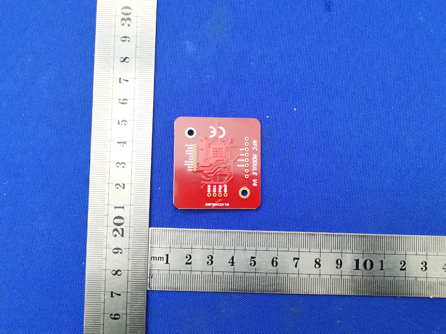
Click to zoom
Application Details
- Equipment Class
- DXX - Part 15 Low Power Communication Device Transmitter
- Date of Grant
- Jan 28, 2021
- Application Purpose
- Original Equipment
- Date of Application
- Jan 28, 2021
- Equipment Note
- PN532 NFC BOARD
- Frequency Range
- 13.56000000 - 13.56000000
- Country
- Hong Kong
Documents & Files
Document Text
Text extracted from the exhibit documents filed with the FCC. Open a document above to read the original.
Users Manual
www.elechouse.com PN532 NFC RFID Module User Guide Version V4 Introduction N ear field communication (NFC) is a set of standards for smartphones and similar devices to establish radio communication with each other by touching them together or bringing them into close proximity, usually no more than a few centimeters. For electronics geeks, we also want to use NFC technology to make our own things. So we build this NFC RFID module. This module is built around NXP PN532. NXP PN532 is very popular in NFC area. And the company offers much technology documents to help developers. We developed this module based on the official documents. To make things easier, we also build library for this module. www.elechouse.com We have updated this module to version 4. Compared with V3 have the following improvement: Performance PN532 NFC V3 PN532 NFC V4 Description Reading Distance on PVC Mifare tag 5~6cm 6~8cm Improved performance on IOS14443A tags Reading Distance on PVC SRT512 1~2cm 2~4cm Improved performance on IOS14443B tags Feature 1. Compatibility: it is compatible with V3 both in hardware and software. 2. Smaller: the size now is as small as 42.7mm*40.4mm*4mm 3. Easy to change mode: with a small SMD toggle Switch, it becomes very easy to change among IIC, SPI and HSU modes 4. Longer distance: the reading distance becomes 6~8cm www.elechouse.com 5. Open source Arduino library Features 1. Support II2, SPI and HSU (High Speed UART) 2. RFID reader/writer mode support • Mifare 1k, 4k, Ultralight, and DesFire cards • ISO/IEC 14443-4 cards such as CD97BX, CD light, DesFire, P5CN072 (SMX) • Innovision Jewel cards such as IRT5001 card • FeliCa cards such as RCS_860 and RCS_854 3. Plug and play, Arduino compatible 4. Built in PCB Antenna, with 6cm~8cm communication distance 5. On-board level shifter, Standard 5V TTL for I2C and UART, 3.3V TTL SPI 6. Work as RFID reader/writer 7. Work as 1443-A card or a virtual card 8. Support NFC with Android phone 9. Small size: 43mm*41mm*4mm Interface • VCC: 3.3V~5V • Currency: Max 120mA www.elechouse.com • I2C/UART: 3.3V~24V TTL • SPI: 3.3V TTL with 100 ohm resistors in series. It could be connected directly to 5V interface of microcontroller such as Arduino. The I2C and HSU shares the same pins. The definition of IIC pins is printed at front and the HSU’s is printed at the back. The HSU mode is configured as the default mode. But you could change the interface by setting the toggle switch. The switch setting is shown as follows: Working Interface Channel 1 Channel 2 HSU OFF OFF I2C ON OFF SPI OFF ON We break all the PN532 pins out. The 1.27mm connector hole contains those pins which might not be used for most users. If some developers need to connect those pins, we could supply connectors. You could find this product here. Hardware Installation Solder the connector The bended male pins come with the NFC board. www.elechouse.com Some users might need soldering other types of connectors or directly solder wires on it. Anyway, make sure the wires go across the antenna lines in 90 degree. www.elechouse.com Connect with Arduino If without the sensor shield, please connect as following: Mode PN532 Module Arduino UNO Arduino Leonardo Arduino Mega (2560) Arduino Due Power VCC 5V 5V 5V 5V GND GND GND GND GND IIC/I2C Mode SDA A4/SDA Pin 2 /SDA Pin 20 /SDA Pin 20 /SDA SCL A5/SCL Pin 3/SCL Pin 21/SCL Pin 21/SCL HSU Mode TXD Pin 0 Could not present message in Serial Monitor on PC Pin 0 Pin 19 Pin 19 RXD Pin 1 Pin 1 Pin 18 Pin 18 SPI Mode SCK Pin 13 or ICSP-3 ICSP-3 Pin 52 or ICSP-3 ICSP-3 Note: SPI on Due is still in developing MISO Pin 12 or ICSP-1 ICSP-1 Pin 50 or ICSP-1 ICSP-1 MOSI Pin 11 or ICSP-4 ICSP-4 Pin 51 or ICSP-4 ICSP-4 SS Pin 10 Pin 10 Pin 10 Pin 10 Arduino UNO only has one serial interface which is also connected to USB port to PC. In HSU mode, the serial monitor could not be used as message displaying windows. Function Test RFID Reader/Writer Here we show how to read and write RFID card with this module. Download the library PN532 at our github page. You could find 4 folders in the library. Unzip the 4 folders at the library folder in Arduino IDE. Start Arduino IDE and choose the example: www.elechouse.com Modify the code to choose the right mode: Upload the code to Arduino and open Serial monitor. Put a card on it: www.elechouse.com www.elechouse.com You could also try other reading/writing example code in the library. It also supports reading flexible tag. We tested flexible tags of Mifare 1 S50 and Ultralight. The reading distance is up to 5cm. You could find those flexible tags here. P2P NFC Currently we are still developing the software. The P2P NFC communication between two PN532 modules is only supported by I2C mode. Please download this library. Note, while testing this library, please remove the libraries in the testing above (or other PN532 libraries) to other folders. Otherwise they might conflict. Here we need two Arduino boards to test this function. Basically we will program one NFC module as Initiator, and the other as Target. www.elechouse.com Please upload the following two examples to the two Arduino board: • NFC_p2p_initiator • NFC_p2p_target After uploading the sketches, open the Serial Monitor. Please note that Arduino IDE doesn’t support opening 2 Serial Monitors. So you need another Serial Tool. Here we have 2 versions of Arduino IDE installed in my PC: Arduino 0022 and Arduino 1.0. We open the two and could have two Serial Monitor working. Note the baud rate is 115200. Target: Initiator: www.elechouse.com Then put one module above the other: Finally we get : www.elechouse.com Target: Initiator: NFC with Android phone Download the library of NFC_Module_DEV from our github page. www.elechouse.com Note, while testing this library, please remove the libraries in the testing above (or other PN532 libraries) to other folders. Otherwise they might conflict. Currently this library only supports HSU mode. We are still working on more modes. If you wan…
Text truncated - open the document above for the full version.
Cover Letter(s)
C5266091_X8_Ed.1 Letter of Authorization HK ELECHOUSE ELECTRONICS TECHNOLOGY CO.,LIMITED Company: HK ELECHOUSE ELECTRONICS TECHNOLOGY CO.,LIMITED Address: RM 1101, 11/F, SAN TOI BLDG, 139 CONNAUGHT RD CENTRAL, HongKong Product Name: PN532 NFC BOARD Model Number: V4 FCC Identifier: 2ABVM-ELECHNFCV4 We authorize LGAI Technological Center S.A., Ronda de la Font del Carme, s/n, 08193 Bellaterra, Spain, to act on our behalf on all matters concerning the above named equipment. Any individual within LGAI Technological Center S.A. is authorized to act on our behalf and take action on the application. We declare that authorize LGAI Technological Center S.A., Ronda de la Font del Carme, s/n, 08193 Bellaterra, Spain, is allowed to forward all information related to the approval project to the Federal Communication Commission and to discuss any issues concerning the approval application. Any and all acts carried out by LGAI Technological Center S.A. on our behalf shall have the same effect as acts of our own. Name: Wei Shen Date: Jan.15.2021 Title: Business manager Signature of applicant: 1/1
Cover Letter(s)
C5266091_X10_Ed.2 HK ELECHOUSE ELECTRONICS TECHNOLOGY CO.,LIMITED Office of Engineering Technology Federal Communications Commission 7435 Oakland Mills Road Columbia, MD 21046 Date: Jan.15.2021 Subject: Request for Confidentiality FCC ID: 2ABVM-ELECHNFCV4 To Whom It May Concern, Pursuant to the provisions of Sections 0.457 and 0.459 of Commission's rules (47CFR0.457, 0.459), we are requesting the Commission to withhold the following attachment(s) as confidential document from public disclosure. Exhibits Long-Term Confidentiality Short-Term Confidentiality NOTE 2 ID Label/Location No No Attestation Statement No No External Photos No ☐ Block Diagram ☒ ☐ Schematics ☒ ☐ Test Report No No Test Setup Photos No ☐ User’s Manual ☐ NOTE 1 ☐ Internal Photos ☐ NOTE 1 ☐ Parts List / Tune Up ☐ ☐ RF Exposure Info No No Operational Description ☒ ☐ Cover Letter(s) No No SDR Software / Security Info ☐ No NOTE 1: Long-Term Confidentiality may be permitted under special conditions (See II. LONG-TERM CONFIDENTIALITY, Section 3 of KDB 726920, use last in force) NOTE 2: Short-Term Confidentiality can be requested for a maximum of 180 days from the date of the grant. Above mentioned document contains detailed system and equipment description are considered as proprietary information in operation of the equipment. The public disclosure of above documents might be harmful to our company and would give competitor an unfair advantage in the market. In case of short-term Confidentiality, the applicant requests the exhibits selected above are withheld from public view for a period of ______ days from the date of the Grant of Equipment Authorization and prior to marketing. It is our understanding that all measurement test reports, FCC ID label format and correspondent during certification review process cannot be granted as confidential documents and those information will be available for public review once the grant of equipment authorization is issued. 1/1 C5266091_X10_Ed.2 Sincerely, Signature: Name: Wei Shen Title: Business manager 1/1
Cover Letter(s)
C5266091_X9_Ed.2 < HK ELECHOUSE ELECTRONICS TECHNOLOGY CO.,LIMITED > Modular Transmitter Approval Request Federal Communications Commission Equipment Authorization Branch 7435 Oakland Mills Road Columbia, MD 21046 Company name: HK ELECHOUSE ELECTRONICS TECHNOLOGY CO.,LIMITED FCC ID: 2ABVM-ELECHNFCV4 Gentlemen, In accordance with 47CFR 15.212 Modular Transmitters and KDB 996369 D01 ‘Module Certification Guide v01r04’. FCC ID: 2ABVM-ELECHNFCV4 has been examined against the following requirements. Item s to be covered by Single modular transmitters. Requirement per 15.212 and KDB 996369 D01 ‘Modular Certification Guide v02 Explanation from Grantee (do not write yes/no, but explain why product complies/how it is achieved) 1.The radio elements must have the radio frequency circuitry shielded. Physical components and tuning capacitor(s) may be located external to the shield, but must be on the module assembly not compliance 2.The module must have buffered modulation/data inputs to ensure that the device will comply with Part 15 requirements with any type of input signal All modulation and data inputs are buffered by circuitry on the transmitter chip PN5321, as is shown in the schematic. 3.The module must contain power supply regulation on the module Power supply regulation is provided by circuitry on the transmitter chip PN5321, as is shown in the schematic. 4.The module must contain a permanently attached antenna, or contain a unique antenna connector, and be marketed and operated only with specific antenna(s), per Sections 15.203, 15.204(b), 15.204(c), 15.212(a), 2.929(b) The module contain a permanently attached antenna and spurious emission have been fulfilled. Please reference the exhibition Test Report. 5.The module must demonstrate compliance in a stand- alone configuration Please reference exhibition Test Configuration Photo for the stand-alone test configuration. 6.The module must be labelled with its permanently affixed FCC ID label, or use an electronic display (See KDB Publication 784748 about labelling requirements) The instruction on the labelling rule of the end product has been stated in the Users manual of this module. Please also see the exhibition Label Sample. 7.The module must comply with all specific rules applicable to the transmitter including all the conditions provided in the integration instructions by the grantee The required FCC rule has been fulfilled and all the instructions for maintaining compliance has been clearly stated in the Users Manual. 8.The module must comply with RF exposure requirements Please refer exhibition RF Exposure for the compliance of MPE RF exposure rule. Name: Wei Shen Title: Manager Signature of applicant Date: 2021-1-28
External Photos
External Photos FCC ID: 2ABVM-E LECHNFCV4
ID Label/Location Info
Model: V4 FCC ID: 2ABVM-ELECHNFCV4 Label Location
Internal Photos
Internal Photos ANT FCC ID: 2ABVM-ELECHNFCV4
Test Report
Shenzhen CTB Testing Technology Co., Ltd. Report No.: CTB210115013RFX TEST REPORT Compiled by: Reviewed by: Approved by: Arron Liu Bin Mei Rita Xiao / Director The test report is effective only with both signature and specialized stamp. This result(s) shown in this report refer only to the sample(s) tested. Without written approval of Shenzhen CTB Testing Technology Co., Ltd. this report can’t be reproduced except in full. The tested sample(s) and the sample information are provided by the client. Product Name: PN532 NFC BOARD FCC ID: 2ABVM-ELECHNFCV4 Trademark: ELECHOUSE Model Number: V4 Prepared For: HK ELECHOUSE ELECTRONICS TECHNOLOGY CO.,LIMITED Address: RM 1101, 11/F, SAN TOI BLDG, 139 CONNAUGHT RD CENTRAL, HongKong Manufacturer: HK ELECHOUSE ELECTRONICS TECHNOLOGY CO.,LIMITED Address: RM 1101, 11/F, SAN TOI BLDG, 139 CONNAUGHT RD CENTRAL, HongKong Prepared By: Shenzhen CTB Testing Technology Co., Ltd. Address: Floor 1&2, Building A, No. 26 of Xinhe Road, Xinqiao Street, Baoan District, Shenzhen China Sample Received Date: Jan. 12, 2021 Sample tested Date: Jan. 12, 2021 to Jan. 20, 2021 Issue Date: Jan. 20, 2021 Report No.: CTB210115013RFX Test Standards FCC Part15.225 ANSI C63.10:2013 Test Results PASS Remark: This is 13.56MHz radio test report. Report Tel: 4008-258-120 Web: http://www.ctb-lab.com Page 1 of 28 Shenzhen CTB Testing Technology Co., Ltd. Report No.: CTB210115013RFX TABLE OF CONTENT Test Report Declaration Page 1. VERSION ...................................................................................................... 4 2. TEST SUMMARY ........................................................................................... 5 3. MEASUREMENT UNCERTAINTY .................................................................. 6 4. PRODUCT INFORMATION AND TEST SETUP ............................................... 7 4.1 Product Information ............................................................................................. 7 4.2 Test Setup Configuration ..................................................................................... 7 4.3 Support Equipment .............................................................................................. 7 4.4 Test Mode ........................................................................................................... 8 4.5 Test Environment ................................................................................................ 8 5. TEST FACILITY AND TEST INSTRUMENT USED .......................................... 9 5.1 Test Facility ......................................................................................................... 9 5.2 Test Instrument Used .......................................................................................... 9 6. AC POWER LINE CONDUCTED EMISSION ................................................... 11 6.1 Block Diagram Of Test Setup ............................................................................ 11 6.2 Limit ................................................................................................................... 11 6.3 Test procedure .................................................................................................. 11 6.4 Test Result ........................................................................................................ 13 7. RADIATED EMISSION ................................................................................. 15 7.1 Block Diagram Of Test Setup ............................................................................ 15 7.2 Limit ................................................................................................................... 15 7.3 Test procedure .................................................................................................. 16 7.4 Test Result ........................................................................................................ 17 8. FREQUENCY TOLERANCE ......................................................................... 21 8.1 Block Diagram Of Test Setup ............................................................................ 21 8.2 Limit ................................................................................................................... 21 8.3 Test procedure .................................................................................................. 21 8.4 Test Result ........................................................................................................ 22 9. OCCUPIED BANDWIDTH ............................................................................ 23 9.1 Block Diagram Of Test Setup ............................................................................ 23 9.2 Limit ................................................................................................................... 23 Report Tel: 4008-258-120 Web: http://www.ctb-lab.com Page 2 of 28 Shenzhen CTB Testing Technology Co., Ltd. Report No.: CTB210115013RFX 9.3 Test procedure .................................................................................................. 23 9.4 Test Result ........................................................................................................ 24 10. ANTENNA REQUIREMENT ......................................................................... 25 11. EUT PHOTOGRAPHS .................................................................................. 26 12. EUT TEST SETUP PHOTOGRAPHS ............................................................ 27 (Note: N/A means not applicable) Report Tel: 4008-258-120 Web: http://www.ctb-lab.com Page 3 of 28 Shenzhen CTB Testing Technology Co., Ltd. Report No.: CTB210115013RFX 1. VERSION Report N o. Issue Date Description Approved CTB210115013RFX Jan. 20, 2021 Original Valid Report Tel: 4008-258-120 Web: http://www.ctb-lab.com Page 4 of 28 Shenzhen CTB Testing Technology Co., Ltd. Report No.: CTB210115013RFX 2. TEST SUMMARY The…
Text truncated - open the document above for the full version.
Test Setup Photos
Radiated Emission 30MHz-1GHz 9KHz-30MHz FCC ID: 2ABVM-E LECHNFCV4 Conducted Emission
Contact Information
Applicant
Wei Shen(CEO)
Technical Contact
Non-Technical Contact
Shenzhen CTB Testing Technology Co., Ltd.Simon Lee
[email protected](86)13662574496
Test Firm
Shenzhen CTB Testing Technology Co., Ltd.Rita Xiao
[email protected]86-13538218145
Technical Specifications
| # | Rule Parts | Frequency Range | Power Output |
|---|---|---|---|
| 1 | 15C | 13.56 MHz - 13.56 MHz | - |
Other Applications from HK ELECHOUSE ELECTRONICS TECHNOLOGY CO., LIMITED

2ABVMG141U
Feb 27, 2014GO2NFC141U NFC Reader
Equipment Class
DXX - Part 15 Low Power Communication Device Transmitter