2ABWUP312Neptune pine
Neptune Computer Inc.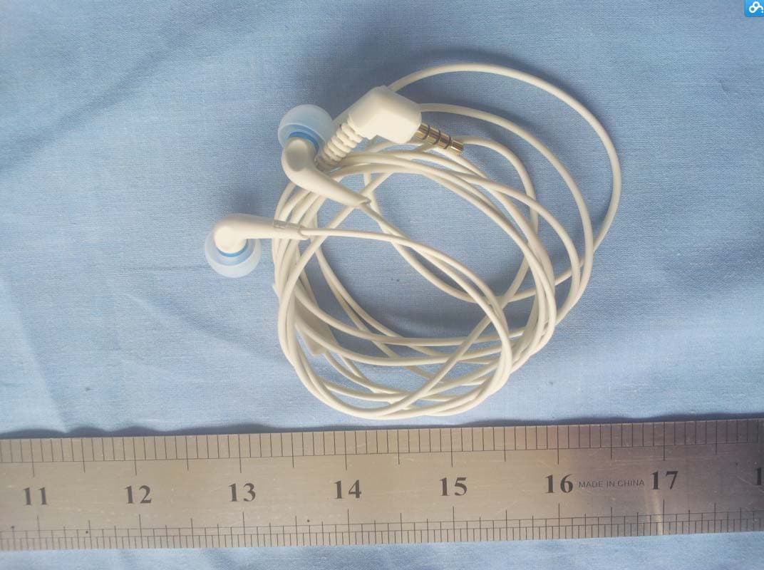
Click to zoom
Application Details
- Equipment Class
- PCT - PCS Licensed Transmitter worn on body
- Date of Grant
- Jun 30, 2014
- Application Purpose
- Original Equipment
- Date of Application
- Jun 21, 2014
- Equipment Note
- Neptune pine
- Frequency Range
- 1712.40000000 - 1752.60000000
- Company
- Neptune Computer Inc.
- Country
- Canada
Documents & Files
Document Text
Text extracted from the exhibit documents filed with the FCC. Open a document above to read the original.
Users Manual
Neptune pine User Manual FCC ID: 2ABWUP312 February, 2014 Copyright © Neptune Computer Inc. All rights reserved. 1 1.Neptune pine Introduction 1.1 Neptune pine layout Neptune pine Front View Neptune pine Back View 2 Neptune pine Side View 1.2 Status icon and indicator Status icon and indicator at the top of the screen status bar can display status information and notifications. 3 Note Taken the device software upgrade continuously, state indicator may not consistent with the device show, please refer to our actual. 2.Get Started 2.1 Charge the battery Two way can be used to charge for Neptune pine : 1.Charge by charger for Neptune pine 2.Connected to PC by USB cable , charge Neptune pine. When the battery is low, Neptune pine display warning information;At low power, Neptune pine will automatically power off. 2.2 Power on/Off Before charging for Neptune pine,make sure SIM card and full charged battery installed. 1,Power On:Hold the power key until the boot screen appears to power on the phone. When the leading bar is finished,the phone will enter the Android operating system.Please keep waiting before the device initialize is completed. 2.Power Off:Hold the power key until shutdown options pop-up,choose shutdown to close device. 2.3 Lock and unlock the screen 2.3.1 Device lock Short press power key, locking device. If you do nothing on the device within the time by system default or pre-set lock screen time, the device will automatically lock. 2.3.2 Device unlock Short press power key, on the home screen with your fingers slide to unlock. 3.Basic Function 3.1 Main screen and main menu 4 3.2 Settings and program installation 3.2.1 Date and time Settings Date and time of Neptune pine can change as you need. 3.2.2 Language and input method 5 "Settings" - > select "Language & Input ", in the list, select wish to switch languages- > select the default in the list, select want to switch input method 3.2.3 Display Settings 6 Find the icon -> Settings - > Display- > show- > brightness/wallpaper/automatic rotary screen/bright screen/dormancy 3.2.4 Security Settings Find the icon - > Security 7 3.2.5 Backup and Reset > Settings - > backup & reset - > restore factory Settings ★Note Following data will be erased: Account Data and Settings of system and applications Downloads Following data will be remained: Current system software and binding application files in the SD card, such as music or photos 3.2.6 Ring set 8 ->Sound:silent mode, vibration mode and normal mode - > set the volume and rings 3.2.7 Applications management Users can be set into the open management application menu, enter the application management interface, you can view files downloaded, the application running state of options in the SD card, you can click on the program, open the application information interface, forced to stop the software and uninstall and stop using the corresponding operation. 9 Settings - > applications - > applications management 3.3 Phone functions 3.3.1 Dial - > input number, dial 10 -> Incoming call - > It is on the phone 3.3.2 Contacts -> Contacts 11 -> New contact 3.3.3 SMS and MMS - > new text messages (SMS) - > click on - > the contact search interface, select the contacts and add it to the addressee, please use commas between multiple contacts. 12 3.3.4 Email E-mail can send or receive information. N★otes Before create the account in the Neptune pine , you must set the email account on the computer.QQ mailbox, for example,click the setting on the top right corner of mailbox,entering into account options , check and save server option and collect mail option to finish email accounts server setup. > Create email accounts Find the icon: - > email 1. Enter email address and password, click next, began to connect email account; 2. Set the email check frequency, then enter into the next step; 3. Set up account name , click next, entering into email checking interface. Delete account 1. On the email interface, press menu key to open the menu, click Settings; 2. Click to delete email account, open the Settings interface; 3. Find the delete account options, click delete account, E-mail account will be deleted from the Neptune pine. 3.4 Network and Connection synchronization 3.4.1 3G data connection On the home page interface ,click > Settings > wireless and network interface. Click on the mobile network, enter the mobile network Settings. Enable mobile data checked can begin to connect the login.After the success of the login, mobile 13 phone status bar that there will be a 3 g network connection icon ( ), then you can on the normal use of mobile phones and the Internet related applications. Data roaming checked later, when the phone is in a state of roaming can also on the normal use of mobile phones and the Internet related applications. Access point name : WAP,NET and other Internet connection can be set and switch, additionally APN can be created through menu key. Network operators: web search and automatically selective network can be operated. 3.4.2 WiFi network connection Find the icon: - > Settings - > wireless and network - > wi-fi 14 -> Find wifi -> select wifi hotspot, enter wifi password -> wifi connection success 3.4.3 Bluetooth Turn on the Bluetooth function in the device, establish a wireless connection and exchange information with other Bluetooth compatible devices (such as computers, cell phones). Without solid obstacles ,Bluetooth connection will be better. Find the icon: -> Settings -> Wireless & networks -> Bluetooth 15 -> Select Bluetooth -> Find suitable Bluetooth devices -> Bluetooth pairing Note ★ Make sure the device that will connect with Neptune pine Bluetooth function activated and Bluetooth visibility turned on. During the connection process, set the pairing PIN code, the machine does not support the connection without a password. 3.4.4 GPS Neptune pine,equipped with high-performance navigation chip, can quickly obtain accurate positioning information,download the…
Text truncated - open the document above for the full version.
Cover Letter(s)
Neptune Computer Inc. Cover letter Date:2014‐03‐24 FCC ID: 2ABWUP312 To whom it may concern, The devise is operating in the 2412‐2462MHz band. Any devise with the FCC ID: 2ABWUP312 on it cannot transmit above 2462MHz. Thank you
External Photos
2ABWUP312 External Photo
ID Label/Location Info
2ABWUP312 Label and Label Location
Internal Photos
2ABWUP312 Internal Photo 2G/3G antenna BT/Wifi antenna
RF Exposure Info
Report No.: RXC1312-0222SAR02R2 Page 1 of 174 TESTING No. L2264 SAR TEST REPORT Product Name Neptune pine Model P312 FCC ID 2ABWUP312 Client NEPTUNE COMPUTER INC. Manufacturer NEPTUNE COMPUTER INC. Date of issue June 10, 2014 TA Technology (Shanghai) Co., Ltd. TA Technology (Shanghai) Co., Ltd. Test Report Report No.: RXC1312-0222SAR02R2 Page 2 of 174 GENERAL SUMMARY Reference Standard(s) FCC 47CFR §2.1093 Radiofrequency Radiation Exposure Evaluation: Portable Devices ANSI C95.1, 1992: Safety Levels with Respect to Human Exposure to Radio Frequency Electromagnetic Fields, 3 kHz to 300 GHz.(IEEE Std C95.1-1991) IEEE Std 1528™-2003: IEEE Recommended Practice for Determining the Peak Spatial-Average Specific Absorption Rate (SAR) in the Human Head from Wireless Communications Devices: Measurement Techniques. KDB 865664 D01 SAR measurement 100 MHz to 6 GHz v01r03: SAR Measurement Requirements for 100 MHz to 6 GHz KDB 447498 D01 Mobile Portable RF Exposure v05r02: Mobile and Portable Device RF Exposure Procedures and Equipment Authorization Policies KDB 648474 D04 Handset SAR v01r02: SAR Evaluation Considerations for Wireless Handsets. KDB 941225 D01 SAR test for 3G devices v02: SAR Measurement Procedures CDMA 20001x RTT, 1x Ev-Do, WCDMA, HSDPA/HSPA KDB 941225 D02 HSPA and 1x Advanced v02r02 SAR Guidance for HSPA, HSPA+, DC-HSDPA and 1x-Advanced KDB 941225 D03 Test Reduction GSM_GPRS_EDGE v01:Recommended SAR Test Reduction Procedures for GSM/GPRS/EDGE KDB 248227 D01 SAR meas for 802 11 a b g v01r02: SAR Measurement Procedures for 802.11a/b/g Transmitters. Conclusion This portable wireless equipment has been measured in all cases requested by the relevant standards. Test results in Chapter 7 of this test report are below limits specified in the relevant standards for the tested bands only. General Judgment: Pass Comment The test result only responds to the measured sample. Approved by Weizhong Yang Director Revised by Minbao Ling SAR Manager Performed by Yi Zhang SAR Engineer TA Technology (Shanghai) Co., Ltd. Test Report Report No.: RXC1312-0222SAR02R2 Page 3 of 174 TABLE OF CONTENT 1. General Information ..................................................................................................................... 5 1.1. Notes of the Test Report ....................................................................................................... 5 1.2. Testing Laboratory ................................................................................................................ 5 1.3. Applicant Information ............................................................................................................ 6 1.4. Manufacturer Information ...................................................................................................... 6 1.5. Information of EUT ................................................................................................................ 7 1.6. EUT Antenna Locations ........................................................................................................ 9 1.7. The Maximum Reported SAR ............................................................................................. 10 1.8. Test Date ............................................................................................................................ 11 2. SAR Measurements System Configuration ................................................................................ 12 2.1. SAR Measurement Set-up .................................................................................................. 12 2.2. DASY5 E-field Probe System ............................................................................................. 13 2.2.1. EX3DV4 Probe Specification ....................................................................................... 13 2.2.2. E-field Probe Calibration .............................................................................................. 14 2.3. Other Test Equipment ......................................................................................................... 14 2.3.1. Device Holder for Transmitters .................................................................................... 14 2.3.2. Phantom ...................................................................................................................... 15 2.4. Scanning Procedure ........................................................................................................... 15 2.5. Dat a Storage and Evaluation .............................................................................................. 17 2.5.1. Data Storage ................................................................................................................ 17 2.5.2. Data Evaluation by SEMCAD ...................................................................................... 17 3. Laboratory Environment ............................................................................................................. 19 4. Tissue-equivalent Liquid ............................................................................................................ 20 4.1. Tissue-equivalent Liquid Ingredients ................................................................................... 20 4.2. Tissue-equivalent Liquid Properties .................................................................................... 22 5. System Check ............................................................................................................................ 23 5.1. Description of System Check .............................................................................................. 23 5.2. System Check Results ........................................................................................................ 25 6. Operational Conditions during Test ............................................................................................ 27 6.1. Ge…
Text truncated - open the document above for the full version.
RF Exposure Info
TA Technology (Shanghai) Co., Ltd. Test Report Report No.: RXC1312-0222SAR02R2 Page 91 of 174 Figure 21 Front Side, UMTS Band II Channel 9400 TA Technology (Shanghai) Co., Ltd. Test Report Report No.: RXC1312-0222SAR02R2 Page 92 of 174 UMTS Band II Back Side Low Date: 4/26/2014 Communication System: UID 0, WCDMA (0); Frequency: 1852.4 MHz;Duty Cycle: 1:1 Medium parameters used (interpolated): f = 1852.4 MHz; σ = 1.477 S/m; ε r = 53.168; ρ = 1000 kg/m 3 Ambient Temperature:22.3 °C Liquid Temperature: 21.5°C Phantom section: Flat Section DASY5 Configuration: Sensor-Surface: 4mm (Mechanical Surface Detection) Probe: EX3DV4 – SN3677; ConvF(7.63, 7.63, 7.63); Calibrated: 11/28/2013; Electronics: DAE4 Sn1317; Calibrated: 1/16/2014 Phantom: SAM 2; Type: SAM; Measurement SW: DASY52, Version 52.8 (7); SEMCAD X Version 14.6.10 (7164) Back Side Low/Area Scan (81x91x1): Interpolated grid: dx=1.000 mm, dy=1.000 mm Maximum value of SAR (interpolated) = 1.52 W/kg Back Side Low/Zoom Scan (7x7x7)/Cube 0: Measurement grid: dx=5mm, dy=5mm, dz=5mm Reference Value = 23.704 V/m; Power Drift = 0.18 dB Peak SAR (extrapolated) = 2.10 W/kg SAR(1 g) = 1.36 W/kg; SAR(10 g) = 0.834 W/kg Maximum value of SAR (measured) = 1.48 W/kg TA Technology (Shanghai) Co., Ltd. Test Report Report No.: RXC1312-0222SAR02R2 Page 93 of 174 Figure 22 Back Side, UMTS Band II Channel 9262 TA Technology (Shanghai) Co., Ltd. Test Report Report No.: RXC1312-0222SAR02R2 Page 94 of 174 UMTS Band II Bottom Edge Middle Date: 4/26/2014 Communication System: UID 0, WCDMA (0); Frequency: 1880 MHz;Duty Cycle: 1:1 Medium parameters used: f = 1880 MHz; σ = 1.504 S/m; ε r = 53.137; ρ = 1000 kg/m 3 Ambient Temperature:22.3 °C Liquid Temperature: 21.5°C Phantom section: Flat Section DASY5 Configuration: Sensor-Surface: 4mm (Mechanical Surface Detection) Probe: EX3DV4 – SN3677; ConvF(7.63, 7.63, 7.63); Calibrated: 11/28/2013; Electronics: DAE4 Sn1317; Calibrated: 1/16/2014 Phantom: SAM 2; Type: SAM; Measurement SW: DASY52, Version 52.8 (7); SEMCAD X Version 14.6.10 (7164) Bottom Edge Middle/Area Scan (31x91x1): Interpolated grid: dx=1.000 mm, dy=1.000 mm Maximum value of SAR (interpolated) = 5.65 W/kg Bottom Edge Middle/Zoom Scan (7x7x7)/Cube 0: Measurement grid: dx=5mm, dy=5mm, dz=5mm Reference Value = 39.396 V/m; Power Drift = -0.05 dB Peak SAR (extrapolated) = 10.6 W/kg SAR(1 g) = 4.41 W/kg; SAR(10 g) = 1.63 W/kg Maximum value of SAR (measured) = 5.60 W/kg TA Technology (Shanghai) Co., Ltd. Test Report Report No.: RXC1312-0222SAR02R2 Page 95 of 174 Figure 23 Bottom Edge, UMTS Band II Channel 9400 TA Technology (Shanghai) Co., Ltd. Test Report Report No.: RXC1312-0222SAR02R2 Page 96 of 174 UMTS Band IV Front Side Middle Date: 4/24/2014 Communication System: UID 0, WCDMA (0); Frequency: 1732.6 MHz;Duty Cycle: 1:1 Medium parameters used: f = 1733 MHz; σ = 1.306 S/m; ε r = 39.731; ρ = 1000 kg/m 3 Ambient Temperature:22.3 °C Liquid Temperature: 21.5°C Phantom section: Flat Section DASY5 Configuration: Sensor-Surface: 4mm (Mechanical Surface Detection) Probe: EX3DV4 – SN3677; ConvF(8.22, 8.22, 8.22); Calibrated: 11/28/2013; Electronics: DAE4 Sn1317; Calibrated: 1/16/2014 Phantom: SAM 2; Type: SAM; Measurement SW: DASY52, Version 52.8 (7); SEMCAD X Version 14.6.10 (7164) Front Side Middle/Area Scan (81x91x1): Interpolated grid: dx=1.000 mm, dy=1.000 mm Maximum value of SAR (interpolated) = 0.329 W/kg Front Side Middle/Zoom Scan (7x7x7)/Cube 0: Measurement grid: dx=5mm, dy=5mm, dz=5mm Reference Value = 13.865 V/m; Power Drift = 0.043 dB Peak SAR (extrapolated) = 0.453 W/kg SAR(1 g) = 0.306 W/kg; SAR(10 g) = 0.200 W/kg Maximum value of SAR (measured) = 0.328 W/kg TA Technology (Shanghai) Co., Ltd. Test Report Report No.: RXC1312-0222SAR02R2 Page 97 of 174 Figure 24 Front Side, UMTS Band IV Channel 1413 TA Technology (Shanghai) Co., Ltd. Test Report Report No.: RXC1312-0222SAR02R2 Page 98 of 174 UMTS Band IV Back Side Low Date: 4/27/2014 Communication System: UID 0, WCDMA (0); Frequency: 1712.4 MHz;Duty Cycle: 1:1 Medium parameters used (interpolated): f = 1712.4 MHz; σ = 1.469 S/m; ε r = 52.971; ρ = 1000 kg/m 3 Ambient Temperature:22.3 °C Liquid Temperature: 21.5°C Phantom section: Flat Section DASY5 Configuration: Sensor-Surface: 4mm (Mechanical Surface Detection) Probe: EX3DV4 – SN3677; ConvF(7.77, 7.77, 7.77); Calibrated: 11/28/2013; Electronics: DAE4 Sn1317; Calibrated: 1/16/2014 Phantom: SAM 2; Type: SAM; Measurement SW: DASY52, Version 52.8 (7); SEMCAD X Version 14.6.10 (7164) Back Side Low/Area Scan (81x91x1): Interpolated grid: dx=1.000 mm, dy=1.000 mm Maximum value of SAR (interpolated) = 1.47 W/kg Back Side Low/Zoom Scan (7x7x7)/Cube 0: Measurement grid: dx=5mm, dy=5mm, dz=5mm Reference Value = 26.707 V/m; Power Drift = 0.01 dB Peak SAR (extrapolated) = 2.11 W/kg SAR(1 g) = 1.25 W/kg; SAR(10 g) = 0.751 W/kg Maximum value of SAR (measured) = 1.35 W/kg TA Technology (Shanghai) Co., Ltd. Test Report Report No.: RXC1312-0222SAR02R2 Page 99 of 174 Figure 25 Back Side, UMTS Band IV Channel 1312 TA Technology (Shanghai) Co., Ltd. Test Report Report No.: RXC1312-0222SAR02R2 Page 100 of 174 UMTS Band IV Bottom Edge Middle Date: 4/27/2014 Communication System: UID 0, WCDMA (0); Frequency: 1732.6 MHz;Duty Cycle: 1:1 Medium parameters used: f = 1733 MHz; σ = 1.489 S/m; ε r = 52.919; ρ = 1000 kg/m 3 Ambient Temperature:22.3 °C Liquid Temperature: 21.5°C Phantom section: Flat Section DASY5 Configuration: Sensor-Surface: 4mm (Mechanical Surface Detection) Probe: EX3DV4 – SN3677; ConvF(7.77, 7.77, 7.77); Calibrated: 11/28/2013; Electronics: DAE4 Sn1317; Calibrated: 1/16/2014 Phantom: SAM 2; Type: SAM; Measurement SW: DASY52, Version 52.8 (7); SEMCAD X Version 14.6.10 (7164) Bottom Edge Middle/Area Scan (31x91x1): Interpolated grid: dx=1.000 mm, dy=1.000 mm Maximum value of SAR (interpolated) = 3.25 W/kg Bottom Edge Middle/Zoom Scan (7x7x7)/Cube 0: Measurement grid: dx=5mm, dy=5mm, dz=5mm Reference Value = 32.706 V/m; Power Drift = -0.09 dB Peak SAR (extrapolated) =…
Text truncated - open the document above for the full version.
Test Report
Report No.: RXC1312-0222RF01R2 Page 1of 54 TESTING No. L2264 Part 22 TEST REPORT Product Name Neptune pine FCC ID 2ABWUP312 Model P312 Client NEPTUNE COMPUTER INC. Manufacturer NEPTUNE COMPUTER INC. Date of issue June 10, 2014 TA Technology (Shanghai) Co., Ltd. TA Technology (Shanghai) Co., Ltd. Test Report Report No.: RXC1312-0222RF01R2 Page 2of 54 GENERAL SUMMARY Reference Standard(s) FCC CFR47 Part 2 (2012) Frequency Allocations And Radio Treaty Matters; General Rules And Regulations FCC CFR 47 Part 22H (2012) Public Mobile Services(850MHz) ANSI/TIA-603-C(2004) Land mobile FM or PM Communications Equipment Measurements and Performance Standards. KDB 971168 D01 Power Meas License Digital Systems v02r01 Measurement Guidance for Certification of Licensed Digital Transmitters Conclusion This portable wireless equipment has been measured in all cases requested by the relevant standards. Test results in Chapter 2 of this test report are below limits specified in the relevant standards. General Judgment: Pass Comment The test result only responds to the measured sample. Approved by Weizhong Yang Director Revised by Lingling Kang RF Manager Performed by Yiqi Chen RF Engineer TA Technology (Shanghai) Co., Ltd. Test Report Report No.: RXC1312-0222RF01R2 Page 3of 54 TABLE OF CONTENT 1. General Information ..................................................................................................................... 4 1.1. Notes of the test report ......................................................................................................... 4 1.2. Testing laboratory ................................................................................................................. 5 1.3. Applicant Information ............................................................................................................ 5 1.4. Manufacturer Information ...................................................................................................... 5 1.5. Information of EUT ................................................................................................................ 6 1.6. Test Date .............................................................................................................................. 7 2. Test Information ........................................................................................................................... 8 2.1. Summary of test results ........................................................................................................ 8 2.2. RF Power Output .................................................................................................................. 9 2.3. Effective Radiated Power .................................................................................................... 11 2.4. Occupied Bandwidth ........................................................................................................... 11 2.5. Band Edge Compliance ...................................................................................................... 26 2.6. Peak-to-Average Power Ratio (PAPR) ............................................................................... 35 2.7. Frequency Stability ........................................................................................................... .. 37 2.8. Spurious Emissions at Antenna Terminals ......................................................................... 40 2.9. Radiates Spurious Emission ............................................................................................... 47 3. Main Test Instruments ................................................................................................................ 49 ANNEX A: EUT Appearance and Test Setup ..................................................................................... 53 A.1 EUT Appearance ................................................................................................................ 53 A.2 Test Setup ........................................................................................................................... 54 TA Technology (Shanghai) Co., Ltd. Test Report Report No.: RXC1312-0222RF01R2 Page 4of 54 1. General Information 1.1. Notes of the test report TA Technology (Shanghai) Co., Ltd. has obtained the accreditation of China National Accreditation Service for Conformity Assessment (CNAS), and accreditation number: L2264. TA Technology (Shanghai) Co., Ltd. has been listed on the US Federal Communications Commission list of test facilities recognized to perform electromagnetic emissions measurements. The site recognition number is 428261. TA Technology (Shanghai) Co., Ltd. has been listed by industry Canada to perform electromagnetic emission measurement. The site recognition number is 8510A. TA Technology (Shanghai) Co., Ltd. guarantees the reliability of the data presented in this test report, which is the results of measurements and tests performed for the items under test on the date and under the conditions stated in this test report and is based on the knowledge and technical facilities available at TA Technology (Shanghai) Co., Ltd. at the time of execution of the test. TA Technology (Shanghai) Co., Ltd. is liable to the client for the maintenance by its personnel of the confidentiality of all information related to the items under test and the results of the test. The sample under test was selected by the Client. This report only refers to the item that has undergone the test. This report alone does not constitute or imply by its own an approval of the product by the certification Bodies or competent Authorities. This report cannot be used partially or in full for publicity and/or promotional purposes without previous written approval of TA Technology (Shanghai) Co., Ltd. and the Accreditation Bodies, if it applies. If the electronic report is inconsistent with the printed one, it should be subject to the latter. T…
Text truncated - open the document above for the full version.
Test Report
Report No.: RXC1312-0222RF02R2 Page 1of 63 TESTING No. L2264 Part 24 TEST REPORT Product Name Neptune pine FCC ID 2ABWUP312 Model P312 Client NEPTUNE COMPUTER INC. Manufacturer NEPTUNE COMPUTER INC. Date of issue June 10, 2014 TA Technology (Shanghai) Co., Ltd. TA Technology (Shanghai) Co., Ltd. Test Report Report No.: RXC1312-0222RF02R2 Page 2of 63 GENERAL SUMMARY Reference Standard(s) FCC CFR47 Part 2 (2012) Frequency Allocations And Radio Treaty Matters; General Rules And Regulations FCC CFR47 Part 24E (2012) Personal Communications Services ANSI/TIA-603-C(2004) Land mobile FM or PM Communications Equipment Measurements and Performance Standards. KDB 971168 D01 Power Meas License Digital Systems v02r01 Measurement Guidance for Certification of Licensed Digital Transmitters Conclusion This portable wireless equipment has been measured in all cases requested by the relevant standards. Test results in Chapter 2 of this test report are below limits specified in the relevant standards. General Judgment: Pass Comment The test result only responds to the measured sample. Approved by Weizhong Yang Director Revised by Lingling Kang RF Manager Performed by Yiqi Chen RF Engineer TA Technology (Shanghai) Co., Ltd. Test Report Report No.: RXC1312-0222RF02R2 Page 3of 63 TABLE OF CONTENT 1. General Information ..................................................................................................................... 4 1.1. Notes of the test report ......................................................................................................... 4 1.2. Testing laboratory ................................................................................................................. 5 1.3. Applicant Information ............................................................................................................ 5 1.4. Manufacturer Information ...................................................................................................... 5 1.5. Information of EUT ................................................................................................................ 6 1.6. Test Date .............................................................................................................................. 7 2. Test Information ........................................................................................................................... 8 2.1. Summary of test results ........................................................................................................ 8 2.2. RF Power Output .................................................................................................................. 9 2.3. Effective Isotropic Radiated Power ..................................................................................... 11 2.4. Occupied Bandwidth ........................................................................................................... 15 2.5. Band Edge Compliance ...................................................................................................... 27 2.6. Peak-to-Average Power Ratio (PAPR) ............................................................................... 36 2.7. Frequency Stability ........................................................................................................... .. 38 2.8. Spurious Emissions at Antenna Terminals ......................................................................... 41 2.9. Radiates Spurious Emission ............................................................................................... 54 3. Main Test Instruments ................................................................................................................ 61 ANNEX A: EUT Appearance and Test Setup ..................................................................................... 62 A.1 EUT Appearance ................................................................................................................ 62 A.2 Test Setup ........................................................................................................................... 63 TA Technology (Shanghai) Co., Ltd. Test Report Report No.: RXC1312-0222RF02R2 Page 4of 63 1. General Information 1.1. Notes of the test report TA Technology (Shanghai) Co., Ltd. has obtained the accreditation of China National Accreditation Service for Conformity Assessment (CNAS), and accreditation number: L2264. TA Technology (Shanghai) Co., Ltd. has been listed on the US Federal Communications Commission list of test facilities recognized to perform electromagnetic emissions measurements. The site recognition number is 428261. TA Technology (Shanghai) Co., Ltd. has been listed by industry Canada to perform electromagnetic emission measurement. The site recognition number is 8510A. TA Technology (Shanghai) Co., Ltd. guarantees the reliability of the data presented in this test report, which is the results of measurements and tests performed for the items under test on the date and under the conditions stated in this test report and is based on the knowledge and technical facilities available at TA Technology (Shanghai) Co., Ltd. at the time of execution of the test. TA Technology (Shanghai) Co., Ltd. is liable to the client for the maintenance by its personnel of the confidentiality of all information related to the items under test and the results of the test. The sample under test was selected by the Client. This report only refers to the item that has undergone the test. This report alone does not constitute or imply by its own an approval of the product by the certification Bodie…
Text truncated - open the document above for the full version.
Contact Information
Applicant
Aaron Wilkins(CTO)
Test Firm
TA Technology (Shanghai) Co., Ltd.Zhihui Liu
Technical Specifications
| # | Rule Parts | Frequency Range | Power Output | Emission | Tolerance |
|---|---|---|---|---|---|
| 7 | 27 | 1.71 GHz - 1.75 GHz | 92.00 mW | 4M19F9W | 0.003 ppm |