2ABXHVBCRX30VBar EVO
Mikado Model Helicopters GmbH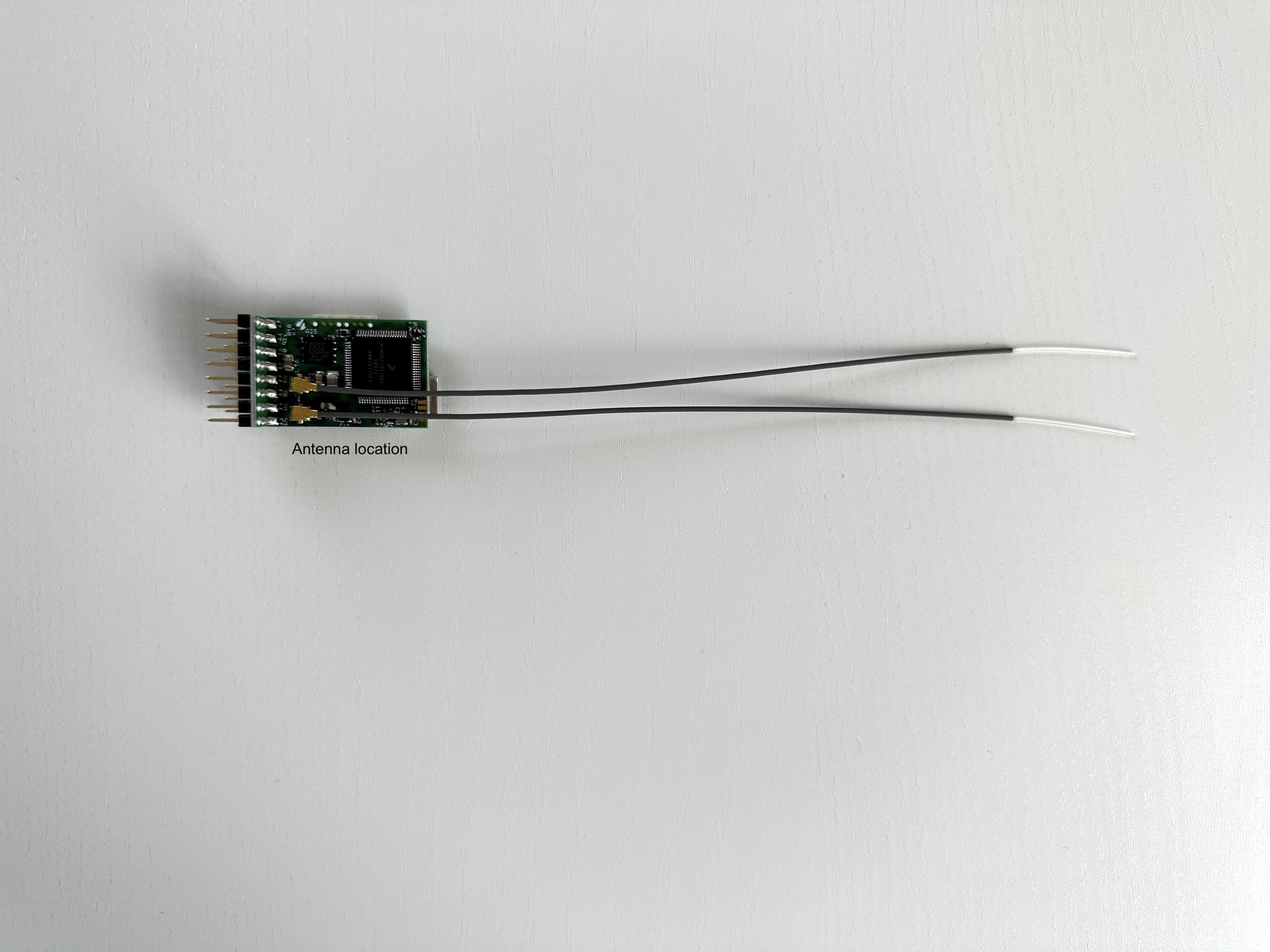
Click to zoom
Application Details
- Equipment Class
- DSS - Part 15 Spread Spectrum Transmitter
- Date of Grant
- Aug 27, 2023
- Application Purpose
- Original Equipment
- Date of Application
- Aug 27, 2023
- Equipment Note
- VBar EVO
- Frequency Range
- 2401.06400000 - 2480.71200000
- Country
- Germany
Documents & Files
Document Text
Text extracted from the exhibit documents filed with the FCC. Open a document above to read the original.
Users Manual
VBAR EVO Quick Start Guide Express-Firmware Welcome to VBar EVO! VBar EVO is an innovative product setting new standards for model helicopters in terms of flight performance and program- ming capacity. Features: • Easy setup and fine adjustments can be done with any VBar Control radio. • Ready for online updates as they become available. • Built-in Governor for electric model helicopters (IC powered models require the Pro firmware). • Fully compatible with VBar Control. For setup using VBar control, please refer to your VBar Control manual or to online help in VBar Con- trol EVO/Touch. FCC Statement This equipment has been tested and found to comply with the limits for a Class A digital de- vice, pursuant to part 15 of the FCC Rules. These limits are designed to provide reasonable protection against harmful interference when the equipment is operated in a commercial environment. This equipment generates, uses, and can radiate radio frequency energy and, if not installed and used in accordance with the instruction manual, may cause harmful interference to radio communications. Operation of this equipment in a residential area is likely to cause harmful interference, in which case the user will be required to correct the interference at his own expense. Changes or modifications not expressly approved by the party responsible for compliance could void the user’s authority to operate the device. The antenna(s) used for this transmitter must be installed to provide a separation distance of at least 20 cm / 7.87 in from all persons and must not be co-located or operating in conjunction with any other antenna or transmitter. End-users must be provided with transmitter operating conditions for satisfying RF exposure compliance. This device complies with part 15 of the FCC Rules. Operation is subject to the following two conditions: (1) This device may not cause harmful interference, and (2) this device must accept any interference received, including interference that may cause undesired operation. FCC ID 2ABXHVBCRX30 Safety Instructions An R/C controlled helicopter is not a toy! While moving, the rotor blades pose a serious danger to persons and things. You must obey all safety instructions of the manufacturer for operation of your helicopter. VBar is not an autopilot! VBar may be installed in model helicopters suitable for flying without flybar. During installation and operation you must follow all instructions given in the software of the radio and in manuals. VBar may not be operated in wet conditions (high humidity or rain). If the helicopter shows vibrations during flight, operation is to be stopped immediately. Do not continue flying until the cause for vibration has been eliminated. • Disconnect motor wires or remove the pinion gear to avoid acci- dental spooling up of the helicopter while setting up the speed con- troller (ESC), or when loading unknown setup, as they may contain different speed controller settings as you have on your heli! • Make sure you use a sufficient power supply. • Fail safe will be set automatically by VBar/VBar Control (motor off, servos on hold position). VBar EVO and high servo frequencies Your VBar NEO can—with update to Pro or Pro+Rescue— drive suitable servos with higher frequencies than before. Similar to overall gyro gain (too high = oscillation, wobbles, shaking), a wrong setting can degrade the flight performance, or even endanger/destroy the model. Please make sure you read the following tutorial before changing the default settings! https://www.vstabi.info/node/2455 1. Items needed for first installation On first installation, you will need: • VBar EVO with built in VBar Control VLink Receiver and a VBar Control radio • Power supply (BEC or receiver battery). • Helicopter with servos installed, but not yet connected! Only digital servos allowed! • Pitch Gauge (swash plate levelling tool) • For updates and extensions of VBar EVO you need the VBar Control Manager software which you can download conveniently from www.vstabi. info. Contents VBar EVO with built-in VBar Control Receiver, USB C wire, Gyro Pad. 2. Update and Registration Before beginning a setup, register and update your VBar Con- trol and VBar EVO. Open the VBar Control Manager, connect to your computer using the USB C wire, only then power up your VBar. The LED will flash white. The update will be performed automatically if necessary. During the update, the LED will light up yellow briefly, then start flashing green. Disconnect the USB wire and power cycle your VBar, and it will start up for normal operation, flashing blue during initialization, then red-green. If you want to use the VBar Control Manager again (e.g. to access the App Store), just power cycle your VBar. It will start up in update mode again as long as it is connected to your computer. Click on Applications in the VBar Control Manager to access the App Store, where you can register your new VBar to your MikadoID with one click of your mouse. Perform an update of your VBar Control, too. 3. Preparing the Helicopter First you need to assemble the helicopter in accordance with manufacturer’s instructions. Flybarred rotor systems are not supported. It is very important that you assemble the helicopter mechanically correct with exact symmetry and geometry. This is to ensure that you do not run into problems resulting from mechanical inconsistencies later. 4. Bind procedure, programming VBar will go into bind mode after approx. 10 seconds. The LED will flash green-red to indicate it‘s ready for binding. Refer to your VBar Control Manual to bind your VBar to your VBar Control Transmitter. 5. Wiring your VBar Connectors ESCElectronic Speed Controller TAILTail servo CH1-4Swash plate servos according to diagram in the software AUX1-3Additional functions RPMRPM sensor input USBUSB wire TELE 1, TELE 2Telemetry bus for VBar Control. Power supply may be connected to any port. There is no voltage divider needed for rpm sensors. Make sure all…
Text truncated - open the document above for the full version.
Attestation Statements
Mikado Model Helicopters GmbH • Graf-von-Schwerin-Str. 40 • 14469 Potsdam Bankverbindungen: Deutsche Bank Potsdam • BIC/Swift-Code: DEUTDEDB160 IBAN-Code: DE90 1207 0024 0322 9077 00 Commerzbank • BIC/Swift-Code: COBADEFFXXX IBAN-Code: DE19 1604 0000 0110 3399 00 Berliner Sparkasse • BIC/Swift-Code: BELADEBEXXX IBAN-Code: DE37 1005 0000 2060 0030 35 Kontakt: Tel. +49 (0)331 23749-0 Fax +49 (0)331 23749-11 [email protected] www.mikado-heli.de Graf-von-Schwerin-Str. 40 D – 14469 Potsdam Geschäftsführer: Ralf Buxnowitz USt.-Id. DE268655642 Steuer.-Nr. 046/114/05435 WEEE Reg.-Nr.: DE 51185953 Amtsgericht Potsdam HRB 22992 P TO: Federal Communications Commission Authorization and Evaluation Division 7435 Oakland Mills Road Columbia, MD 21046, USA Potsdam, 08. 08. 2023 RE: Attestation Statements Part 2.911(d)(7) request for (FCC ID 2ABXHVBCRX30) Mikado Model Helicopters GmbH, the undersigned, hereby authorize ABM Global LLC, DBA Mikado USA to act as our designated U.S. agent for service of process, Mikado Model Helicopters GmbH accepts to maintain an agent for no less than one year after the grantee has terminated all marketing and importation or the conclusion of any Commission-related proceeding involving the equipment. ABM Global LLC, DBA Mikado USA accepts the responsibility to act as designated U.S. agent for service of process, provides an agent for no less than one year after the grantee has terminated all marketing and importation or the conclusion of any Commission-related proceeding involving the equipment. Applicant Information: U.S. Agent Information: FRN 0034069781 Mikado Model Helicopters GmbH ABM Global LLC, DBA Mikado USA Graf-von-Schwerin-Str. 40 1000 Stinson Way Suite 104 14469 Potsdam West Palm Beach, FL, 33411 Germany USA Contact Name: Ralf Buxnowitz Contact Name: Bryan Barrow Telephone No: +49 331 23749 0 Telephone No: 001/5617013400 Email: [email protected] Email: [email protected] Applicant Signature: Agent Signature: Ralf Buxnowitz Bryan Barrow CEO CEO Mikado Model Helicopters GmbH ABM Global LLC, DBA Mikado USA
RF Exposure Info
HEADQUARTERS: 914 WEST PATAPSCO AVENUE • BALTIMORE, MARYLAND 21230 • PHONE (410) 354-3300 • FAX (410) 354-3313 Maryland | California | Texas www.metlabs.com DOC-EMC TEMP-6 (ETS330) 10/05/20 - Rev. 0- Approved by DOC Supervisor 4/25/2023 Mikado Model Helicopters GmbH (MIK3) Graf-von-Schwerin-Str. 40 Potsdam, 14469 Germany Dear Edward Eckstein, Enclosed is the EMC test report for testing of the Mikado Model Helicopters GmbH (MIK3), VBar EVO tested to the requirements of FCC Part 15.1091 and RSS-102 Issue 5 Thank you for using the services of Eurofins E&E North America. If you have any questions regarding these results or if MET can be of further service to you, please do feel free to contact me. Sincerely, Nancy LaBrecque Documentation Department Eurofins Electrical and Electronic Testing NA, Inc. Reference: WIRA125540_MPE Certificates and reports shall not be reproduced except in full, without the written permission of Eurofins E&E North America While use of the A2LA logo in this report reflects MET accreditation under these programs, the report must not be used by the client to claim product certification, approval, or endorsement by A2LA or any agency of the Federal Government. This letter of transmittal is not a part of the attached report. Eurofins MET Laboratories Inc. (Eurofins E&E North America) is part of the Eurofins Electrical & Electronics (E&E) global compliance network. Mikado Model Helicopters GmbH (MIK3) VBar EVO RF Exposure / MPE Report Report: WIRA125540_MPE © 2023, Eurofins E&E North America Page 3 of 14 DOC-EMC TEMP-6 (ETS330) 10/05/20 - Rev. 0 RF Exposure Criteria Test Report Using Maximum Permissible Exposure (MPE) Calculations for the Mikado Model Helicopters GmbH (MIK3) VBar EVO Tested under FCC Part 15.1091 and RSS-102 Issue 5 Report: WIRA125540_MPE 4/25/2023 Bryan Taylor, Wireless Team Lead Nancy LaBrecque Electromagnetic Compatibility Lab Documentation Department Engineering Statement: The measurements shown in this report were made in accordance with the procedures indicated, and the emissions from this equipment were found to be within the limits applicable. I assume full responsibility for the accuracy and completeness of these measurements, and for the qualifications of all persons taking them. It is further stated that upon the basis of the measurements made, the equipment tested is capable of operation in accordance with the requirements of the FCC Rules Part 15.247 under normal use and maintenance. Matthew Hinojosa EMC Manager, Austin Electromagnetic Compatibility Lab Mikado Model Helicopters GmbH (MIK3) VBar EVO RF Exposure / MPE Report Report: WIRA125540_MPE © 2023, Eurofins E&E North America Page 4 of 14 DOC-EMC TEMP-6 (ETS330) 10/05/20 - Rev. 0 Report Status Sheet Revision Report Date Reason for Revision 0 4/25/2023 Initial Issue. Mikado Model Helicopters GmbH (MIK3) VBar EVO RF Exposure / MPE Report Report: WIRA125540_MPE © 2023, Eurofins E&E North America Page 5 of 14 DOC-EMC TEMP-6 (ETS330) 10/05/20 - Rev. 0 Table of Contents 1.0 Requirements Summary ...................................................................................................................................... 8 2.0 Equipment Configuration ................................................................................................................................... 9 2.1 Overview.......................................................................................................................................................... 9 2.2 Test Site ......................................................................................................................................................... 10 2.3 References ...................................................................................................................................................... 10 2.4 Description of Test Sample ............................................................................................................................ 11 2.5 Modifications ................................................................................................................................................. 11 2.5.1 Modifications to EUT ................................................................................................................. 11 2.5.2 Modifications to Test Standard ................................................................................................... 11 2.6 Disposition of EUT ........................................................................................................................................ 11 3.0 Transmitter Requirements ................................................................................................................................ 12 Mikado Model Helicopters GmbH (MIK3) VBar EVO RF Exposure / MPE Report Report: WIRA125540_MPE © 2023, Eurofins E&E North America Page 6 of 14 DOC-EMC TEMP-6 (ETS330) 10/05/20 - Rev. 0 List of Tables Table 1. Summary of Test Results ............................................................................................................................... 8 Table 2. EUT Summary Table ...................................................................................................................................... 9 Table 3. References .................................................................................................................................................... 10 Table 4. Support Equipment ....................................................................................................................................... 11 Mikado Model Helicopters GmbH (MIK3) VBar EVO RF Exposure / MPE Report Report: WIRA125540_MPE © 2023, Eurofins E&E North America Page 7 of 14 DOC-EMC TEMP-6 (ETS330) 10/05/20 - Rev. 0 List of Terms and Abbreviations AC Alternating Current ACF Antenna Correction Factor Cal Calibration d Measurement Distance dB Decibels dBμA Decibels above one microa…
Text truncated - open the document above for the full version.
Test Report
HEADQUARTERS: 914 WEST PATAPSCO AVENUE • BALTIMORE, MARYLAND 21230 • PHONE (410) 354-3300 • FAX (410) 354-3313 The Nation’s First Licensed Nationally Recognized Testing Laboratory Maryland | California | Texas www.metlabs.com 6/12/2023 Mikado Model Helicopters GmbH (MIK3) Edward Eckstein Graf-von-Schwerin-Str. 40 Potsdam, 14469 Germany Dear Edward Eckstein, Enclosed is the EMC Wireless test report for compliance testing of the Mikado Model Helicopters GmbH (MIK3) VBar EVO as tested to the requirements of FCC Part 15.247, RSS-247 Issue 2 for Intentional Radiators. Thank you for using the services of Eurofins MET Labs. If you have any questions regarding these results or if MET can be of further service to you, please feel free to contact me. Sincerely yours, EUROFINS MET LABS Nancy LaBrecque Documentation Department Reference: WIRA125540_15.247_RSS247_R1 Certificates and reports shall not be reproduced except in full, without the written permission of Eurofins MET Labs. Mikado Model Helicopters GmbH (MIK3) Bluetooth FHSS Test Report VBar EVO FCC Part 15.247, RSS-247 Issue 2 Report: WIRA125540_15.247_RSS247_R1 © 2023, Eurofins MET Labs Page 2 of 52 Maryland | California | Texas www.metlabs.com FHSS Test Report for the Mikado Model Helicopters GmbH (MIK3) VBar EVO Tested under FCC Part 15.247, RSS-247 Issue 2 For Intentional Radiators Bryan Taylor, Wireless Team Lead Nancy LaBrecque Electromagnetic Compatibility Lab Documentation Department Engineering Statement: The measurements shown in this report were made in accordance with the procedures indicated, and the emissions from this equipment were found to be within the limits applicable. I assume full responsibility for the accuracy and completeness of these measurements, and for the qualifications of all persons taking them. It is further stated that upon the basis of the measurements made, the equipment tested is capable of operation in accordance with the requirements of the FCC Rules Part 15.247 under normal use and maintenance. Matthew Hinojosa EMC Manager, Austin Electromagnetic Compatibility Lab Mikado Model Helicopters GmbH (MIK3) Bluetooth FHSS Test Report VBar EVO FCC Part 15.247, RSS-247 Issue 2 Report: WIRA125540_15.247_RSS247_R1 © 2023, Eurofins MET Labs Page 3 of 52 Maryland | California | Texas www.metlabs.com Report Status Sheet Revision Report Date Reason for Revision 4/25/2023 Initial Issue. 1 6/12/2023 Implemented changes from TCB review Mikado Model Helicopters GmbH (MIK3) Bluetooth FHSS Test Report VBar EVO FCC Part 15.247, RSS-247 Issue 2 Report: WIRA125540_15.247_RSS247_R1 © 2023, Eurofins MET Labs Page 4 of 52 Maryland | California | Texas www.metlabs.com Table of Contents I. Executive Summary .................................................................................................................................................8 A. Purpose of Test ...................................................................................................................................................9 B. Executive Summary ............................................................................................................................................9 II. Equipment Configuration ..................................................................................................................................... 10 A. Overview ........................................................................................................................................................... 11 B. References ......................................................................................................................................................... 14 C. Test Site ............................................................................................................................................................ 15 D. Measurement Uncertainty ................................................................................................................................. 15 E. Description of Test Sample ............................................................................................................................... 15 F. Equipment Configuration .................................................................................................................................. 16 G. Support Equipment ........................................................................................................................................... 16 H. Ports and Cabling Information .......................................................................................................................... 16 I. Mode of Operation ............................................................................................................................................ 17 J. Method of Monitoring EUT Operation ............................................................................................................. 17 K. Modifications .................................................................................................................................................... 17 a) Modifications to EUT .................................................................................................................. 17 b) Modifications to Test Standard.................................................................................................... 17 L. Disposition of EUT ........................................................................................................................................... 17 III. Electromagnetic Compatibility Criteria for Intentional Radiators ................................................................... 18 § 15.203 Antenna Requirement ............................................................................................................................. 19 § 15.207(a) Conducted Emissions Limits .......................................................…
Text truncated - open the document above for the full version.
Test Report
EVO Wire Antenna ƛ/4 Dipole Frequency Range2400Mhz – 2500Mhz Antenna gain2dbi Max VSWR2.5:1 Max PolarizationLinear, vertical Impedance50 Ohm ConnectorU.Fl (IPEX) Cable180mm Length, 1.3mm Diameter, 28.5mm radiator stub MIKADO Model Helicopters GmbH Graf-von-Schwerin-Str. 40 DE 14469 Potsdam
Test Setup Photos
Photograph 1. Radiated Emissions, (30 MHz – 1000 MHz), Front View Photograph 2. Radiated Emissions, (30 MHz – 1000 MHz), Rear View Photograph 3. Radiated Emissions, (30 MHz – 1000 MHz), Antenna View Photograph 4. Radiated Emissions, (1 GHz – 18 GHz), Front View Photograph 5. Radiated Emissions, (1 GHz – 18 GHz), Rear View Photograph 6. Radiated Emissions, (1 GHz – 18 GHz), Antenna View
Contact Information
Applicant
Ralf Buxnowitz
Technical Contact
UR EngineeringUlrich Roehr
[email protected]49 6181 990 229
Theodor-Heuss-Str. 73 · Hanau, Hessen · Germany
Test Firm
EUROFINS ELECTRICAL AND ELECTRONIC TESTING NA, INCGreg Kovolenko
Technical Specifications
| # | Rule Parts | Frequency Range | Power Output |
|---|---|---|---|
| 1 | 15C | 2.40 GHz - 2.48 GHz | 47.00 mW |