2ABXZU-6298Wireless Microphone
ENPING SHENGYI ELECTRONIC CO., LTD.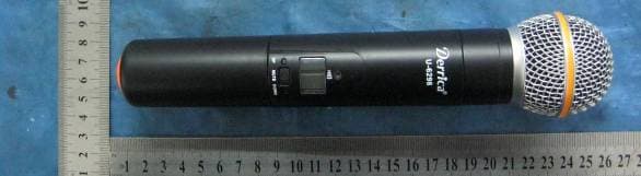
Click to zoom
Application Details
- Equipment Class
- TBF - Licensed Broadcast Transmitter Held to Face
- Date of Grant
- Mar 25, 2014
- Application Purpose
- Original Equipment
- Date of Application
- Mar 25, 2014
- Equipment Note
- Wireless Microphone
- Frequency Range
- 470.20000000 - 607.80000000
- Country
- China
Documents & Files
Document Text
Text extracted from the exhibit documents filed with the FCC. Open a document above to read the original.
Users Manual
User’s Manu for wireless microphone Dual Channels Single Channel When you want to set-up a new frequency, please do use the AUTO Searching function by pressing Set-Up key in 1 seconds of the receiver to search the best frequency around you, and then press the Set-Down key for 1 seconds and put the tr ansmitter IR close to the Receiver IR window, to match the receiver and transmitter in same frequency. Don’t just press the Set-UP or DOWN key to change a new frequen cy simply. ▲ 2*100 Channels ▲ 1*100 channels ▲ Auto channel searching , infrared channel matching ▲ microphone (transmitter) can be worked with anyone of this receiver Preview Welcome to choose this UHF wireless microphone system. This UHF wireless microphone system is professionally designed and manufactured with: ● Perfect sound quality ● The improved DPLL receiving mode with multi-channels ● UHF frequency, 2*100 channels to avoid interference. ● 100 frequencies in each Microphone make s more stable operating , more reliable transmitting. ● Auto-channel-searching and locking makes the operating easily. ● Infrared-channel-matching makes the operating of matching the receiver and transmitter in same frequency easily. Don’t operate the system under the followin g situation, for any repairing, only professional technicians ar e allowed to avoid danger. -- -1- -- Receiver Operatin g ------------ Receiver Front Panel Dual 6 5 4 3 2 2 1 Single Receiver Rear Panel Dual 6 7 8 9 10 8 7 6 Single ---2— 1. Power On/Off 2. Volume 3. Set-A and Set-B Searching Best Frequency: Press “SET-- ▲ ” key for 1 second to search the best operating channel (frequency) Auto Matching: Press “SET-- ▼ - ” key for 1 second, put the transmitter ASC aim to the receiver ASC window, transmit the channel index to transmitter, it may automatically matching the channel between receiver and transmitter. press “ ▲” or “▼”in 3 second to change the selected channel, press “SET - ▼”key for 1 second again to match the transmitter (we don’t pre fer to change the channel in this way) 4. ASC window 5. LCD display: Channel number, RF level, AF level, Mute, Frequency 6. Antenna 7. Audio balanced output 8. Squelch and noise mute adjusting button. Adjusting range is 0-40dB. 9. Audio Unbalanced output 10.Power Jack: connecting a 12v DC 50/60Hz adaptor for power. LCD of receiver Dual Single 1. 8-level RF display: to display the RF level 2. 8-level AF display: to display the AF level 3. Frequency display: when FREQ lighting, the last 6 figure means the working frequency. 4. Channel Display: when CHAN lighti ng, it display the working channel. 5. Channel or Frequency display. It shows the working channel or frequency. 6. MUTE display: MUTE lighting means the system hasn’t receive the RF signal. Receiver Operating 1. Turn Off the transmitter, Turn the Volume to “low”. 2. Turn on the receiver, check the RF and AF level, if interference too large, change the channel to avoid any interference . 3. Turn on the transmitter, the working RF-level displa y lighting, turn the volume to suitable level, then speak, the AF-level display working according to your voice. 4. Take off the power switch when finish using. --3-- Auto searching Channel1. Set-up the left Channel (Set.A) Press “SET-- ▲ ” key for 1 second, the display shows the sy stem is automatically searching the best workable frequency (channel). (Picture 1). Infrared matching channel Put the transmitter’s ASC sensor close to the receiver’s ASC sensor, press “SET-- ▼ ” key for 1 seconds, it will automatically transmit the chan nel index to the transmitter (microphone)----(Picture 2) After the 1 st and 2 nd steps fnished, the handheld microphone (transmitter) LED light,means working. Dual Single 2. Set-up the right channel (Set.B) Set-up the right channel (Set.B) in same steps. When the microphone and receiver shows same channels, the system is workable.(Pic. 3) Remarks: press “ ▲” or “▼” in 3 seconds to change the working channel. (we don’t prefer to change the channel in this way) - -4- Function of Handheld Transmitter(Microphone in Metal body) 1. Microphone head 2. ASC sensor 3. LCD display 4. Up/Down key, for changing channel or frequency 5. Handheld mic---Power ON/OFF switch—press it for 5 seconds Mute—Press it for 3 seconds Bodypack Transmitter: ON—MUTE--OFF 6. Battery case: 2pcs of 1.5v AA batteries. 7. Gain 8. Microphone Input Jack --5-- LCD display of transmitter (Microphone) 1. Frequency : indicate the working frequency 2. Channel: indicate the working channel 3. Low battery display: i ndicate the battery state. Operating of the handheld transmitter (Microphone) 1. Turn on the transmitter, the LCD display will show the frequency, channel, battery state. 2. If the display show different frequency (chann el) with receiver, take the microphone “ASC sensor” close to the receiver “ASC” window, press the receiver “SET-- ▼ ” key for 1 second, check again the receiver and microphone are in same frequency (channel), the RF light on the front panel of receiver lights, then the system is workable. BATTERY 1. Screw out the battery case cover, push it out. 2. Put in 2 new 1.5v AA (NO.5) batteries, please make sure the bat teries in right direction. 3. Push the cover in and make it tighten. Take off the batteries if not using fo r long time, the waist batteries must be take to Recycling Box . --6-- Technical Index System Carrier Frequency Range: 470-608MHz Mode: FM (wide band) Channels: 100 channels * 2 Channel distance: 1MHz Stability: +/- 0.005% Dynamic Range: 100dB Max deviation: +/-45KHz with level limiting Frequency Response: 60Hz-18KHz (+/-3dB) S/N ratio: >98dB T.H.D.: <0.5% Operating Range: 80m (under typical conditions) Ambient Temperature: -10°C~+50°C Receiver Receiving Mode: DPLL M Frequency: 110MHz, 10.7MHZ Antenna input: BNC/50Ω Sensitivity: 7dBuV (90dB S/N) Sensitivity Adjusting Range: 12-32dBuV Noise Rejection: >75dB Max output Level: +400mVp Transmitter(microphone) Antenna: Built-in RF Output: mW Noise Rejection: -60dB Powe…
Text truncated - open the document above for the full version.
Cover Letter(s)
Enping Shengyi Electronic Co., Ltd. Fl. 2-5, Shi Zi Shi Bldg., Xinping Rd., North, Enping, Gaungdong, China Tel: 86-0750-7122687 Equipment Autorisation Division Federal Communications Commission 7435 Oakland Mills Road Columbia, MD 21046 FCC ID: 2ABXZU-6298 Product Name: VHF Wireless Microphone Request for Confidentiality Pursuant to Sections 0.457 and 0.459 of the commissions rules, we hereby request that the following documents be held confidential: • Schematics • Block diagram • Operational Description • Parts List • Tune up Procedure These materials contain trade secrets and proprietary information and are not customarily released to the public. The public disclosure of this information might be harmful to the company and provide unjustified benefits to our competitors. Dated this 07 Day of Mar 20 14 By: Signature Printed Title: Manager On behalf of : Enping Shengyi Electronic Co., Ltd Telephone: 86-0750-7122687
Cover Letter(s)
Enping Shengyi Electronic Co., Ltd. Fl. 2-5, Shi Zi Shi Bldg., Xinping Rd., North, Enping, Gaungdong, China Tel: 86-0750-7122687 Aug-31-2012 Nemko Canada Inc 303 River Road Ottawa, Ontario, Canada K1V 1H2 Attn: Director of Certification Authority to Act as Agent On our behalf, I appoint Guangzhou Huesent Testing Service Co., Ltd._ NO.91 Dongguanzhuang Road Tianhe district, Guangzhou,Guangdong,China. Sandy__(Name and address,person). to act as our agent in the preparation of this application for equipment certification. I certify that submitted documents properly describe the device or system for which equipment certification is sought. I also certify that each unit manufactured, imported or marketed, as defined in the Federal Communications Commission’s regulations will have affixed to it a label identical to that submitted for approval with this application. For instances where our authorized agent signs the application for certification on our behalf, I acknowledge that all responsibility for complying with the terms and conditions for certification, as specified by Nemko Canada Inc, still resides with Enping Shengyi Electronic Co., Ltd ( applicant name and address). Fl. 2-5, Shi Zi Shi Bldg., Xinping Rd., North, Enping, Gaungdong, China Dated this Mar 07 20 14 Agency agreement expiration date: By: Signature Printed Title: On behalf of : Telephone: 86-0750-7122687
Cover Letter(s)
Enping Shengyi Electronic Co., Ltd. Fl. 2-5, Shi Zi Shi Bldg., Xinping Rd., North, Enping, Gaungdong, China Tel: 86-0750-7122687 Model Specification We, the undersigned, hereby declare that the following radio equipment Wireless Microphone Model: U-6298, U-6198, U-6988, U-6198, U-1100, U-2100, U-2018, U-2008, U-2400, U-2788, U-2988, U-3988, U-5988, Derrica-509, Derrica-508, Derrica-1000, Derrica-2002, TWM-321, TWM-322, TWM- xxx, PGX24, MGX24, BGX24, UHXPRO-01, UHXPRO-02, UPRO-M, UPRO-H, UPRO-MM, UPRO- MH, JAGUAR, T-40, T-42, U-xxxx, PRO-xxxx are identified (included circuit diagram, PCB layout & components used without any modification) except the model name and appearance. − Point of contact: TEL: 86-0750-7122687 (Name, telephone and fax number) Fl. 2-5, Shi Zi Shi Bldg., Xinping Rd., North, Enping, Gaungdong, China (Place, date of issue) (Signature / stamp) Enping Shengyi Electronic Co., Ltd (Name and title in block letters)
External Photos
U-6298
ID Label/Location Info
FCC ID Label Sample FCC ID : 2ABXZU-6298 This device complies with part 74 of the FCC Rules
ID Label/Location Info
LABEL LOCATION:U-6298
Test Report
FCCID: 2ABXZU-6298 Report Number: HST201402-0291-FCC Page 1 of 25 Test Report Applicant: Enping Shengyi Electronic Co., Ltd. Address of Applicant: Fl. 2-5, Shi Zi Shi Bldg., Xinping Rd., North, Enping, Guangdong, China Equipment Under Test (EUT): EUT Name: Wireless Microphone Model No.: Listed on the 3 rd page Trade Mark: N/A Serial No.: Not supplied by client Standards: FCC PART 74H:2010 Date of Receipt: Feb. 10, 2014 Date of Test: Feb. 10 to Feb. 28, 2014 Date of Issue: Mar. 5, 2014 Test Result : PASS* z In the configuration tested, the EUT complied with the standards specified above. Tested by: Sandy Yu / EMC Engineer Authorized Signature: Henly Xie / Manager, Representative of the Lab This report refers to the General Conditions for Inspection and Testing Services, printed overleaf This report details the results of the testing carried out on one sample. The results contained in this test report do not relate to other samples of the same product. The manufacturer should ensure that all products in series production are in conformity with the product sample detailed in this report. This report may only be reproduced and distributed in full. If the product in this report is used in any configuration other than that detailed in the report, the manufacturer must ensure the new system complies with all relevant standards. The report must not be used by the client to claim product certification, approval, or endorsement by NVLAP, NIST, or any agency of the federal government. All test results in this report can be traceable to National or International Standards. The test report prepare by: Guangdong Huesent Testing & Inspection Technology Co., Ltd. No.91, Dongguanzhuang Road, Tianhe District, Guangzhou, China. Tel: 86-20-28263298 Fax: 86-20-28263237 http://www.hst.org.cn E-mail: [email protected] REPORT No: HST201402-0291-FCC Page 2 of 25 Contents 1 TEST SUMMARY ................................................................................................ 3 2 GENERAL INFORMATION .................................................................................. 4 2.1 Client Information........................................................................................................... 4 2.2 General Description of E.U.T.......................................................................................... 4 2.3 Details of E.U.T. ............................................................................................................. 4 2.4 Description of Support Units .......................................................................................... 4 2.5 Standards Applicable for Testing .................................................................................... 4 2.6 Test Location.................................................................................................................. 5 2.7 Deviation from Standards............................................................................................... 5 2.8 Abnormalities from Standard Conditions ........................................................................ 5 3 EQUIPMENTS USED DURING TEST ................................................................. 6 4 TEST RESULTS .................................................................................................. 7 4.1 E.U.T. Operation Condition ............................................................................................ 7 4.2 Test Procedure & Measurement Data ............................................................................ 8 4.2.1 Carrier Radiated Power & Radiated Spurious Emissions.................................. 8 4.2.2 Occupied Bandwidth ....................................................................................... 12 4.2.3 Frequency Stability.......................................................................................... 15 4.2.4 Modulation Characteristics.............................................................................. 17 4.2.5 EUT Constructional Details ............................................................................. 20 4.2.6 Antenna Photo ................................................................................................ 25 REPORT No: HST201402-0291-FCC Page 3 of 25 1 Test Summary Test Test Requirement Standard Paragraph Result Carrier Radiated Power FCC Part 2.1046 74.861 e) 1) 54–72, 76–88 & 174–216 MHz bands, 50 mW 470–608 and 614–806 MHz bands, 250 mW PASS Modulation Deviation FCC Part 2.1047 74.861 e) 3) Within 75kHz PASS Frequency Stability FCC Part 2.1055 74.861 e) 4) <0.005% 50 ppm PASS Operating Bandwidth FCC Part 2.1049 c) 74.861 e) 5) Within 200kHz PASS Unwanted Radiation FCC Part 2.1049 c) 74.861 e) 6) within the mask PASS Radiated Spurious Emission FCC Part 2.1053 74.861 d) 3) < 43+10lgP(W) dB PASS Remark: ♣The EUT has one channel, which is located in the range 470.200 MHz to 607.800MHz . Only test result of sample of Wireless Microphone in channels 470.2 MHz, 505.0 MHz and 607.8 MHz were recorded in this report. Model: U-6298, U-6198, U-6988, U-6198, U-1100, U-2100, U-2018, U-2008, U-2400, U-2788, U-2988, U-3988, U-5988, Derrica-509, Derrica-508, Derrica-1000, Derrica-2002, TWM-321, TWM-322, TWM-xxx, PGX24, MGX24, BGX24, UHXPRO-01, UHXPRO-02, UPRO-M, UPRO-H, UPRO-MM, UPRO-MH, JAGUAR, T-40, T-42, U-xxxx, PRO-xxxx Only tested U-6298, since the other models listed above are electric identical with only difference being the model name. REPORT No: HST201402-0291-FCC Page 4 of 25 2 General Information 2.1 Client Information Applicant: Enping Shengyi Electronic Co., Ltd. Address of Applicant: Fl. 2-5, Shi Zi Shi Bldg., Xinping Rd., North, Enping, Guangdong, China 2.2 General Description of E.U.T. EUT Name: Wireless Microphone Item No.: Listed on the 3 rd page Serial No.: Not supplied by client 2.3 Details of E.U.T. Power Supply: 3.0Vdc Battery ( 2*AA batteries ) Main Function: Wireless microphone system with an associated receiver f…
Text truncated - open the document above for the full version.
Contact Information
Applicant
YIN QIANG Chen
Test Firm
China CEPREI LaboratoryLihui Chen
Technical Specifications
| # | Rule Parts | Frequency Range | Power Output | Emission | Tolerance |
|---|---|---|---|---|---|
| 1 | 74.861 | 470.2 MHz - 607.8 MHz | 2.95 mW | 160KF3E | 36.0000000000 ppm |