2ABY4T500T500 FM Transmitter
Congress Network Corporation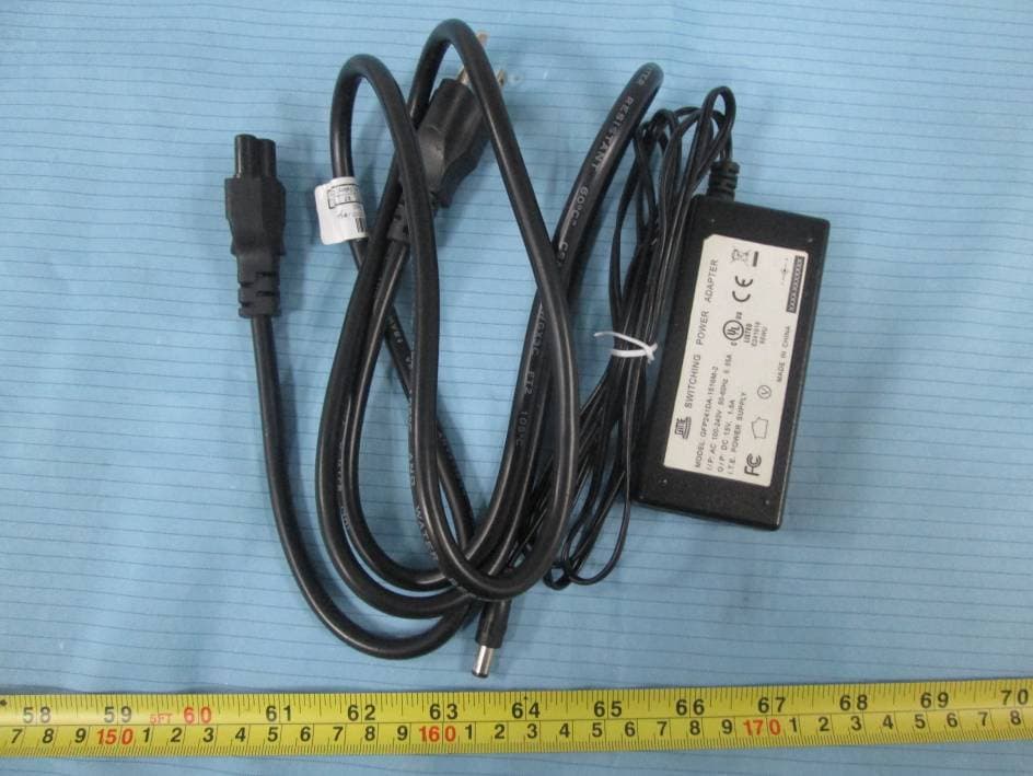
Click to zoom
Application Details
- Equipment Class
- GAT - Part 15 Auditory Assistance Device (Transmitter)
- Date of Grant
- Dec 30, 2014
- Application Purpose
- Original Equipment
- Date of Application
- Dec 30, 2014
- Equipment Note
- T500 FM Transmitter
- Frequency Range
- 75.30000000 - 75.90000000
- Company
- Congress Network Corporation
- Country
- United States
Documents & Files
Document Text
Text extracted from the exhibit documents filed with the FCC. Open a document above to read the original.
Users Manual
1 of 5 14/11/10 T-500 USER MANUAL 1. INTRODUCTION 1.1 Front panel 1.2 LCD screen Showing working channel (CH.01) or operating country mode RF signal strength indicator. Show Rx receiving signal --- N/A Appears when keypad is locked (10) DOWN AND KEY LOCK button (11) Headphones output jack (φ3.5mm) (12) Internal and external monitor switch (13) Internal monitor indicator (red light) (14) External monitor indicator (green light) (15) LCD screen (16) Input signal strength indicator: yellow light (17) Input signal strength indicator: green light (18) Input signal strength indicator: red light (1) POWER button (2) POWER indicator light (red light) (3) MUTE button (4) MUTE indicator light (red light) (5) MIC input jack (φ3.5mm) (6) Main Volume control (7) Headphones output gain control (8) UP button (9) MENU button 2 of 5 14/11/10 Middle TX power --- N/A High TX Power Low TX Power Appears when wide or narrow channel spacing Appears when Test Tone function is on Appears when the channel selected is in the scanning list --- N/A N/A N/A Battery level, showing the battery capacity (voltage) --- N/A 1.3 Rear panel Specifications: Dimensions(W*H*D):140mm*45 mm*116 mm; Weight: 1450g; 2.FUNCTION DESCRIPTION 2.1 POWER ON/OFF Pressing and holding [POWER] button for 2 seconds to turn on the radio, it will go to previous channel or initial channel [CH 01] (see Fig 1), pressing it for 2 seconds again will turn off the radio. Note: When the transmitter is turned on, the display will show full display during the start up. 3 of 5 14/11/10 2.2 CHANNEL SETTING Fig 1 Press the [UP] or [Down] button to choose the operating channel from channel 1 to 17. The TX power would be off during the switching interval. 2.3 Frequency SETTING Fig 2 In “frequency display” mode, the transmitter will show the frequencies instead of channel numbers (see Fig 2). Press [UP] or [Down] button to choose the operating frequency with default setting. Please note that if going in steps of 0.1Mhz there are only 17 frequencies available because some frequencies are restricted: Allowed frequencies are: 72.1, 72.2, 72.3, 72.4, 72.5, 72.6, 72.7, 72.8, 72.9, 74.7, 75.3, 75.4, 75.5, 75.6, 75.7, 75.8, 75.9 Mhz. 2.4 Channel / Frequency Lock Fig 3 Fig 4 By pressing and holding the UP or DOWN button for 5 seconds, the display will show “ “ icon (see Fig 3 & 4), the transmitter will be locked and the channel or frequency cannot be changed until the unit is unlocked by pressing and holding the [UP] or [DOWN] button for 5 seconds again. The lock option will remain even if the unit is turned off and on again or is unplugged from the power source. 3. Menu Options: Pressed and held the [MENU] button for 5 seconds, then the transmitter will enter into program mode, there are five items Test Tone, Tx Power, Display, Modulation, Exit in setting menu. After 10 seconds of inactivity the transmitter automatically will exit the program mode. 3.1 Test Tone Enter into program mode first option will blink “TONE”. 4 of 5 14/11/10 Fig 5 Fig 6 •Press the [UP] or [DOWN] button to select the [TONE.OFF] or [TONE. ON](see Fig 5 & 6). •Press [MENU] button to save the selected value and to go to the next menu option. 3.2 Tx Power Enter into program mode second option will blink [POWER] Fig 7 Fig 8 •Press the [UP] or [DOWN] button to select the [H] or [L] (see Fig 7 & 8). •Press [MENU] button to save the selected value and to go to the next menu option. 3.3 Display Mode Enter into program mode third option, the LCD will blink [DISPLAY]. Fig 9 Fig 10 •Press the [UP] or [DOWN] button can select [CHANNEL] or [FREQ] (see Fig 9 & 10). •Press [MENU] button to save the selected value and to go to the next menu option. 3.4 F Deviation Enter into program mode fourth option will blink “BAND-W” Fig 11 Fig 12 •Press the[ UP] or [DOWN] button to select the Band [W] or [N] (see Fig 11 & 12). •Press [MENU] button to save the setting and to go to the next menu option. 3.5 Exit Fig 13 Enter into program mode fifth option will blink [EXIT] •Press [MENU] button to exit the menu option. 5 of 5 14/11/10 4. RESET Press and hold down [UP] + [DOWN] buttons, then Power On the transmitter, it will go back to the initial channel [CH 01]. NOTE! This function is very useful if the transmitter is malfunctioning or if you want cancel all made settings. Reset shall restore the transmitter to default settings. FCC Caution: Any Changes or modifications not expressly approved by the party responsible for compliance could void the user's authority to operate the equipment. This device complies with part 15 of the FCC Rules. Operation is subject to the following two conditions: This device may not cause harmful interference, and (2) this device must accept any interference received, Including interference that may cause undesired operation. IC Warning This device complies with Industry Canada licence-exempt RSS standard(s). Operation is subject to the following two conditions: (1) this device may not cause interference, and (2) this device must accept any interference, including interference that may cause undesired operation of the device. Le présent appareil est conforme aux CNR d'Industrie Canada applicables aux appareils radio exempts de licence. L'exploitation est autorisée aux deux conditions suivantes : (1) l'appareil ne doit pas produire de brouillage, et (2) l'utilisateur de l'appareil doit accepter tout brouillage radioélectrique subi, même si le brouillage est susceptible d'en compromettre le fonctionnement This radio transmitter (identify the device by certification number, or model number if Category II) has been approved by Industry Canada to operate with the antenna types listed below with the maximum permissible gain and required antenna impedance for each antenna type indicated. Antenna types not included in this list, having a gain greater than the maximum gain indicated for that type, are strictly prohibited for use with this device. Le présent émetteur radio (identifier le dispositif par so…
Text truncated - open the document above for the full version.
Cover Letter(s)
IE I?] Congiess Network CoDohlion 7235 NW 19$ CT, Hollyvood. Florida31024. Uni&d Staros Tel: I-954-128-2roo Fax: l,lo5,?31-22?o QA-FR,I?O-B Signature: Eric Schur President FCC Confi dential Authorization 1v25/2014 FEDERAL COMMUNICATIONS COMMISSIONS Authorization and Evaluation Division 7435 Oakland Mills Road Columbia, MD 21046 Confidentiality Request regarding applicaiion forcertification ol FCC ID: 2ABY4T500 Pursuanl to Seclions 0.457 and 0.459 ofthe Commission's Rules, we hereby request confidential Ireatment ofinformation accompanying dris application as oullined below: . Block Diagram-- (Long term) . Circuit Description'-- (Long term) . Detailed Circuit Schematics ofEUT-- (Long term) The above materials conlain trade secrets and proprietary information not customarily released to the public. The public disclosure ofihese materials may be hannful to the applicant and provide unjustifled benefils to its competitofs. The applicant understands that pursuanl 10 Section 0.457 of the Rules, disclosufe ofthis application and all accompanying documentation will not be made before the date ofthe grant lor this application. Sincercly Yourg
External Photos
EXHIBIT B - EUT EXTERNAL PHOTOGRAPHS EUT – Front View EUT – Rear View EUT – Top View EUT – Bottom View EUT – Left View EUT – Right View Antenna Connecto r EUT – Adapter View EUT – Adapter Label View EUT – Antenna View
ID Label/Location Info
EXHIBIT A - FCC ID LABELING AND LOCATION FCC ID Label FCC ID Label Location The label shown shall be permanently affixed at a conspicuous location on the device and be readily visible to the user at the time purchase (Labeling requirements per 2.925)
Internal Photos
EXHIBIT C - EUT INTERNAL PHOTOGRAPHS EUT – Cover off View 1 EUT – Cover off View 2 EUT – Main Board 1 Top View EUT – Main Board 1 Bottom View EUT – Main Board 2 Top View EUT – Main Board 2 Bottom View
Test Report
Note: This test report is prepared for the customer shown above and for the equipment described herein. It may not be duplicated or used in part without prior written consent from Bay Area Compliance Laboratories Corp. FCC PART 15.237 TEST REPORT For Congress Network Corporation 7235 NW 19th CT, Hollywood, Florida 33024, United States FCC ID: 2ABY4T500 Report Type: Original Report Product Type: T500 FM Transmitter Test Engineer: Mike Hu Report Number: RSZ141113003-00 Report Date: 2014-12-04 Reviewed By: Jimmy Xiao RF En gineer Prepared By: Bay Area Compliance Laboratories Corp. (Shenzhen) 6/F, the 3rd Phase of WanLi Industrial Building, ShiHua Road, FuTian Free Trade Zone Shenzhen, Guangdong, China Tel: +86-755-33320018 Fax: +86-755-33320008 www.baclcorp.com.cn Bay Area Compliance Laboratories Corp. (Shenzhen) Report No.: RSZ141113003 -00 FCC Part 15.237 Page 2 of 19 TABLE OF CONTENTS GENERAL INFORMATION ....................................................................................................................................... 3 PRODUCT DESCRIPTION FOR EQUIPMENT UNDER TEST (EUT) ..................................................................................... 3 OBJECTIVE ................................................................................................................................................................... 3 RELATED SUBMITTAL(S)/GRANT(S) ............................................................................................................................. 3 TEST METHODOLOGY .................................................................................................................................................. 3 TEST FACILITY ............................................................................................................................................................. 4 SYSTEM TEST CONFIGURATION .......................................................................................................................... 5 JUSTIFICATION ............................................................................................................................................................. 5 EQUIPMENT MODIFICATIONS ....................................................................................................................................... 5 SUPPORT EQUIPMENT LIST AND DETAILS .................................................................................................................... 5 EXTERNAL I/O CABLE .................................................................................................................................................. 5 BLOCK DIAGRAM OF TEST SETUP ................................................................................................................................ 5 SUMMARY OF TEST RESULTS ............................................................................................................................... 6 FCC§15.203 - ANTENNA REQUIREMENT .............................................................................................................. 7 APPLICABLE STANDARD .............................................................................................................................................. 7 ANTENNA CONNECTOR CONSTRUCTION ...................................................................................................................... 7 FCC §15.207 – AC LINE CONDUCTED EMISSION ............................................................................................... 8 APPLICABLE STANDARD .............................................................................................................................................. 8 MEASUREMENT UNCERTAINTY .................................................................................................................................... 8 EUT SETUP .................................................................................................................................................................. 8 EMI TEST RECEIVER SETUP ......................................................................................................................................... 9 TEST EQUIPMENT LIST AND DETAILS ........................................................................................................................... 9 TEST PROCEDURE ........................................................................................................................................................ 9 CORRECTED FACTOR & MARGIN CALCULATION ......................................................................................................... 9 TEST RESULTS SUMMARY .......................................................................................................................................... 10 TEST DATA ................................................................................................................................................................ 10 §15.237(B) (C) FIELD STRENGTH .......................................................................................................................... 13 APPLICABLE STANDARD ............................................................................................................................................ 13 MEASUREMENT UNCERTAINTY .................................................................................................................................. 13 TEST EQUIPMENT SETUP ............................................................................................................................................ 13 EUT SETUP ................................................................................................................................................................ 14 TEST PROCEDURE .....................................................................................................…
Text truncated - open the document above for the full version.
Test Setup Photos
EXHIBIT D - TEST SETUP PHOTOGRAPHS Conducted Emissions – Front View Conducted Emissions – Side View Radiated Emissions
Contact Information
Applicant
Eric Schur(President)
Test Firm
Bay Area Compliance Laboratory Corp. (Shenzhen)John Chan
Technical Specifications
| # | Rule Parts | Frequency Range | Power Output |
|---|---|---|---|
| 3 | 15.237 | 75.3 MHz - 75.9 MHz | - |