2ABY4T500CLOUDT500 CLOUD FM Transmitter
Congress Network Corporation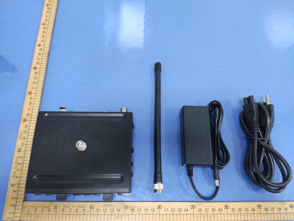
Click to zoom
Application Details
- Equipment Class
- GAT - Part 15 Auditory Assistance Device (Transmitter)
- Date of Grant
- Jan 08, 2026
- Application Purpose
- Original Equipment
- Equipment Note
- T500 CLOUD FM Transmitter
- Frequency Range
- 72.10000000 - 72.90000000
- Company
- Congress Network Corporation
- Country
- United States
Documents & Files
Document Text
Text extracted from the exhibit documents filed with the FCC. Open a document above to read the original.
Users Manual
1 USER MANUAL Passion for innovation Model T500-CLOUD Multi-Channel FM Transmitter 2 About this Manual Read this user manual carefully before installing and operating your T500 CLOUD FM Transmitter. Use the product only as described to avoid accidental injury, damage or hearing impairment. Also, read safety warnings carefully. Keep this manual for future reference. If you give this product to someone else, remember to include this manual. Package Contents (1) T500 CLOUD FM Transmitter (72-76 MHz) (1) Antenna (1) Power supply (1) User manual System Overview Thank you for choosing the Enersound T500 CLOUD FM Transmitter. This professional transmitter is designed for assistive listening and language interpretation. It wirelessly broadcasts a speaker’s voice, music or any audio signal up to 1000 ft. (305 m). The audience can use the optional R-120 FM multichannel receiver or any other compatible FM receiver operating on the 72-76 MHz frequency to pick up the broadcast. The T500 CLOUD FM Transmitter features 3 main audio inputs that allow the direct connection of virtually any analog audio source, including a 3.5 mm jack for headset microphones, an XLR & ¼ inch combination jack with a selector for dynamic microphones, condenser microphones or line-level signals, and a RCA line auxiliary input. It also has a recording output and a 3.5 mm monitor headphone jack. For language interpretation, it has a unique integrated interpreter monitor function. This feature allows interpreters to select an external incoming audio source and utilize a headset with microphone to listen to the source language without the need of an interpreter console or external headphone amplifier. Through the headphones’ volume control, interpreters can set the desired incoming audio level and the [MUTE] button allows them to momentarily silence their microphone for coughing or sneezing. For more advanced interpreting functions, it can also be utilized with the Enersound IC-12 multi-channel interpreter console or with any other interpretation platform with analog audio outputs. Its LCD display allows to easily program the various useful functions, such as test tone, RF power level, display mode (frequencies or channel numbers), and channel lock. 3 Quick Reference: Controls, Displays and Connectors Front panel (1) POWER button: Press & hold for 5 seconds to turn on/ off device. (2) Power indicator (3) Front microphone mute button: Press to mute/unmute front microphone. (4) Mute indicator light (5) Mic input, 3.5mm jack (6) Main volume control: Adjusts audio output volume. (7) Headphones volume control (8) Up button: Changes channel/frequency up. During setting mode, press to modify selection. (9) Menu button: Press & hold for 6 seconds to access setting menu. (10) Down & lock button: Changes channel/frequency down. Press & hold for 5 seconds to lock/ unlock channel/frequency. During setting mode, press to modify selection. (11) Headphones output, 3.5mm jack (12) Internal/external monitor source selection switch: Set to EXT for language interpretation applications to monitor an external audio source (speech to be translated). Set to INT to monitor the broadcasted audio. (13) Internal selection indicator (14) External selection indicator (15) LCD screen (16) (17) Audio level indicators (18) Audio peak indicator 4 Rear panel (19) Remote antenna connector Used when top mounted antenna is not convenient, for example when rack mounting. Use only ONE antenna connector at a time. (20) External monitor Input Used in language interpretation applications. The audio source to be translated should be connected here so the interpreter can listen to the source language. This signal will NOT be broadcasted to FM receivers. (21) Recording output This RCA jack contains a mix of Input 1, Input 2 and front 3.5 mm microphone. It can use for external signal out, the impedance is 10k ohm. (22) Input 2, RCA jack Connects unbalanced audio signals to be broadcasted. It can use for Aux input jack, the impedance is 10k ohm. (23) Gain Adjusts Input 1, Input 2 and front mic gain level. (24) Input 1 mode selector Selects line level, microphone level, or microphone with 12V phantom power for condenser mics. (25) Input 1 Accepts balanced or unbalanced connection of a microphone or line level input. This combination jack accepts either XLR or ¼” plugs. (26) Power supply jack Used with the included 15V power supply. (27) USB-C Connector-- This is used to connect the Laptop’s USB jack, it can use to read & record the music audio signal between T500-CLOUD & Laptop. 5 Set-up Instructions General Set-up Instructions: Unpack the transmitter Remove outer packaging and plastic cover. Inspect for physical damage and immediately report any issues. Position the unit Position the transmitter near the audio source (sound system, mixer, interpreter desk, etc.), away from metallic objects that might interfere with the antenna. Connect the antenna For tabletop use, screw in the antenna connector onto the transmitter top antenna connector. Alternatively, an optional remote antenna can be used. Do not use two antennas at the same time. Rack mount the unit (optional) The transmitter can be rack mounted, if necessary, in a 19’’ rack using the optional rack mount kits: single-unit RM-501 or double-unit RM-502. Dual rack mount RM-502 for 2 T500 CLOUD FM Transmitters NOTE: If rack mounting, do not use the top antenna connector; you will need to use the rear connection antenna with a 90 degree adapter AD-590 or use the optional rack-mount antenna kit RAK-500 available for purchase. If needed, you may also use a remote antenna. Only use original Enersound antennas. Check with your authorized Enersound dealer or visit www.enersound.com to view available accessories. • Power the Unit Plug the power supply into the power connector on the rear panel, then connect the power supply into an outlet. Only use the Enersound approved power supply. (The PS-500 is an auto switching power supply th…
Text truncated - open the document above for the full version.
Attestation Statements
Con gress Net*'ork Corporation ADD: 7235 NW l9th CT, Hollywood, Florida 33024, United States Tel: l-954-328-2100 Fa\: l-305-731-2270 Irmail: [email protected] Date:2025-12-2 FEDERAL COMMUNICATIONS COMMISSIONS Authorization and Evaluation Division 7435 Oakland Mills Road Columbia. MD 21046 Dear Sir/Madam, Our product T500 CLOUD FM Transmitter, model: T500-CLOUD, FCC ID: 2ABY4T500CLOUD, for marketing purpose, this product only supports FM (72-76MHz). The other functions and bands were disabled to use by manufacture in the software, the end user has no capability to activate it. Sincerely Yours, Signature:.ru_ Mr Eric Schur President
Attestation Statements
Congress Network Corporation ADD: 7235 NW l9th CT, Hollywood, Florida 33024, United States Tel: l-954-328-2100 Fax: l-305-731-2270 Email: [email protected] Attestation Letter Date:'2025-12-2 FEDERAL COMMT]NICATIONS COMMISSIONS Authorization and Evaluation Division 7435 Oakland Mills Road Columbia, MD 21046 Rel': Attestation Statements CFR 47 $2.91l(d)(5)(i) Filing FCC ID: 2ABY4T500CLOUD Congress Network Corporation certifies that the equipment for which authorization is sought is not "covered" equipment prohibited from receiving an equipment authorization pursuant to section 2.903 of the FCC rules. Sincerely Yours, Signature:& Mr Eric Schur President cFR 47 $2.91 l(dx5)(i) Anestation Letter
Attestation Statements
Congress Network Corporation ADD:7235 NW l9th CT, Hollywood, Florida 33024, United States Tel: l -954-328-2100 Fax: l-305-731-2210 Email: [email protected] Attestation Letter Date:2025-12-2 FEDERAL COMMUNICATIONS COMMISSIONS Authorization and Evaluation Division 7435 Oakland Mills Road Columbia, MD 21046 Ref: Attestation Statements CFR 47 $2.91 1(d)(5)(ii) Filing FCC ID:2ABY4T500CLOUD Congress Nefwork Corporation certifies that as ofthe date olthe filing ofthe application, the applicant !ry! identified on the Covered List as an entity producing "covered" equipment. And our product does not use Kaspersky software information. Sincerely Yours, Signarure: q^ f.4 Mr Eric Schur President cFR 47 $2.91 I (d)(sxii) Anestation Letter
Attestation Statements
U.S. AGENT LETTER OF ATTESTATION Date: 2025-12-2 FEDERAL COMMUNICATIONS COMMISSION Authorization and Evaluation Division 74 35 Oakland Mills Road Columbia, MD 21046 Ref: Attestation Statements CFR 47§2.91 l(d)(7) Filing FCC ID: 2ABY4T500CLOUD Congress Network Corporation ("the Applicant") certifies that, as of the date of the filing of the application, Congress Network Corporation (U.S. agent). is our designated U.S. a gent for service of process for the above referenced FCC ID. Congress Network Corporation ("the Applicant") accepts to maintain an agent for no less than one year after the grantee has terminated all marketing and importation or the conclusion of any Commission-related proceeding involving the equipment. Congress Network Corporation (U.S. agent) accepts, as of the date of the filing of the application, the obligation of the designated U.S. agent for service of process for the above referenced FCC ID. Designated U.S. Agent and Applicant Information: Name: Congress Network Corporation A ddress: 7235 NW 19th CT , Hollywood , Florida 33024 , United States FRN: 0023420433 Tel: 1-954-328-2100 三 : 三 了 三 言 chur `
Cover Letter(s)
Congress Network Corporation ADD: 7235 Nw l9th CT , Hollywood , Florida 33024 , United States Tel: l-954-328-2100 Fax: l-305-731-2270 Email: [email protected] FCC Authorization Date:2025-12-2 FEDERAL COMMLTNICATIONS COMMISSIONS Authorization and Evaluation Division 7435 Oakland Mills Road Columbia. MD 21046 Subject: Agent Authorization To whom it may concem: We Congress Network Corporation the undersigned, hereby authorizes Shenzhen Accurate Technology Co., Ltd. to act on its behalf in all matters relating to apptication lor Equipment authorization, including the signing of all documents relating to these matters. All acts carried out by Shenzhen Accurate Technology Co., Ltd. on our behalf shall have the same effect as our own action. We, the undersigned, hereby certifu that we are not subject to a denial offederal benefits, that includes FCC benefits, pursuant to Section 5301 ofthe Anti-Drug Abuse Act of 1988, 21 U.S.C. 862. This authorization is valid until further written notice from the applicant. Sincerely Yours, Signature: & Mr Eric Schur President QA-FR-170-B -:e 11 ;
Cover Letter(s)
Congress Network Corporation ADD: 7235 NW l9th CT, Hollywood, Florida 33024, United States Tel: l-954-328-2100 Fax:1-]05-'711-2210 Email : ericschur(@gmail.com FCC Confi dential Autho rization Date:2025-12-2 FEDERAL COMMUNICATIONS COMMISSIONS Authorization and Evaluation Division 7435 Oakland Mills Road Columbia, MD 21046 Subject: Confidentiality Request regarding application for certification of FCC ID:2ABY4T500CLOUD ln accordance with Sections 0.457 and 0.459 of the Commission's Rules, Congress Network Corporation hereby requests long-term confidential treatment of information accompanying this application as outlined below: o Block Diagram r Schematics o OperationDescription The above materials contain proprietary and confidential information not customarily released to the public. The public disclosure ofthese materials provides unjustified benefits to its competitors in the market. Sincerely Yours, Signature: Mr Eric Schur President
External Photos
Shenzhen Accurate Technology Co., Ltd. No.: 2504Y13176E-RF EUT External Photos External Photos Page 1 / 5 External Photos Shenzhen Accurate Technology Co., Ltd. No.: 2504Y13176E-RF EUT External Photos External Photos Page 2 / 5 Shenzhen Accurate Technology Co., Ltd. No.: 2504Y13176E-RF EUT External Photos External Photos Page 3 / 5 Shenzhen Accurate Technology Co., Ltd. No.: 2504Y13176E-RF EUT External Photos External Photos Page 4 / 5 Antenna Shenzhen Accurate Technology Co., Ltd. No.: 2504Y13176E-RF EUT External Photos External Photos Page 5 / 5 Adapter ***** END ***** ***** END *****
ID Label/Location Info
Label Location
Internal Photos
Shenzhen Accurate Technology Co., Ltd. No.: 2504Y13176E-RF EUT Internal Photos Internal Photos Page 1 / 7 Internal Photos Shenzhen Accurate Technology Co., Ltd. No.: 2504Y13176E-RF EUT Internal Photos Internal Photos Page 2 / 7 Shenzhen Accurate Technology Co., Ltd. No.: 2504Y13176E-RF EUT Internal Photos Internal Photos Page 3 / 7 Shenzhen Accurate Technology Co., Ltd. No.: 2504Y13176E-RF EUT Internal Photos Internal Photos Page 4 / 7 Shenzhen Accurate Technology Co., Ltd. No.: 2504Y13176E-RF EUT Internal Photos Internal Photos Page 5 / 7 Shenzhen Accurate Technology Co., Ltd. No.: 2504Y13176E-RF EUT Internal Photos Internal Photos Page 6 / 7 Shenzhen Accurate Technology Co., Ltd. No.: 2504Y13176E-RF EUT Internal Photos Internal Photos Page 7 / 7 ***** END *****
RF Exposure Info
Note: This report must not be used by the customer to claim product certification, approval, or endorsement by A2LA, or any agency of the Federal Government. The information marked “#” is provided by the applicant, the laboratory is not responsible for its authenticity and this information can affect the validity of the result in the test report. Customer model name, addresses, names, trademarks etc. are included but no need marked. This report cannot be reproduced except in full, without prior written approval of the Company. Unless otherwise stated the results shown in this test report refer only to the sample(s) tested. This report is valid only with a valid digital signature. The digital signature may be available only under the Adobe software above version 7.0. Shenzhen Accurate Technology Co., Ltd. Floor 1, KuMaKe Building, Dongzhou Community, Guangming Street, Guangming District, Shenzhen, Guangdong, China. Tel: +86 755-26503290 Web: www.atc-lab.com Rev:A/4.0(2024/11/01) Page 1 of 6 TR-4-E-R052 TEST REPORT Applicant Name : Congress Network Corporation Address : 7235 NW 19th CT, Hollywood, Florida 33024, United States Report Number : 2504Y13176E-RF-00B FCC ID: 2ABY4T500CLOUD Test Standard (s) FCC PART 2.1091 Sample Description Product Name: T500 CLOUD FM Transmitter Model No.: T500-CLOUD Trade Mark: Date Received: 2025-10-16 Report Date: 2025-12-01 Test Result: The EUT complied with the standards above. Prepared and Checked By: Approved By: Amanda Wei Bob.Liao EMC Engineer EMC Engineer Shenzhen Accurate Technology Co., Ltd. Report No.: 2504Y13176E-RF-00B Rev:A/4.0(2024/11/01) Page 2 of 6 TR-4-E-R052 TABLE OF CONTENTS DOCUMENT REVISION HISTORY ................................................................................................................ 3 GENERAL INFORMATION ............................................................................................................................ 4 PRODUCT DESCRIPTION FOR EQUIPMENT UNDER TEST (EUT) ........................................................................ 4 OBJECTIVE ................................................................................................................................................... 4 TEST FACILITY .............................................................................................................................................. 4 RF EXPOSURE .............................................................................................................................................. 5 APPLICABLE STANDARD ................................................................................................................................. 5 RESULT ........................................................................................................................................................ 5 EXHIBIT A-EUT PHOTOGRAPHS ................................................................................................................ 6 Shenzhen Accurate Technology Co., Ltd. Report No.: 2504Y13176E-RF-00B Rev:A/4.0(2024/11/01) Page 3 of 6 TR-4-E-R052 DOCUMENT REVISION HISTORY Revision Number Report Number Description of Revision Date of Revision Rev.00 2504Y13176E-RF-00B Original Report 2025-12-01 Shenzhen Accurate Technology Co., Ltd. Report No.: 2504Y13176E-RF-00B Rev:A/4.0(2024/11/01) Page 4 of 6 TR-4-E-R052 GENERAL INFORMATION Product Description for Equipment under Test (EUT) Product Name T500 CLOUD FM Transmitter Tested Model T500-CLOUD Voltage Range # DC 15.0V from Adapter Adapter Information # Model: WT24-1501000-T Input: 100-240V~ 50/60Hz 1.6A Output: 15.0V1.0A 15.0W Note: The EUT have two antenna connectors. One is top antenna connector for tabletop use; the other is remote antenna connector for rack mounting. Use only one antenna connector at a time. Frequency Range FM: 72-76MHz Maximum E-Field Strength (Peak) 97.76 dBuV/m@3m Antenna Specification # External Antenna, Antenna gain: 0dBi (It is provided by the applicant.) Sample Serial Number 3BD3-1 (Assigned by ATC, Shenzhen) Sample/EUT Status Good condition Objective This test report is in accordance with Part 2-Subpart J, Part 15-Subparts C and Part 2-Subpart J, Radiofrequency Radiation Exposure of the Federal Communication Commission rules. The tests were performed in order to determine compliance with FCC §2.1091 rules. Test Facility The test site used by Shenzhen Accurate Technology Co., Ltd. to collect test data is located on the Floor 1, KuMaKe Building, Dongzhou Community, Guangming Street, Guangming District, Shenzhen, Guangdong, China. Accredited by American Association for Laboratory Accreditation (A2LA).The Certificate Number is 4297.01. Shenzhen Accurate Technology Co., Ltd. Report No.: 2504Y13176E-RF-00B Rev:A/4.0(2024/11/01) Page 5 of 6 TR-4-E-R052 RF EXPOSURE Applicable Standard According to subpart 2.1091 systems operating under the provisions of this section shall be operated in a manner that ensures the public is not exposed to RF energy level in excess of the communication guidelines. Limits for General Population/Uncontrolled Exposure Limits for General Population/Uncontrolled Exposure Frequency Range (MHz) Electric Field Strength (V/m) Magnetic Field Strength (A/m) Power Density (mW/cm 2 ) Averaging Time (Minutes) 0.3-1.34 614 1.63 *(100) 30 1.34-30 824/f 2.19/f *(180/f 2 ) 30 30-300 27.5 0.073 0.2 30 300-1500 / / f/1500 30 1500-100,000 / / 1.0 30 f = frequency in MHz * = Plane-wave equivalent power density Result Calculated Formulary: Predication of MPE limit at a given distance S = S = power density (in appropriate units, e.g. mW/cm2) P = power input to the antenna (in appropriate units, e.g., mW). G = power gain of the antenna in the direction of interest relative to an isotropic radiator, the power gain factor, is normally numeric gain. R = distance to the center of radiation of the antenna (appropriate units, e.g., cm) For worst case: Frequency (MHz) EIRP Evaluation Distance (cm) Power Density (m…
Text truncated - open the document above for the full version.
Test Report
Antenna specifications MODEL:A262TNP-74 Material number:ANT74TNCRUB-G55 Electrical characteristics Appearance center frequency 74MHz+-2% Casing color Black (heat shrink tubing) Characteristic impedance 50R Antenna connector TNC(Male connector) standing wave ratio Below 1.6 (center) Electroplating material NI Capacity electricity 10W Frequency differentiation NONE Radiation gain 0dBi Size See image below Unit: mm PINTAIHANG Address:17F-8, No. 619, Section 3, Datong Road, Xizhi District, New Taipei City heat shrink tubing Rubber gasket PINTAIHANG Address:17F-8, No. 619, Section 3, Datong Road, Xizhi District, New Taipei City
Test Report
Note: This report must not be used by the customer to claim product certification, approval, or endorsement by A2LA, or any agency of the Federal Government. The information marked “#” is provided by the applicant, the laboratory is not responsible for its authenticity and this information can affect the validity of the result in the test report. Customer model name, addresses, names, trademarks etc. are included but no need marked. This report cannot be reproduced except in full, without prior written approval of the Company. Unless otherwise stated the results shown in this test report refer only to the sample(s) tested. This report is valid only with a valid digital signature. The digital signature may be available only under the Adobe software above version 7.0. This report may contain data that are not covered by the accreditation scope and shall be marked with ▲.This report must not be used by the client to claim product certification, approval, or endorsement by A2LA, or any agency of the U.S. Government. Each test item follows the test standard(s) without deviation. Shenzhen Accurate Technology Co., Ltd. Floor 1, KuMaKe Building, Dongzhou Community, Guangming Street, Guangming District, Shenzhen, Guangdong, China. Tel: +86 755-26503290 Web: www.atc-lab.com Rev:A/4.0(2024/11/01) Page 1 of 67 TR-4-E-R164 TEST REPORT Applicant Name: Congress Network Corporation Address(FCC): 7235 NW 19th CT, Hollywood, Florida 33024, United States Address(IC): 7235 NW 19th CT Hollywood FL 33024 United States Of America (Excluding The States Of Alaska Report Number: 2504Y13176E-RFA FCC ID: 2ABY4T500CLOUD IC: 11832A-T500CLOUD Test Standard (s) FCC PART 15.237 RSS-GEN ISSUE 5, FEBRUARY 2021 AMENDMENT 2 RSS-210 ISSUE 11, JUNE 25, 2024 Sample Description Product Name: T500 CLOUD FM Transmitter Model No.: T500-CLOUD Trade Mark: Date Received: 2025-10-16 Report Date: 2025-12-01 Test Result: The EUT complied with the standards above. Prepared and Checked By: Approved By: Amanda Wei Bob.Liao EMC Engineer EMC Engineer Shenzhen Accurate Technology Co., Ltd. Report No.: 2504Y13176E-RFA Rev:A/4.0(2024/11/01) Page 2 of 67 TR-4-E-R164 TABLE OF CONTENTS DOCUMENT REVISION HISTORY ................................................................................................................ 3 GENERAL INFORMATION ............................................................................................................................ 4 PRODUCT DESCRIPTION FOR EQUIPMENT UNDER TEST (EUT) ........................................................................ 4 OBJECTIVE ................................................................................................................................................... 4 TEST METHODOLOGY .................................................................................................................................... 4 TEST FACILITY .............................................................................................................................................. 5 SYSTEM TEST CONFIGURATION ............................................................................................................... 6 DESCRIPTION OF TEST CONFIGURATION......................................................................................................... 6 EQUIPMENT MODIFICATIONS .......................................................................................................................... 6 SUPPORT EQUIPMENT LIST AND DETAILS ....................................................................................................... 6 EXTERNAL I/O CABLE .................................................................................................................................... 6 BLOCK DIAGRAM OF TEST SETUP .................................................................................................................. 7 SUMMARY OF TEST RESULTS ................................................................................................................... 8 TEST EQUIPMENT LIST ............................................................................................................................... 9 ANTENNA REQUIREMENT......................................................................................................................... 10 APPLICABLE STANDARD ............................................................................................................................... 10 ANTENNA CONNECTOR CONSTRUCTION ....................................................................................................... 10 AC LINE CONDUCTED EMISSIONS .......................................................................................................... 11 APPLICABLE STANDARD ............................................................................................................................... 11 EUT SETUP ................................................................................................................................................ 12 EMI TEST RECEIVER SETUP ........................................................................................................................ 12 TEST PROCEDURE ...................................................................................................................................... 12 CALCULATION ............................................................................................................................................. 13 TEST DATA ................................................................................................................................................. 13 RADIATED EMISSIONS .............................................................................................................................. 16 APPLICABLE STANDARD ...........................................................................................................................…
Text truncated - open the document above for the full version.
Test Setup Photos
Shenzhen Accurate Technology Co., Ltd. No.: 2504Y13176E-RF Test Photos Test Photos Page 1 / 2 Photo of Power Line Conducted Emission Measurement Shenzhen Accurate Technology Co., Ltd. No.: 2504Y13176E-RF Test Photos Test Photos Page 2 / 2 Radiated Spurious Emissions Test View (9kHz-30MHz) Radiated Spurious Emissions Test View (30MHz- 1GHz) ***** END *****
Contact Information
Applicant
Eric Schur(President)
[email protected]Fax: 305-731-2270
Technical Contact
Congress Network CorporationEric Schur
[email protected]Fax: (305) 731-2270
7235 NW 19th CT · Hollywood, Florida, 33024 · United States
Test Firm
Shenzhen Accurate Technology Co., Ltd.Hazel Li
Technical Specifications
| # | Rule Parts | Frequency Range | Power Output |
|---|---|---|---|
| 1 | 15.237 | 72.1 MHz - 72.9 MHz | - |
| 2 | 15.237 | 74.7 MHz - 74.7 MHz | - |
| 3 | 15.237 | 75.3 MHz - 75.9 MHz | - |