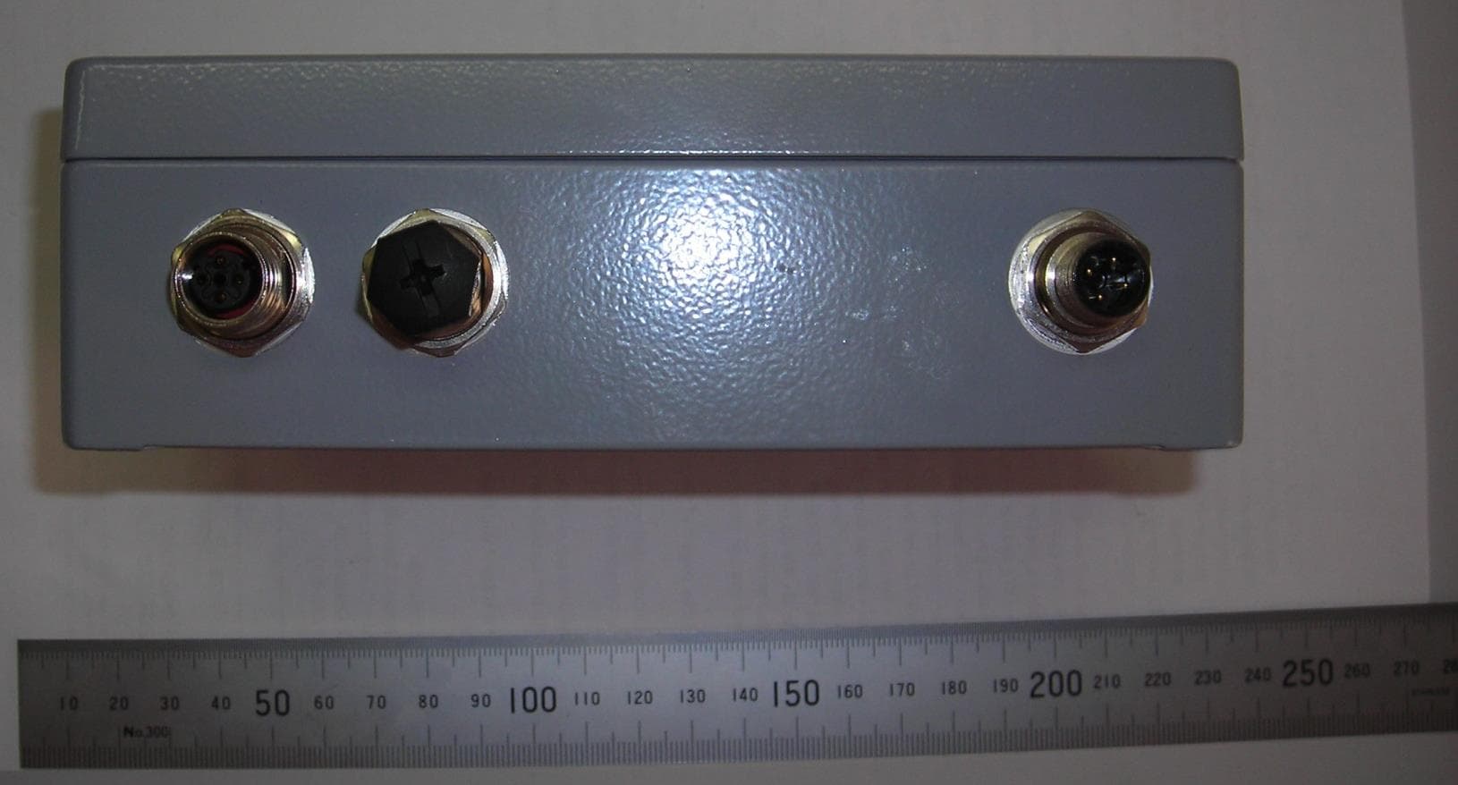
2ABZ5-4470328MODULE GP-CONTROL (Fleet for Underground) 447-0328
CATERPILLAR UNDERGROUND MINING PTY LTD
Click to zoom
Application Details
- Equipment Class
- UWB - Ultra Wideband Transmitter
- Date of Grant
- May 12, 2015
- Application Purpose
- Original Equipment
- Date of Application
- Mar 03, 2015
- Equipment Note
- MODULE GP-CONTROL (Fleet for Underground) 447-0328
- Frequency Range
- 3177.00000000 - 4924.00000000
- Country
- Australia
Documents & Files
Document Text
Text extracted from the exhibit documents filed with the FCC. Open a document above to read the original.
Users Manual
© 2014 Caterpillar Inc. 1 THE INFORMATION CONTAINED HEREIN IS THE PROPERTY OF CATERPILLAR UNDERGROUND MINING PTD LTD. WITHOUT WRITTEN PERMISSION, ANY COPYING, TRANSMITTAL TO OTHERS, AND ANY USE EXCEPT THAT FOR WHICH IT IS LOANED, IS PROHIBITED Confidential Yellow Creation Date 27/02/14 Revision No: 00 Module Gp-Control 447-0328 (Fleet for Underground) User Manual (English) Module Gp-Control (Fleet for Underground) User Manual (English) Part No: 447-0328 19 March, 2015 © 2014 Caterpillar Inc. 2 THE INFORMATION CONTAINED HEREIN IS THE PROPERTY OF CATERPILLAR UNDERGROUND MINING PTD LTD. WITHOUT WRITTEN PERMISSION, ANY COPYING, TRANSMITTAL TO OTHERS, AND ANY USE EXCEPT THAT FOR WHICH IT IS LOANED, IS PROHIBITED Confidential Yellow Creation Date 27/02/14 Revision No: 00 Module Gp-Control 447-0328 (Fleet for Underground) User Manual (English) Change History Date Version 19 March 2015 Draft 1.1 Information in this document is subject to change without notice. While every effort has been made to ensure that the information contained within this document and the features and changes described are accurate, Caterpillar cannot accept any type of liability for errors in, or omissions arising from, the use of this information. This document and all related documentation are the property of Caterpillar and may not be reproduced, transferred, sold, or otherwise disposed of, without the written permission of the owners. Safety Warnings This device complies with Industry Canada licence-exempt RSS standard(s). Operation is subject to the following two conditions: (1) this device may not cause interference, and (2) this device must accept any interference, including interference that may cause undesired operation of the device. Le présent appareil est conforme aux CNR d'Industrie Canada applicables aux appareils radio exempts de licence. L'exploitation est autorisée aux deux conditions suivantes: (1) L'appareil ne doit pas produire de brouillage, et (2) L'utilisateur de l'appareil doit accepter tout brouillage radioélectrique subi, même si le brouillage est susceptible d'en compromettre le fonctionnement. © 2014 Caterpillar Inc. 3 THE INFORMATION CONTAINED HEREIN IS THE PROPERTY OF CATERPILLAR UNDERGROUND MINING PTD LTD. WITHOUT WRITTEN PERMISSION, ANY COPYING, TRANSMITTAL TO OTHERS, AND ANY USE EXCEPT THAT FOR WHICH IT IS LOANED, IS PROHIBITED Confidential Yellow Creation Date 27/02/14 Revision No: 00 Module Gp-Control 447-0328 (Fleet for Underground) User Manual (English) The Module Gp Control 447-0328 is a designed for Caterpillar Inc. Fleet for Underground applications. It uses a P412 Time Domain PulsON® Ranging and Communications Module. The P412 is an Ultra Wide Band (UWB) transceiver that is used to provide reliable distance measurements at a high update rate. It is designed to communicate between two or more P412’s. The Module Gp Control 447-0328 transmits and receives trains of RF pulses at a nominal rate of 10MHz. This module uses the Two Way Time of Flight (TW-TOF) to measure distance. The module requesting the range measurement (the Requester) will transmit a packet of pulses that will be received by one or more units (the Responders). The Responder will then measure the leading edge of the waveform and will transmit this information in a return responding packet. This return packet is returned after a precise delay. The Requester will then determine the leading edge of the received waveform. The time between the leading edge measurements less the fixed delay is twice the distance between the units. The result is divided by two and multiplied by the speed of light results in the distance between the Responder and the Requester. Certification: FCC Compliant (FCC 15.519) – UWB Emissions FCC Compliant (FCC 15.109) – Class A digital device FCC Compliant Part 15, Subpart C, Subpart F for Ultra Wide Band Intentional Radiators © 2014 Caterpillar Inc. 4 THE INFORMATION CONTAINED HEREIN IS THE PROPERTY OF CATERPILLAR UNDERGROUND MINING PTD LTD. WITHOUT WRITTEN PERMISSION, ANY COPYING, TRANSMITTAL TO OTHERS, AND ANY USE EXCEPT THAT FOR WHICH IT IS LOANED, IS PROHIBITED Confidential Yellow Creation Date 27/02/14 Revision No: 00 Module Gp-Control 447-0328 (Fleet for Underground) User Manual (English) Specifications Power supply Wide range power supply, from 9V to 60VDC, 8W min, with polarity protection. M12 4-pole connector Ethernet interface Number of ports 2 Type of ports 10 BASE T or 100 BASE Tx Two Ultra-lock® M12 4-pole female connectors Bandwidth (Effective) 3.18GHz – 4.0GHz The bandwidth is defined as the frequency band bounded by the points that are 10dB below the highest radiated emission. Program - USB Interface Micro B connector (USB 2.0) RF Filtering Filtering in the presence of 2.4 and 5.8GHz Signals © 2014 Caterpillar Inc. 5 THE INFORMATION CONTAINED HEREIN IS THE PROPERTY OF CATERPILLAR UNDERGROUND MINING PTD LTD. WITHOUT WRITTEN PERMISSION, ANY COPYING, TRANSMITTAL TO OTHERS, AND ANY USE EXCEPT THAT FOR WHICH IT IS LOANED, IS PROHIBITED Confidential Yellow Creation Date 27/02/14 Revision No: 00 Module Gp-Control 447-0328 (Fleet for Underground) User Manual (English) Indicator Status Lights Indicator Status Light – Status/Diag Amber LED Toggles 1Hz Indicates that the module has passed the Built-in Test (BIT) Amber LED Flashing 10Hz Built-In Test (BIT) Failed Green LED Initially off the green LED will blink rapidly and then flashes constantly Green LED Flashing Clock signal is being received Green LED On solid or Off Indicates a failure condition Indicator Status Light - LAN1 and LAN2 LED Green Flashing The ACT LEDs indicate that there is activity in the respective Ethernet port. USB 2.0 Micro B connector Interface Signals names Pin 1 : +VE Pin 2 : D- (Data -) Pin 3 : D+ (Data +) Pin 4 : -VE (Ground) © 2014 Caterpillar Inc. 6 THE INFORMATION CONTAINED HEREIN IS THE PROPERTY OF CATERPILLAR UNDERGROUND MINING PTD LTD. WITHOUT WRITTEN PERMISSION, ANY COPYING, TRANSMITTAL TO OTHERS, AND ANY…
Text truncated - open the document above for the full version.
Test Report
BROADSPEC UWB ANTENNA Time Domain’s BroadSpec TM is a planar elliptical dipole antenna designed to be used with the PulsON 400 (P400) ultra wideband module. It has a standard male SMA connector that allows it to be connected to one of the P400 module’s two antenna ports. Performance Specification Radiated Waveform: 500ps monocycle; 1 ns waveform Pattern: Omni in azimuth to +/- 1.5dB Polarization: VSWR ~ 1.75:1; S11 ~-12 dB Gain: Nominally ~3dBi Phase Response: Linear Efficiency: Nominally ~90% Antenna Beam Patterns Figure 1 below shows the antenna azimuth beam pattern, and Figure 2 illustrates the elevation beam pattern. For the azimuth beam pattern, 0 and 180 degrees represent the flat face of the antenna ("boresight”), and 90 and 270 degrees represent the edge of the antenna. Note that when two radios at the same elevation are rotated so the flat sides of the antennas face one another, radio performance will be approximately 6 dB higher than when the antennas are edge-on. Fig. 1 Azimuth Beam Pattern for a) 3 GHz, Fig. 2 Elevation Beam Pattern for a) 3GHz, b) 4 GHz, c) 5 GHz, and d) 6 GHz b) 4 GHz, c) 5 GHz, and d) 6 GHz 320-0385A March 2011 θ y = 90 ° z y = 270 ° FOR MORE INFORMATION Cummings Research Park 1.256.922.9229 phone 4955 Corporate Drive1.256.922.0387 fax Suite 101 Huntsville, Alabama 35805 www.timedomain.com
Test Report
Engineering Test Report No. 1402455-01 Measurement of RF Emissions from a 447-0328 PulsON 412 Ultra Wide Band (UWB) Transmitter For Caterpillar Underground Mining Pty Ltd Building D 53-55 Main Road Wivenhoe Tasmania, AUSTRALIA 7320 P.O. Number 4600266839 Date Tested July 23-25, 2014 and August 28, 2014 Test Personnel Richard King Test Specification FCC "Code of Federal Regulations” Title 47 Part15, Subpart F Test Report By: Richard King EMC Engineer Approved By: Raymond J. Klouda Registered Professional Engineer of Illinois - 44894 Elite Electronic Engineering, Inc. 1516 Centre Circle Downers Grove, IL 60515 Tel : (630) 495-9770 Fax: (630) 495-9785 www.elitetest.com Engineering Test Report No. 1402455-01 TABLE OF CONTENTS PARAGRAPH DESCRIPTION OF CONTENTS PAGE NO. THIS REPORT SHALL NOT BE REPRODUCED, EXCEPT IN FULL, WITHOUT THE WRITTEN APPROVAL OF ELITE ELECTRONIC ENGINEERING INCORPORATED. Page 2 of 68 1. Introduction ................................................................................................................................................... 5 1.1. Scope of Tests ..................................................................................................................................... 5 1.2. Purpose ............................................................................................................................................... 5 1.3. Deviations, Additions and Exclusions .................................................................................................. 5 1.4. EMC Laboratory Identification ............................................................................................................. 5 1.5. Laboratory Conditions.......................................................................................................................... 5 2. Applicable Documents .................................................................................................................................. 5 3. EUT Setup and Operation ............................................................................................................................ 5 3.1. General Description ............................................................................................................................. 5 3.1.1. Power Input ................................................................................................................................. 5 3.1.2. Peripheral Equipment ................................................................................................................. 6 3.1.3. Signal Input/Output Leads .......................................................................................................... 6 3.1.4. Grounding ................................................................................................................................... 6 3.2. Software ............................................................................................................................................... 6 3.3. Operational Mode ................................................................................................................................ 6 3.4. EUT Modifications ................................................................................................................................ 6 4. Test Facility and Test Instrumentation ......................................................................................................... 6 4.1. Shielded Enclosure .............................................................................................................................. 6 4.2. Test Instrumentation ............................................................................................................................ 6 4.3. Calibration Traceability ........................................................................................................................ 6 4.4. Measurement Uncertainty ................................................................................................................... 6 5. Test Procedures ........................................................................................................................................... 7 5.1. Ultra Bandwidth Requirements ............................................................................................................ 7 5.1.1. Requirements .............................................................................................................................. 7 5.1.2. Procedures .................................................................................................................................. 7 5.1.3. Results ........................................................................................................................................ 8 5.2. Radiated Emissions Above 960MHz ................................................................................................... 8 5.2.1. Requirements .............................................................................................................................. 8 5.2.2. Procedures .................................................................................................................................. 8 5.2.3. Results ........................................................................................................................................ 9 5.3. Radiated Emissions in the GPS Receive Band ................................................................................... 9 5.3.1. Requirements .............................................................................................................................. 9 5.3.2. Procedures .................................................................................................................................. 9 5.3.3. Results .....................................................................................…
Text truncated - open the document above for the full version.
Test Setup Photos
Engineering Test Report No. 1402455-01 Page 15 of 68 Figure 2 Test Setup for Radiated Emissions, 30MHz to 1GHz – Horizontal Polarization Test Setup for Radiated Emissions, 30MHz to 1GHz – Vertical Polarization Engineering Test Report No. 1402455-01 Page 16 of 68 Figure 3 Test Setup for Radiated Emissions, Above 1GHz – Horizontal Polarization at 1Meter Test Setup for Radiated Emissions, Above 1GHz – Vertical Polarization at 1Meter
Contact Information
Applicant
SHANE MAY(MR)
Technical Contact
CATERPILLAR UNDERGROUND MINING PTY LTDNathan Williams
[email protected]+6136432
2-8 HOPKINSON ST · BURNIE, TASMANIA · Australia
Non-Technical Contact
CATERPILLAR UNDERGROUND MINING PTY LTDScott Jackson
[email protected]+61364329316
Test Firm
Elite Electronic Engineering Inc.Kevin Halpin
Technical Specifications
| # | Rule Parts | Frequency Range | Power Output |
|---|---|---|---|
| 1 | 15F | 3.18 GHz - 4.92 GHz | - |
Other Applications from CATERPILLAR UNDERGROUND MINING PTY LTD
2ABZ53667696
Dec 16, 20143667696 (WLg-ABOARD/N/CAT)
Equipment Class
DTS - Digital Transmission System