2AC2E-68M03JN5168 Standard Power ZigBee Module with u-FL connector
Meshreen Technology Ltd.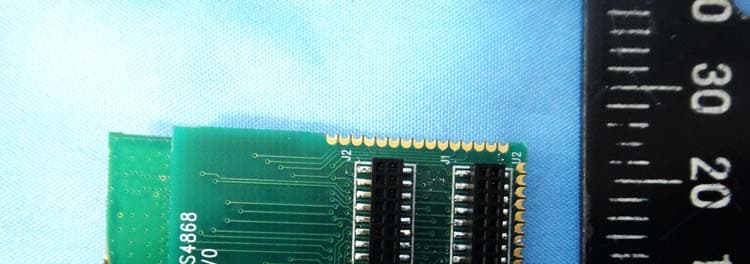
Click to zoom
Application Details
- Equipment Class
- DXX - Part 15 Low Power Communication Device Transmitter
- Date of Grant
- Oct 06, 2014
- Application Purpose
- Original Equipment
- Date of Application
- Oct 06, 2014
- Equipment Note
- JN5168 Standard Power ZigBee Module with u-FL connector
- Frequency Range
- 2405.00000000 - 2480.00000000
- Company
- Meshreen Technology Ltd.
- Country
- Taiwan
Documents & Files
Document Text
Text extracted from the exhibit documents filed with the FCC. Open a document above to read the original.
Users Manual
©Meshreen DS‐MS5168 / [email protected] 1 Meshreen MS5168 ZigBee Module MS5168-Mxx series USER MANUAL FCC ID :2AC2E-68M03 ©Meshreen DS‐MS5168 / [email protected] 2 Content 1. Introduction ......................................................................................................................................................... 3 1.1 Variants ................................................................................................................................................. 3 2. Specification ........................................................................................................................................................ 4 2.1 Pin configurations ................................................................................................................................. 5 2.2 Pin Assignment ...................................................................................................................................... 6 2.3 .Pin Description ..................................................................................................................................... 7 2.4 Power Supplies ...................................................................................................................................... 7 3. Electrical Characteristics ...................................................................................................................................... 8 3.1 Maximum Ratings ................................................................................................................................. 8 3.2 Operation Conditions ............................................................................................................................ 8 4. Outline Drawing ................................................................................................................................................... 9 4.1 Module PCB Footprint ......................................................................................................................... 12 5. Optimal PCB placement of the MS5168‐M00/M05 Module ............................................................................. 13 6. Reflow Profile .................................................................................................................................................... 14 7. Ordering Information ........................................................................................................................................ 15 8. Version Control .................................................................................................................................................. 15 Figure 1 Pin Configuration (top view) ................................................................................................................... 5 Figure 2 MS5168‐M00 Outline Drawing ....................................................................................................................... 9 Figure 3 MS5168‐M04 Outline Drawing ....................................................................................................................... 9 Figure 4 MS5168‐M03 outline drawing ...................................................................................................................... 10 Figure 5 MS5168‐M04/M05 Outline Drawing ............................................................................................................. 11 Figure 6 PCB footprint ................................................................................................................................................. 12 Figure 7 Optimal PCB placement ................................................................................................................................ 13 Figure 8 Module Reflow profile reference .................................................................................................................. 14 Table 1 Meshreen module variants ............................................................................................................................... 3 Table 2 Module specification ........................................................................................................................................ 4 Table 3 Pin Assignment .............................................................................................................................................. 6 Table 4 Maximum Ratings ............................................................................................................................................. 8 Table 5 Operation Conditions ....................................................................................................................................... 8 ©Meshreen DS‐MS5168 / [email protected] 3 1. Introduction The MS5168‐001‐Myy family is a range of ultra‐low power, high performance surface mount modules targeted at IEEE 802.15.4, JenNet‐IP, ZigBee Light Link, ZigBee Smart Energy and RF4CE networking applications, enabling users to realize products with minimum time to market and at the lowest cost. They remove the need for expensive and lengthy development of custom RF board designs and test suites. The modules use NXP’s MS5168 wireless microcontroller to provide a comprehensive solution with large memory, high CPU and radio performance and all RF components included. All that is required to develop and manufacture wireless control or sensing products is to connect a power supply and peripherals such as switches, actuators and sensors, considerably simplifying product development. 1.1 Variants Variant Description MS5168M00 JN5168 IEEE802.15.4/ZigBee Standard Power Module with embedded PCB antenna MS5168M03 JN5168 IEEE802.15.4/ZigBee Standard Power Module with μ-FL connector MS5168M04 JN5168 IEEE802.15.4/ZigBee High Power Module with μ-FL connector MS5168M05 JN5168 IEEE802.15.4/ZigBee Hi…
Text truncated - open the document above for the full version.
External Photos
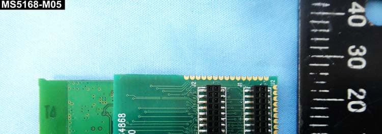
1 of 3 External Photos Model Number: MS5168-M03 FCC ID: 2AC2E-68M03 2 of 3 EUT Photo 1 ) EUT Photo 2 ) Antenna 3 of 3 EUT Photo 3 ) EUT Photo 4 )
ID Label/Location Info
ID Label info & Label Location FCC ID : 2AC2E-68M03
Internal Photos
1 of 3 Internal Photos Model Number: MS5168-M03 FCC ID: 2AC2E-68M03 2 of 3 EUT Photo 1 ) EUT Photo 2 ) 3 of 3 EUT Photo 3 )
Test Report
FCC 47 CFR PART 15 SUBPART C Product Type : JN5168 Standard Power ZigBee Module with u-FL connector Applicant : Meshreen Technology Ltd. Address : No.11-3, Xiashe, Guishan Township, Taoyuan County 333, Taiwan Trade Name : Meshreen Model Number : MS5168-M03 Test Specification : FCC 47 CFR PART 15 SUBPART C: Oct., 2013 ANSI C63.4:2009 47 CFR § 2.1091 47 CFR §1.1310 ANSI / IEEE Std.C95.1-1992 Receive Date : Aug. 13, 2014 Test Period : Aug. 19 ~ Sep. 09, 2014 Issue Date : Oct. 06, 2014 Issue by A Test Lab Techno Corp. No. 140-1, Changan Street, Bade City, Taoyuan County 334, Taiwan R.O.C. Te l:+886-3-2710188 / Fax:+886-3-2710190 T aiwan Accreditation Foundation accreditation number: 1330 Note: This report shall not be reproduced except in full, without the written approval of A Test Lab Techno Corp. This document may be altered or revised by A Test Lab Techno Corp. personnel only, and shall be noted in the revision section of the document. The client should not use it to claim product endorsement by TAF, or any government agencies. The test results in the report only apply to the tested sample. Report Number: 1409FR16 1 of 40 A Test Lab Techno Corp. Revision History Rev. Issue Date Revisions Revised By 00 Oct. 06, 2014 Initial Issue Report Number: 1409FR16 2 of 40 A Test Lab Techno Corp. Verification of Compliance Issued Date: 10/06/2014 Product Type : JN5168 Standard Power ZigBee Module with u-FL connector Applicant : Meshreen Technology Ltd. Address : No.11-3, Xiashe, Guishan Township, Taoyuan County 333, Taiwan Trade Name : Meshreen Model Number : MS5168-M03 FCC ID : 2AC2E-68M03 EUT Rated Voltage : DC 3.3V Test Voltage : 120 Vac / 60 Hz Applicable Standard : FCC 47 CFR PART 15 SUBPART C: Oct., 2013 ANSI C63.4:2009 47 CFR § 2.1091 47 CFR §1.1310 ANSI / IEEE Std.C95.1-1992 Test Result : Complied Performing Lab. : A Test Lab Techno Corp. No. 140-1, Changan Street, Bade City, Taoyuan County 334, Taiwan R.O.C. Te l:+886-3-2710188 / Fax:+886-3-2710190 T aiwan Accreditation Foundation accreditation number: 1330 http://www.atl-lab.com.tw/e-index.htm The above equipment was tested by A Test Lab Techno Corp. The test data, data evaluation, test procedures, and equipment configurations shown in this report were made in accordance with the procedures given in ANSI C63.4: 2009 and the energy emitted by the sample tested as described in this report is in compliance with the requirements of FCC Rules Part 15.207, 15.209, 15.247 . The test results of this report relate only to the tested sample identified in this report. Approved By : Reviewed By : (Manager) (Fly Lu) (Testing Engineer) (Eric Ou Yang) Report Number: 1409FR16 3 of 40 A Test Lab Techno Corp. TABLE OF CONTENTS 1 General Information ....................................................................................................................................... 6 2 EUT Description ............................................................................................................................................. 7 3 Test Methodology .......................................................................................................................................... 8 3.1. Mode of Operation.................................................................................................................................. 8 3.2. EUT Exercise Software.......................................................................................................................... 8 3.3. Configuration of Test System Details ..................................................................................................... 9 3.4. Test Site Environment ............................................................................................................................ 9 4 Conducted Emission Measurement ........................................................................................................... 10 4.1. Limit ...................................................................................................................................................... 10 4.2. Test Instruments ................................................................................................................................... 10 4.3. Test Setup............................................................................................................................................. 10 4.4. Test Procedure ......................................................................................................................................11 4.5. Test Result.............................................................................................................................................11 5 Radiated Emission Measurement............................................................................................................... 12 5.1. Limit ...................................................................................................................................................... 12 5.2. Test Instruments ................................................................................................................................... 12 5.3. Setup .................................................................................................................................................... 13 5.4. Test Procedure ..................................................................................................................................... 14 5.5. Test Result............................................................................................................................................ 16 6 Maximum Conducted Output Power Measurement.................................................................................. 19 6.1. Limit ...................................................................................................................................................... 19 6.2. Test Setup......…
Text truncated - open the document above for the full version.
Test Setup Photos
Part 15C Test Setup Photographs Radiated Emissions Test Configuration: Below 1GHz _ Front View Below 1GHz _ Rear View Report Number: 1409FR16 1 of 3 A Test Lab Techno Corp. Above 1GHz _ Front View Above 1GHz _ Rear View Report Number: 1409FR16 2 of 3 A Test Lab Techno Corp. Close View Report Number: 1409FR16 3 of 3 A Test Lab Techno Corp.
Contact Information
Applicant
Bruce Chen(Director)
Test Firm
Eurofins E&E Wireless Taiwan Co., LtdFly LU
Technical Specifications
| # | Rule Parts | Frequency Range | Power Output |
|---|---|---|---|
| 1 | 15C | 2.40 GHz - 2.48 GHz | 500.00 µW |
Other Applications from Meshreen Technology Ltd.
2AC2E-68M04
Oct 06, 2014JN5168 High Power ZigBee Module with u-FL connector/with embedded antenna
Equipment Class
DXX - Part 15 Low Power Communication Device Transmitter