2AC2N-DFTOUCHWRTime & Attendance Device
Ceridian Canada Ltd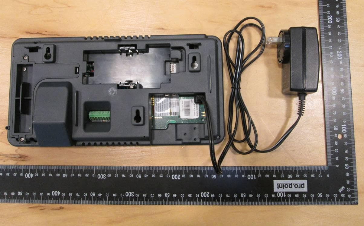
Click to zoom
Application Details
- Equipment Class
- DXX - Part 15 Low Power Communication Device Transmitter
- Date of Grant
- Nov 24, 2014
- Application Purpose
- Original Equipment
- Date of Application
- Nov 17, 2014
- Equipment Note
- Time & Attendance Device
- Frequency Range
- 13.56000000 - 13.56000000
- Company
- Ceridian Canada Ltd
- Country
- Canada
Documents & Files
Document Text
Text extracted from the exhibit documents filed with the FCC. Open a document above to read the original.
Users Manual
Ceridian’s Dayforce Touch Clock User Manual [ENG] WARNING: This manual contains information on limitations regarding product use, function and information on the limitation and liability of the manufacturer. Read the entire manual carefully. DF Touch Page 2 of 23 Read and save these instructions! Follow all warnings and instructions specified within this document and/or on the equipment. Always ensure you obtain the latest version of the User Guide. Updated versions of this User Guide are available by contacting your Ceridian HCM administrator. 1 I MPORT AN T SAFET Y INST RUC T I ON S To reduce the risk of fire, electric shock and/or injury, observe the following safety precautions: Do not spill any type of liquid on the equipment. Do not attempt to service this product yourself. Opening or removing the cover may expose you to dangerous voltage or other risk. Refer servicing to qualified service personnel. Never open the device yourself. Do not touch the equipment and its connected cables during an electrical storm; there may be a risk of electric shock. 2 REG ULAR MAI NT EN ANC E AN D T ROUB LESHOOT I N G Keep your DF Touch Clock in optimal condition by following all the instructions that are included within this manual and/or marked on the product. 3 HAN DLI N G PREC AUTI ON S Do not subject the touchscreen to mechanical shock (e.g., dropping or striking). Mechanical shock could damage the glass display. If the touchscreen glass is damaged, the liquid crystal fluid inside could leak out. Avoid contact with the liquid crystal fluid. DF Touch Page 3 of 23 If the liquid crystal fluid comes into contact with your skin or clothes, promptly wash it off using soap and water. Do not apply excessive force to the display surface or adjoining areas. Excessive force will distort the image on the display. Do not use hard or sharp implements to operate the touchscreen. Operating the touch screen with implements harder than a finger could scratch the display. Do not attempt to disassemble the LCD Module. 4 C LEAN I NG If the display surface is contaminated, moisten a use a soft cloth and isopropyl alcohol to clean it. Other cleaners such as ketone (e.g., acetone), and/or aromatic solvents (e.g., benzene und toluene) may damage the display. Do not use abrasives, thinners, solvents or aerosol cleaners (i.e., spray polish). Any aromatic solvents, keytones etc. that may enter through holes in the touch panel will cause damage. Keep the ventilation slots clear of obstructions, dust buildup and liquids. Do not spray liquids directly into the unit; avoid liquids entering into the unit. WARNING: This equipment shall be installed and used within an environment that provides the pollution degree max 2 and over- voltages category II non-hazardous locations, indoor only. It is designed to be installed, serviced and/or repaired by service persons only [service person is defined as a person having the appropriate technical training and experience necessary to be aware of the hazards to which a person may be exposed in performing a task and of measures to minimize the risks to other persons]. With the exception of the battery, the end user cannot replace any of the parts within the unit. These safety instructions should not prevent you from contacting the installer or DF Touch Page 4 of 23 Dayforce HCM administrator to obtain any further clarification and/or answers to your concerns. DF Touch Page 5 of 23 5 MAI N T EN AN C E With normal use, the system requires minimal maintenance. We recommend, however, that the standby batteries be replaced every 3-5 years. 6 SPEC I FI C AT I ON S This document describes the technical specifications of the DF Touch clock terminal. 6 .1 D isplay an d Key pad Capacitive Touch, 7 inch, 800x480 pixels, hardened glass surface. 6 .2 P ro cesso r CPU: 1GHz Dual Core ARM Cortex A9 RAM: Memory 1GByte 528 MHz SoDIMM, Non-volatile FLASH memory 8GByte 6 .3 Env iro nm ent Operating temperature: 0° to 40°C (32° to 104°F) Storage temperature: -30° to 80°C (-22° to 176°F) Humidity: 10% to 90% relative humidity, non condensing. 6 .4 P o wer Supply Input Power Jack: 24 VDC ±5%, 0.75 A, 20 W maximum 2.5mm barrel connector, center positive. Power over Ethernet (PoE) DF Touch Page 6 of 23 IEEE 802.3at Type2, absolute operating input voltage 42.5-57VDC, nominal draw 10Watts, max 20Watts. Optional: External power supply Input voltage 110-250 VAC, 0.5 A, 50/60Hz Optional: Battery backup with Charger Discharge life: 1.5 hours at 23°C (73°F) Charge time: 16Hrs (on first use) Charging (normal): 0° to 45°C (32° to 113°F) Storage: -20° to 35°C (-4° to 95°F) Discharging (battery: -20° to 60°C (-4° to 140°F) 6 .5 Operatin g Sy stem Android 4.0.3 (ICS) 6 .6 Appl icatio n P ro gram s Dayforce Clock Program Dayforce Self Service 6 .7 Enclo sure Plastic ABS/PVC Composite 6 .8 Wall-m o unt Optio ns 10 Degree hinged plastic ABS/PVC 10 Degree metal 40 Degree metal (extra cost – good for camera use) 6 .9 Internet Co n nectiv ity IEEE 802.3 10/100BASE-T/1000BASE-T Ethernet using TCP/IP communication protocol and CAT-5 cable, cable lengths between DF Touch Page 7 of 23 the terminal and an Ethernet network hub can be up to 328 wire- feet. DHCP (Dynamic Host Configuration Protocol) is implemented to assign IP addresses for the terminal, host and router. Static IP addresses may also be assigned manually via the touch screen. The terminal supports the use of DNS servers to convert host names to host IP addresses in both DHCP and static IP modes. Optional Wi-Fi 802.11 b/g/n 6 .1 0 Cam era Integrated camera with 3 Megapixels resolution and torch flash. 6 .1 1 L ED Three-color LED (red, green, blue) for status display 6 .1 2 External USB po rts Two USB ports For service use only 6 .1 3 Optio nal rea ders & M o dules (extra co st) Fingerprint Biometric reader Barcode slot reader (visible or infra-red light) Magnetic slot reader Proximity reader (125Khz or 13.5Mhz – for HID Proxpoint™, iClass™, Mifare™, NFC) 6 .1…
Text truncated - open the document above for the full version.
Cover Letter(s)
Ceridian Canada Ltd 4110 Yonge St. Suite 604 Toronto, ON. M2P 2B7 Request for Confidentiality Date: Aug 22, 2014 Subject: Confidentiality Request for: ______2AC2N-DFTOUCHWR______ Pursuant to FCC 47 CRF 0.457(d) and 0.459 and IC RSP-100, Section 10, the applicant requests that a part of the subject FCC application be held confidential. Type of Confidentiality Requested Exhibit Short Term Permanent Block Diagrams Short Term External Photos Short Term Permanent Internal Photos Short Term Permanent Operation Description/Theory of Operation Short Term Permanent Parts List & Placement/BOM Short Term Permanent Tune-Up Procedure Short Term Permanent Schematics Short Term Test Setup Photos Short Term Permanent User’s Manual Ceridian Canada Ltd has spent substantial effort in developing this product and it is one of the first of its kind in industry. Having the subject information easily available to "competition" would negate the advantage they have achieved by developing this product. Not protecting the details of the design will result in financial hardship. Permanent Confidentiality: The applicant requests the exhibits listed above as permanently confidential be permanently withheld from public review due to materials that contain trade secrets and proprietary information not customarily released to the public. NOTE for Industry Canada Applications: The applicant understands that until such time that IC distinguishes between Short Term and Permanent Confidentiality, either type of marked exhibit above will simply be marked Confidential when submitted to IC.
External Photos
EUT – External view, side 1 (With power supply) EUT – External view, side 2 (With power supply) EUT – External view Power supply label
ID Label/Location Info
Label Location
ID Label/Location Info
Model: DFTouch (WR) FCC ID: 2AC2N-DFTOUCHWR IC: 12286A-DFTOUCHWR Contains TX FCC ID: RYK-WUBR170GNM TX IC: 6158A-WUBR170GNM +24V/0.75A This device complies with part 15 of the FCC Rules. Operation is subject to the following two conditions: (1) This device may not cause harmful interference, and (2) this device must accept any interference received, including interference that may cause undesired operation.
Internal Photos
EUT – Internal view 1 1 4 5 2.4 GHz Antenna RFID Antenna (located underneath) 9 EUT – Internal view 2 1 2 4 5 9 EUT – Internal view 3 2 3 4 5 2.4 GHz Antenna RFID Antenna 9 EUT – Internal view 4 1 2 3 4 5 6 EUT – Internal view 5 Board 6 (LCD screen) removed from chassis 6 1 Board #1 (fingerprint reader) as seen in photos EUT – Internal view 1-4 Board #1 (fingerprint reader board) as seen in photos EUT – Internal view 1-4 Side 1 Board #1 (fingerprint reader board) as seen in photos EUT – Internal view 1-4 Side 2 Board #1 (fingerprint reader board) as seen in photos EUT – Internal view 1-4, Side 2, shield off. Board #2 (RFID card reader) as seen in photos EUT – Internal view 2-4 Side 1 Board #2 (RFID card reader) as seen in photos EUT – Internal view 2-4 Side 2 Board #7 (daughter board of Board #2) as seen in photo Shown above, Side 2 7 Board #3 (RFID card reader antenna) as seen in photos EUT – Internal view 3-4 Side 1 Board #3(RFID card reader antenna) as seen in photos EUT – Internal view 3-4 Side 2 Board #4 (relay board) as seen in photos EUT – Internal view 1-4 Side 1 Board #4 (relay board) as seen in photos EUT – Internal view 1-4 Side 2 Board #5 (mainboard) as seen in photos EUT – Internal view 1-4 Side 1 Board #8 (2.4GHz board) as seen in previous photo. Side 1. 8 Board #8 (2.4GHz board), Shown with antenna connected. Board #8 (2.4GHz board), Side 1, Shield removed Board #8 (2.4GHz board), Side 2 Board #5 (mainboard) as seen in photos EUT – Internal view 1-4 Side 2 Board #6 (LCD panel) as seen in photos EUT – Internal view 4 & 5 Side 1 Board #6 (LCD panel) as seen in photos EUT – Internal view 4 & 5 Side 2 Board #9 (magnetic card reader) as seen in photos EUT – Internal view 1-3 Board #9 (magnetic card reader) Side 1 Board #9 (magnetic card reader) Side 1, shield removed Board #9 (magnetic card reader) Side 2
Operational Description
DFTOUCH General Theory of Operation This device is a time keeping system for the recording of employee work hours. The device is a microprocessor system that runs the Android operating system and a custom application that takes care of the employee interaction through a Graphical User Interface. As the person enters the information as to their attendance, this information is sent to a local server or a Cloud server. The device is connected to the aforementioned server via either a wired Ethernet connection or wireless. Device power may come from one of three sources. 1) AC Adapter, 2) PoE power from Ethernet cable, 3) On board Battery (which is trickle charged from either source #1 or #2). Additionally, the device can use for user authentication, fingerprint recognition, facial recognition through a camera, RFID badge reader, and barcode/magswipe badge reader. Powering up the unit takes approximately 30s. After power up, an individual may approach the unit, enter in whether they are starting their work day or ending it, and then offer some sort of authentication as described above. Once the information has been validated, it is sent to the server. Description of RFID The 125 kHz antenna transmits detection bursts every 250ms for 50ms. Once detecting a valid 125 kHz RFID card, it sends out a steady carrier of 125 kHz to read back the card data via PSK. This is repeated every second until the card is removed and then it goes back to detection mode. Concurrent to the 125 kHz detection mode, the 13.56 MHz section transmits a detection carrier. Once a card is detected, it sends a series of encoded PSK data to the card and reads back the card data. Both transmitters transmit at the same time, however only one card type can be present at any time.
RF Exposure Info
Maximum Permissible Exposure Ceridian HCM Model: DFTouch (WR) FCC ID: 2AC2N-DFTOUCHWR IC: 12286A-DFTOUCHWR Purpose The purpose of this test is to ensure that the RF energy intentionally transmitted, in terms of power density emitted from the EUT at a stated operating distance does not exceed the limits listed below as defined in the applicable test standard, as calculated based upon readings obtained during testing. This helps protect human exposure to excessive RF fields. Limit(s) and Method The limits, as defined in FCC 1.1310 Table 1 (B) limits for general public exposure was applied. The limit for the frequency range of 1.34 MHz to 30 MHz is 180/f 2 mW/cm 2 , and the limit for the frequency range of 1.5 GHz to 100 GHz is 1.0 mW/ cm 2 . The limit for the frequency range of 0.3 MHz to 1.34 MHz is 100 mW/cm 2 . Limits are not defined for frequencies < 0.3MHz, however the output power of the 125 kHz transmitter is low. The limit for MPE at 300 kHz is applied to determine compliance. Therefore, the limits for this device are as follows: MPE Limits Frequency Limit 125 kHz 100 mW/cm 2 13.56 MHz 0.97 mW/cm 2 2.4GHz 1.0 mW/cm 2 The distance used for calculations was 20cm, as this is the minimum distance an operator will be from the EUT during normal operation. Prediction methods from OET Bulletin 65, Edition 97-01 are applied. SAR test exclusion for simultaneous transmissions from FCC KDB447498 is applied. Results The EUT passed the requirements. The worst case calculated power density was 0.0134 mW/cm 2 . This is under the 1.0 mW/cm 2 requirement. Calculations for 15.247 device P d = (P*G)/(4*pi*R 2 ) Where: P = Power input into the antenna = 66mW as per grant for RYK-WUBR170GNM module. G = Power gain of antenna = 0.1 dBi = 1.02 (numeric) as per test report. R = 20cm P d = (66 mW * 1.02) / (4 * pi * 20 2 cm 2 ) P d = 0.0134 mW/cm 2 Calculations for 15.209 devices 13.56 MHz Device P d = (EIRP / (4*pi*R 2 ) Where: EIRP = Equivalent Isotropic Radiated Power = E(dBuV) – 95.2 E(dBuV) = 51.1 dBuV as per Radiated Emissions - 15.209 - Table 4. EIRP = 51.1 dBuV – 95.2 = -44.1 dBm = 0.000039 mW R = 20cm P d = (0.000039 mW) / (4 * pi * 20 2 cm 2 ) P d = 0.000000007 mW/cm 2 125 kHz Device P d = (EIRP / (4*pi*R 2 ) Where: EIRP = Equivalent Isotropic Radiated Power = E(dBuV) – 95.2 E(dBuV) = 79.1 dBuV as per Radiated Emissions - 15.209 - Table 4. EIRP = 79.1 dBuV – 95.2 = -16.1 dBm = 0.02455 mW R = 20cm P d = (0.02455 mW) / (4 * pi * 20 2 cm 2 ) P d = 0.000004884 mW/cm 2 Calculations for simultaneous transmission device As per FCC KDB447498 7.2: Simultaneous transmission MPE test exclusion applies when the sum of the MPE ratios for all simultaneous transmitting antennas incorporated in a host device, based on the calculated/estimated, numerically modeled or measured field strengths or power density, is ≤ 1.0. MPE ratio = Ratio of power density to MPE limit, at the test frequency = P d / (MPE limit) MPE ratio for 15.247 device = 0.0134 mW/cm 2 / 1.0 mW/cm 2 = 0.0134 MPE ratio for 15.209 device (13.56 MHz device) = 0.000000007 mW/cm 2 / 0.97 mW/cm 2 = 0.000000007 MPE ratio for 15.209 device (125 kHz device) = 0.000004884 mW/cm 2 / 100 mW/cm 2 = 0.000000049 0.0134 + 0.000000007 + 0.000000049 = 0.013400056 < 1.0 MPE test exclusion applies for simultaneous transmission.
Test Report
LAB REGISTRATION #6844A-3 FCC REGISTRATION #377448 Testing Laboratory Certificate #2555.01 Page 1 of 98 Report issue date: 10/9/2014 GEMC File #: GEMC-FCC-22013CR1 © Global EMC Inc. This test report shall not be reproduced except in full, without written approval of Global EMC Inc. This report is based on GEMC Template “FCC 15 247 Rev2.” Global EMC Inc. Labs EMC & RF Test Report As per RSS 210 Issue 8:2010 & FCC Part 15 Subpart C:2010 Unlicensed Intentional Radiators on the Ceridian DFTouch (WR) Raymond Lee Au, B.Eng Project Engineer Global EMC Inc. 11 Gordon Collins Dr. Gormley, ON L0H 1G0, Canada Ph: (905) 883-8189 Testing produced for See Appendix A for full customer & EUT details. Client CERIDIAN HCM Product DFTouch (WR) Standard(s) RSS 210 Issue 8:2010 / FCC Part 15 Subpart C 15:2014 Page 2 of 98 Report issue date: 10/9/2014 GEMC File #: GEMC-FCC-22013CR1 © Global EMC Inc. This test report shall not be reproduced except in full, without written approval of Global EMC Inc. Table of Contents Table of Contents ................................................................................................................... 2 Report Scope .......................................................................................................................... 3 Summary ................................................................................................................................ 4 Test Results Summary ....................................................................................................... 5 Justifications, Descriptions, or Deviations......................................................................... 6 Applicable Standards, Specifications and Methods ........................................................... 7 Sample calculation(s) ......................................................................................................... 8 Document Revision Status ................................................................................................. 8 Definitions and Acronyms ..................................................................................................... 9 Testing Facility .................................................................................................................... 10 Calibrations and Accreditations ....................................................................................... 10 Testing Environmental Conditions and Dates ................................................................. 11 Detailed Test Results Section .............................................................................................. 12 Radiated Emissions - Spurious ........................................................................................ 13 Radiated Emissions – Fundamental ................................................................................. 22 99% Bandwidth ................................................................................................................ 27 Radiated Emissions – Modularly Approved Transmitter Verification ............................ 30 Antenna Gain – Modularly Approved Transmitter Verification ..................................... 69 Power Line Conducted Emissions ................................................................................... 74 Appendix A – EUT Summary .............................................................................................. 80 Appendix B – EUT and Test Setup Photographs................................................................. 81 Client CERIDIAN HCM Product DFTouch (WR) Standard(s) RSS 210 Issue 8:2010 / FCC Part 15 Subpart C 15:2014 Page 3 of 98 Report issue date: 10/9/2014 GEMC File #: GEMC-FCC-22013CR1 © Global EMC Inc. This test report shall not be reproduced except in full, without written approval of Global EMC Inc. Report Scope This report addresses the EMC verification testing and test results of the Ceridian DFTouch (WR) device, herein referred to as EUT (Equipment Under Test). Testing is performed at Global EMC Labs. The EUT was tested for compliance against the following standards: RSS 210 Issue 8:2010 FCC Part 15 Subpart C:2014 Test procedures, results, justifications, and engineering considerations, if any, follow later in this report. The results contained in this report relate only to the item(s) tested. This report does not imply product endorsement by A2LA or any other accreditation agency, any government, or Global EMC Inc. Opinions/interpretations expressed in this report, if any, are outside the scope of Global EMC Inc accreditation. Any opinions expressed do not necessarily reflect the opinions of Global EMC Inc, unless otherwise stated. Client CERIDIAN HCM Product DFTouch (WR) Standard(s) RSS 210 Issue 8:2010 / FCC Part 15 Subpart C 15:2014 Page 4 of 98 Report issue date: 10/9/2014 GEMC File #: GEMC-FCC-22013CR1 © Global EMC Inc. This test report shall not be reproduced except in full, without written approval of Global EMC Inc. Summary The results contained in this report relate only to the item(s) tested. EUT FCC Certification #, FCC ID: 2AC2N-DFTOUCHWR EUT Industry Canada Certification #, IC: 12286A-DFTOUCHWR EUT Passed all tests performed. Yes (see test results summary) Tests conducted by Raymond Lee Au Client CERIDIAN HCM Product DFTouch (WR) Standard(s) RSS 210 Issue 8:2010 / FCC Part 15 Subpart C 15:2014 Page 5 of 98 Report issue date: 10/9/2014 GEMC File #: GEMC-FCC-22013CR1 © Global EMC Inc. This test report shall not be reproduced except in full, without written approval of Global EMC Inc. Test Results Summary Standard/Method Description Class/Limit Result FCC 15.203 Antenna Requirement Unique Pass See Justification FCC 15.205 RSS 210 (Table 1) Restricted Bands for intentional operation QuasiPeak Average Pass FCC 15.207 Power line conducted emissions QuasiPeak Average Pass FCC 15.209 RSS-210 (Table 2) Spurious Radiated emissions QuasiPeak Average Pass Overall Result P…
Text truncated - open the document above for the full version.
Test Setup Photos
Radiated Emissions Radiated Emissions 2 Radiated Emissions 3 Conducted Measurements Power Line Conducted Emissions
Contact Information
Applicant
Martin Ossip(Executive V.P.)
Technical Contact
Ceridian Canada Ltd.Martin Ossip
[email protected]416-987-2987
4110 Yonge Stree · Toronto, ON · Canada
Test Firm
Global EMC Inc.Scott Drysdale
Technical Specifications
| # | Rule Parts | Frequency Range | Power Output |
|---|---|---|---|
| 1 | 15C | 13.56 MHz - 13.56 MHz | - |