2AC35-MELODYGTXGuitar Wireless Mic
Acoustas Co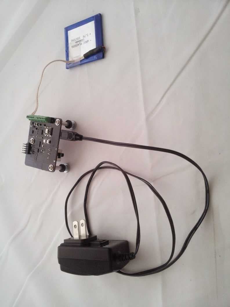
Click to zoom
Application Details
- Equipment Class
- DTS - Digital Transmission System
- Date of Grant
- Oct 14, 2014
- Application Purpose
- Original Equipment
- Date of Application
- Oct 13, 2014
- Equipment Note
- Guitar Wireless Mic
- Frequency Range
- 2406.00000000 - 2466.00000000
- Company
- Acoustas Co
- Country
- United States
Documents & Files
Document Text
Text extracted from the exhibit documents filed with the FCC. Open a document above to read the original.
Users Manual
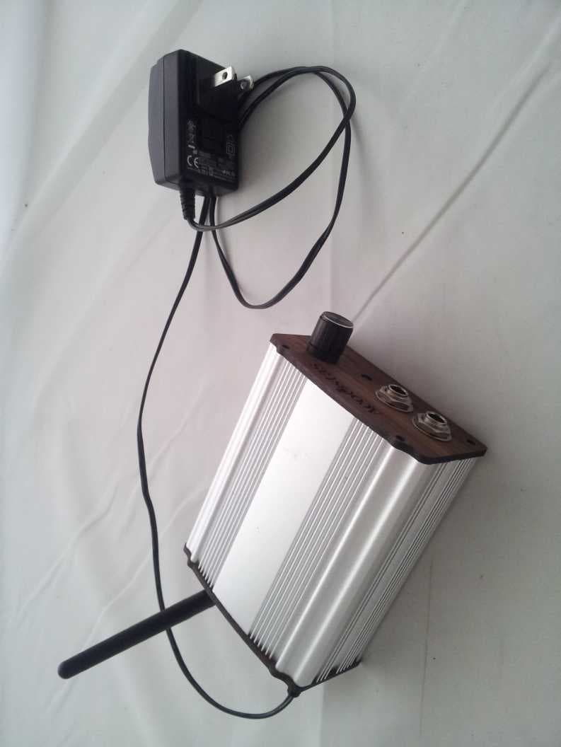
Melody-G Wireless Guitar Microphone Installation and Operation Manual 3300 W. Clay St., Richmond, VA, 23230 http://www.acoustas.com/ Thank you for your purchase of an Acoustas Melody-G. Please visit our website at http://www.acoustas.com/ for up-to-date information on the Melody-G and other products and to contact us with questions or comments. This manual will describe how to properly install, connect, and operate your versatile new wireless microphone. Transmitter (left) and receiver (right) The following should be included in your shipment: •Transmitter with three suspension pegs for mounting •Lithium-ion battery (square) with two-pin connector •Piezoelectric film microphone (rectangular) with three-pin connector •Receiver with attached 2.4GHz antenna •Standard-A to mini-B USB cable for use with both devices •USB right-angle adapter for use with the transmitter •Charging brick with USB port for use with both devices 2 3300 W. Clay St., Richmond, VA, 23230 http://www.acoustas.com/ Federal Communications Commission and Industry Canada Notices for the Melody-G Master Unit (Transmitter) The master unit can be identified by these markings: Model/FCC ID: 2AC35-MELODYGTX IC: 12297A-MELODYG The following notices are applicable: This device complies with Part 15 of the FCC Rules and with Industry Canada license-exempt RSS standard(s). Operation is subject to the following two conditions: (1) This device may not cause harmful interference, and (2) This device must accept any interference received, including interference that may cause undesired operation. Le présent appareil est conforme aux CNR d'Industrie Canada applicables aux appareils radio exempts de licence. L'exploitation est autorisée aux deux conditions suivantes: (1) l'appareil ne doit pas produire de brouillage, et (2) l'utilisateur de l'appareil doit accepter tout brouillage radioélectrique subi, même si le brouillage est susceptible d'en compromettre le fonctionnement. Note: Changes or modifications not expressively approved by the party responsible for compliance could void the user's authority to operate the equipment. This equipment has been tested and found to comply with the limits for a Class A digital device, pursuant to part 15 of the FCC Rules. These limits are designed to provide reasonable protection against harmful interference when the equipment is operated in a commercial environment. This equipment generates, uses, and can radiate radio frequency energy and, if not installed and used in accordance with the instruction manual, may cause harmful interference to radio communications. Operation of this equipment in a residential area is likely to cause harmful interference in which case the user will be required to correct the interference at his own expense. This device should not be co-located with any other antenna or transmitter. It should remain at least 3 centimeters (1-1/8 inches) from the user at all times while switched on in order to reduce harmful radio frequency exposure. 3 3300 W. Clay St., Richmond, VA, 23230 http://www.acoustas.com/ Federal Communications Commission and Industry Canada Notices for the Melody-G Slave Unit (Receiver) The slave unit can be identified by these markings: Model/FCC ID: 2AC35-MELODYGRX IC: 12297A-MELODYG The following notices are applicable: Note that the Melody-G slave transceiver may only be used with the 3 dBi gain monopole antenna provided, or a 50 Ohm antenna of the same type, with equal or lesser gain. This equipment has been tested and found to comply with the limits for a Class A digital device, pursuant to part 15 of the FCC Rules. These limits are designed to provide reasonable protection against harmful interference when the equipment is operated in a commercial environment. This equipment generates, uses, and can radiate radio frequency energy and, if not installed and used in accordance with the instruction manual, may cause harmful interference to radio communications. Operation of this equipment in a residential area is likely to cause harmful interference in which case the user will be required to correct the interference at his own expense. This device should not be co-located with any other antenna or transmitter. It should remain at least 20 centimeters (7-7/8 inches) from the user at all times while switched on in order to reduce harmful radio frequency exposure. 4 3300 W. Clay St., Richmond, VA, 23230 http://www.acoustas.com/ Transmitter Installation As a first step, remove all strings from the guitar. Next, make sure the battery, piezoelectric film microphone, and optional peg connection are in place. The connectors should snap into the transmitter very easily and cannot be reversed by accident due to their design. The battery, input, and output connections are all labeled on the transmitter printed circuit board. Ensure the transmitter turns on with its switch - a green light should glow very brightly. The transmitter should be mounted right near the edge of the sound hole, on the top side when the guitar is being held normally (closer to the player's head). Right-handed players can refer to the images below; left-handed players should use the mirror image of this position. The transmitter comes supplied with three hook-and-loop adhesive pads. Peel away the protective plastic sheets from these adhesive pads. Clean and dry the receiving surface inside the guitar, and with a single firm push, affix the transmitter. Next, place the battery and piezoelectric film microphone in a similar manner, ensuring their wires are out of the way of the sound hole. Finally, re-string the guitar. A good first test of Melody-G is to connect the receiver to a computer's USB port in order to tune the guitar with the help of an online tuning application. Turn the transmitter on and make sure the receiver's green indicator is consistently on and its volume is turned all the way up. 5 Right-handed Martin installation Right-handed Epiphone installation 3300 W. Clay St., Richmond, …
Text truncated - open the document above for the full version.
Cover Letter(s)
Page 3 of 3 Federal Communications Commission Applications Processing Branch 7435 Oakland Mills Road Colombia, MD 21046 American Certification Body, Inc. 6731 Whittier Avenue Suite C110 McLean, VA 22101 To Whom It May Concern: Joseph D. Brunett on behalf of Willow Run Test Labs, LLC is authorized to act on our behalf, until otherwise notified, for applications to American Certification Body, Inc. (ACB). We certify that we are not subject to denial of federal benefits, that includes FCC benefits, pursuant to Section 5301 of the Anti-Drug Abuse Act of 1988, 21 U.S.C. 862. Further, no party, as defined in 47 CFR 1.2002 (b), to the application is subject to denial of federal benefits, that includes FCC benefits. Dated this 15 day of September, 2014. By: Stanislav Todromovich (Signature) (Print name) Title: CEO email: [email protected] On behalf of: Acoustas Co. Telephone: (804)482-1109 Fax: 1-267-482-1104
Cover Letter(s)
Willow Run Test Labs, LLC 8501 Beck Road, Building 2227 Belleville, Michigan 48111 USA Tel: (734) 252-9785 Fax: (734) 926-9785 e-mail: [email protected] Re: Certification for Acoustas Co FCC ID: 2AC35-MELODYGTX IC: 12297A-MELODYG REQUEST FOR CONFIDENTIALITY ExhibitConf. TypeRational Exh 04 - Block DiagramPermanentIncludes proprietary internal oscillator frequency information. Exh 05 - SchematicsPermanentIncludes proprietary design information Exh 10 - BOM + PlacementPermanentIncludes proprietary design information Permanent Confidentiality:Acoustas Co requests that any exhibits listed above as permanently confidential be permanently withheld from public review. Short-Term Confidentiality (FCC Only):Acoustas Co requests that any exhibits selected above as short term confidential be withheld from public view for a period of 45 days from the date of the Grant of Equipment Authorization and prior to marketing. If there are any questions regarding the application or testing performed, please contact us at the above address or call (734) 252-9785, or e-mail [email protected]. Sincerely, Joseph D. Brunett Willow Run Test Labs, LLC 10 Pursuant to USA FCC 47 CFR0.457(d) and 0.459 and Canada IC RSP-100, Section 10, Acoustas Corequests that a part of the subject application be held confidential. Acoustas Co has spent substantial effort in developing this product and it is one of the first of its kind in industry. Having the subject information easily available to ”competition” would negate the advantage they have achieved by developing this product. Not protecting the details of the design will result in financial hardship.
Cover Letter(s)
Willow Run Test Labs, LLC 8501 Beck Road, Building 2227 Belleville, Michigan 48111 USA Tel: (734) 252-9785 Fax: (734) 926-9785 e-mail: [email protected] Attn.:Federal Communications Commission Equipment Approval Services P.O. Box 358315 Pittsburgh, PA 15251-5315 Re: Certification for Acoustas Co 2AC35-MELODYGTX FCC ID: 2AC35-MELODYGTX Please find enclosed application materials for certification of Acoustas Co 2AC35-MELODYGTX. We tested it and found it to comply with CFR Title 47, Part 15.247. If there are any questions regarding the application or testing performed, please contact us at the above address or call (734) 252-9785, or e-mail [email protected]. Sincerely, Joseph D. Brunett Willow Run Test Labs, LLC 11
ID Label/Location Info
3300 W. Clay St., Richmond, VA, 23230 http://www.acoustas.com/ Description of Labeling for MELODYGTX The following image, at twice actual size (the PCB is 1.960'' x 2.375''), shows the silkscreen writing (pink) over copper (red) on the bottom of the master PCB:
Operational Description
3300 W. Clay St., Richmond, VA, 23230 http://www.acoustas.com/ Technical Description The Acoustas Melody-G is a wireless guitar microphone set which operates in the 2.4GHz ISM band. It uses a Texas Instruments PurePath Wireless chipset, closely following the reference design with the exception of using a CC2591 range booster instead of a CC2590. The CC2591's PA is about 8dB more powerful than the CC2590's. The Melody-G set consists of a master and a slave, seen at the left and the right respectively in the photograph, and referred to in marketing materials as a transmitter and a receiver even though both are technically transceivers. The battery-powered master is mounted within a guitar and connects to various microphones, compressing the audio signals and sending them over the air to the slave. TI's “SLAC” compression is used with a sampling frequency of 48kHz and a bit depth of 16. Two audio channels are transmitted through the 2Mbps network and can be mixed or attenuated by the slave, depending on internal settings. The resulting output is sent through a 1/4'' phone jack and optionally over USB. The slave is always powered through the USB port, but it can accept a 5V charging brick without any USB signals. The slave uses a pairing button to identify a master - once pressed, the ID of the master with the best signal strength will be written into the slave's non-volatile memory and that master will be used as the audio source until the process is optionally repeated.
RF Exposure Info
RF Exposure / SAR / Health Hazard Statement Requirement: According to USA CFR 15 §1.1307 (b)(1), systems operating under the provisions of this section shall be operated in a manner that ensures the public is not exposed to radio frequency energy level in excess of the Commission’s guideline. For Canada, RSS-102 Tests out the requirements and measurement techniques used to evaluate radio frequency (RF) exposure compliance of radiocommunication apparatus designed to be used within the vicinity of the human body. SAR Testing Exclusion: Per FCC 447498 D01 General RF Exposure Guidance v05r02, Section 4.3.1, the 1-g (body) and 10-g (extremity) SAR test exclusion thresholds for 100 MHz to 6 GHz at test separation distances ≤ 50 mm are determined by the following formula SAR= P C d √ f GHz where d = minimum test distance and Pc is the source-based time-averaged maximum conducted output power, or EIRP for a device without a removable antenna. For IC RSS-102, the SAR threshold is based on conducted output power of the radio device. Low transmission duty factor devices: Per FCC 447498 D01 General RF Exposure Guidance v05r02, Section 6.3 and IC RSS-102, the power duty cycle of a device under normal operating conditions can be considered when determining the source- based time-averaged maximum output power or EIRP. To determine the time-average duty cycle for this EUT, a broadband crystal detector was used to detect the transmit power over all channels as a function of time when the EUT was transmitting audio in its normal, worst-case, paired state. The following plot shows the transmitter duty as a function of time to be 32.3%, 10*log10(0.323) = -4.9 dB. Furthermore, the standoffs employed by the EUT when installed into an acoustic instrument ensure that the EUT will be separated from the user by no less than 15mm. Thus, the SAR threshold at a minimum test distance of 15 mm is computed to be: SAR Threshold Freq. (GHz) EIPR / Po Cont. Mod (dBm) Duty (dB) EIRP/Po Avg (mW) IC Po Threshold (mW) dmin (mm) Computed FCC SAR Threshold (Avg) 1-g SAR Body Threshold (Avg) 10-g SAR Extremity Threshold (Avg) 2.40616.84.915.520151.637.5 2.43715.54.911.520151.237.5 2.46614.74.99.520151.037.5 Thus the EUT meets the test exclusion thresholds for Industry Canada and the FCC 1-g and 10-g Extremity SAR evaluation threshold. SAR testing is not required.
Test Report
Date of Issue: October 11, 2014Prepared For: Acoustas CoTest Report No.: 20140924-01r1 Willow Run Test Labs, LLC 8501 Beck Road, Building 2227 Belleville, Michigan 48111 USA Tel: (734) 252-9785 Fax: (734) 926-9785 e-mail: [email protected] Testing of Electromagnetic Emissions per USA: CFR Title 47, Part 15.247 Canada: IC RSS-210/GENe are herein reported for Acoustas Co 2AC35-MELODYGTX Test Report No.: 20140924-01r1 Copyright c ©2014 Applicant/Provider: Acoustas Co 3300 W. Clay Street, Richmond Virginia 23230 USA Phone: +1 (804) 833-9123, Fax: +1 (804) 833-9123 Contact Person: Stas Todromovich; [email protected] Measured by: Report Approved by: Dr. Joseph Brunett, EMC-002790-NEDr. Joseph Brunett, EMC-002790-NE Report by:Report Date of Issue:October 11, 2014 Dr. Joseph Brunett, EMC-002790-NE Results of testing completed on (or before) September 23, 2014 are as follows. Emissions:The transmitter intentional emissionsCOMPLYwith the regulatory limit(s) by no less than 13.2 dB. Transmit chain spurious harmonic emissionsCOMPLYby no less than 9.2 dB. Radiated spurious emissions associ- ated with the receive chain of this deviceCOMPLYthe regulatory limit(s) by no less than 11.2 dB. Unintentional spurious emissions from digital circuitryCOMPLYwith radiated emission limit(s) by more than 20 dB. AC Power Line conducted emissionsCOMPLYby more than 6.9 dB. Willow Run Test Labs, LLC, 8501 Beck Road, Building 2227, Belleville, Michigan 48111 USAPage 1 of 26 Date of Issue: October 11, 2014Prepared For: Acoustas CoTest Report No.: 20140924-01r1 Contents 1 Test Specifications, General Procedures, and Location4 1.1 Test Specification and General Procedures . . . . . . . . . . . . . . . . . . . . . . . . . . . . . . . . . .4 1.2 Test Location and Equipment Used . . . . . . . . . . . . . . . . . . . . . . . . . . . . . . . . . . . . . .5 2 Configuration and Identification of the Equipment Under Test6 2.1 Description and Declarations . . . . . . . . . . . . . . . . . . . . . . . . . . . . . . . . . . . . . . . . .6 2.1.1EUT Configuration . . . . . . . . . . . . . . . . . . . . . . . . . . . . . . . . . . . . . . . . . . .6 2.1.2Modes of Operation . . . . . . . . . . . . . . . . . . . . . . . . . . . . . . . . . . . . . . . . . .6 2.1.3Variants . . . . . . . . . . . . . . . . . . . . . . . . . . . . . . . . . . . . . . . . . . . . . . . . .6 2.1.4Test Samples . . . . . . . . . . . . . . . . . . . . . . . . . . . . . . . . . . . . . . . . . . . . . .7 2.1.5Functional Exerciser . . . . . . . . . . . . . . . . . . . . . . . . . . . . . . . . . . . . . . . . . .7 2.1.6Modifications Made . . . . . . . . . . . . . . . . . . . . . . . . . . . . . . . . . . . . . . . . . .7 2.1.7Production Intent . . . . . . . . . . . . . . . . . . . . . . . . . . . . . . . . . . . . . . . . . . .7 2.1.8Declared Exemptions and Additional Product Notes . . . . . . . . . . . . . . . . . . . . . . . .7 3 Emissions8 3.1 General Test Procedures . . . . . . . . . . . . . . . . . . . . . . . . . . . . . . . . . . . . . . . . . . . .8 3.1.1Radiated Test Setup and Procedures . . . . . . . . . . . . . . . . . . . . . . . . . . . . . . . . .8 3.1.2Conducted Emissions Test Setup and Procedures . . . . . . . . . . . . . . . . . . . . . . . . . . 11 3.1.3Power Supply Variation . . . . . . . . . . . . . . . . . . . . . . . . . . . . . . . . . . . . . . . . 11 3.1.4Thermal Variation . . . . . . . . . . . . . . . . . . . . . . . . . . . . . . . . . . . . . . . . . . . 11 3.2 Intentional Emissions . . . . . . . . . . . . . . . . . . . . . . . . . . . . . . . . . . . . . . . . . . . . . . 13 3.2.1Fundamental Emission Pulsed Operation . . . . . . . . . . . . . . . . . . . . . . . . . . . . . . 13 3.2.2Fundamental Emission Bandwidth . . . . . . . . . . . . . . . . . . . . . . . . . . . . . . . . . . 15 3.2.3Effective Isotropic Radiated Power . . . . . . . . . . . . . . . . . . . . . . . . . . . . . . . . . . 17 3.2.4Power Spectral Density . . . . . . . . . . . . . . . . . . . . . . . . . . . . . . . . . . . . . . . . 19 3.3 Unintentional Emissions . . . . . . . . . . . . . . . . . . . . . . . . . . . . . . . . . . . . . . . . . . . . 21 3.3.1Transmit Chain Spurious Emissions . . . . . . . . . . . . . . . . . . . . . . . . . . . . . . . . . 21 3.3.2Relative Transmit Chain Spurious Emissions . . . . . . . . . . . . . . . . . . . . . . . . . . . . 22 3.3.3Radiated Receiver Spurious . . . . . . . . . . . . . . . . . . . . . . . . . . . . . . . . . . . . . . 24 3.3.4Radiated Digital Spurious . . . . . . . . . . . . . . . . . . . . . . . . . . . . . . . . . . . . . . . 25 3.3.5Conducted Emissions Test Results - AC Power Port(s) . . . . . . . . . . . . . . . . . . . . . . . 26 List of Tables 1Willow Run Test Labs, LLC Equipment List. . . . . . . . . . . . . . . . . . . . . . . . . . . . . . . . .5 2EUT Declarations. . . . . . . . . . . . . . . . . . . . . . . . . . . . . . . . . . . . . . . . . . . . . . . .6 3Pulsed Emission Characteristics (Duty Cycle). . . . . . . . . . . . . . . . . . . . . . . . . . . . . . . . 13 4Intentional Emission Bandwidth.. . . . . . . . . . . . . . . . . . . . . . . . . . . . . . . . . . . . . . 15 5Radiated Power Results.. . . . . . . . . . . . . . . . . . . . . . . . . . . . . . . . . . . . . . . . . . . 17 6Power Spectral Density Results. . . . . . . . . . . . . . . . . . . . . . . . . . . . . . . . . . . . . . . . 19 7Transmit Chain Spurious Emissions. . . . . . . . . . . . . . . . . . . . . . . . . . . . . . . . . . . . . . 21 8Receiver Chain Spurious Emissions≥30 MHz.. . . . . . . . . . . . . . . . . . . . . . . . . . . . . . 24 9AC Mains Power Conducted Emissions Results.. . . . . . . . . . . . . . . . . . . . . . . . . . . . . . 26 List of Figures 1Photos of EUT.. . . . . . . . . . . . . . . . . . . . . . . . . . . . . . . . . . . . . . . . . . . . . . . .6 2EUT Test Configuration Diagram. . . . . . . . . . . . . . . . . . . . . . . . . . . . . . . . . . . . . . .7 3Radiated Emissions Diagram of the EUT. . . . . . . . . . …
Text truncated - open the document above for the full version.
Contact Information
Applicant
Stas Todromovich
Technical Contact
Willow Run Test Labs, LLcJoseph D. Brunett
[email protected]734-252-9785
8501 Beck Road, Building 2227 · Belleville, Michigan · United States
Test Firm
Willow Run Test Labs, LLCJoseph Brunett
Technical Specifications
| # | Rule Parts | Frequency Range | Power Output |
|---|---|---|---|
| 1 | 15C | 2.41 GHz - 2.47 GHz | 40.00 mW |
Other Applications from Acoustas Co
2AC35-MELODYGRX
Oct 23, 2014Guitar Wireless Mic Base Station
Equipment Class
DTS - Digital Transmission System