2AC4P-WSSB800TXShort Range Transmitter
Electrix Pty Ltd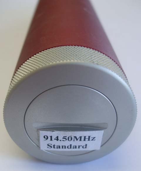
Click to zoom
Application Details
- Equipment Class
- DXX - Part 15 Low Power Communication Device Transmitter
- Date of Grant
- Oct 19, 2014
- Application Purpose
- Original Equipment
- Date of Application
- Oct 19, 2014
- Equipment Note
- Short Range Transmitter
- Frequency Range
- 914.50000000 - 914.50000000
- Company
- Electrix Pty Ltd
- Country
- Australia
Documents & Files
Document Text
Text extracted from the exhibit documents filed with the FCC. Open a document above to read the original.
Users Manual
SB800/SB800U Ultrasonic Test Unit Operating Guide and Technical Information Please read this documentation before operating the SB800/SB800U Model No: SB800/SB800U Display Unit Serial No: Transmitter Probe Serial No: Receiver Probe Serial No: Quality Assurance Completed: Manual code: SB800INST3.1 Manual date: October 2014 Copyright© 2014 Woodsonix Limited SB800/SB800U Ultrasonic Test Unit Please check your package contents include: Operating Guide and Technical Information manual. Carry case containing transmitter probe, receiver probe and display unit. 1. Overview The SB800 is an ultrasonic test unit for use in making single pulse transmission time measurements in solid samples. The SB800 consists of three units: A transmitter probe (Red) A receiver probe (Blue) A display module (Silver) where readings are given in microseconds (μS) The unit operates by the transmitter probe producing an acoustic pulse at the tip of the probe and timing the subsequent interval until the pulse is successfully detected at the receiver probe. The transmission time will depend on the propagation within the sample and the thickness of the sample. The three units are switched on automatically when they are removed from the carry case. Note that the carry case contains magnetic material that may damage sensitive items, such as credit card strips, that are held in close proximity. 2. High-Voltage Warning! The transmitter probe has a high voltage present internally. This can cause a painful electric shock, and for this reason we recommend that you return faulty units to Woodsonix or its authorized dealers for servicing. The unit should not be operated with the probes immersed in any liquid. 3. Intellectual Property All intellectual property relating to the concept, design and implementation of the SB800 hardware and software belongs to Woodsonix Limited. Copyright, patent, and other infringements will be dealt with aggressively. 4. Operating Instructions The units are switched on automatically by removing them from their carry case. In order to prolong battery life, the units should be turned off (by replacing the base unit and probes in the case) whenever they are not in use. 4.1 Unit Identification The probes are colour coded. The transmitter probe has a red coloured body and the receiver probe is blue. Readings are shown on the display unit's screen. A sample screenshot is shown in figure 1. Figure 1. Display-unit screenshot 4.2 Displayed Measurement With the probe tips firmly applied to a solid sample, a reading of the transmission time in microseconds should be displayed. If no measurement is displayed this can indicate that the attenuation in the sample is too great, the transmission time is greater than 2000 microseconds, or the unit is faulty (check batteries). Figure 2 shows the display location of the reading. Figure 2. Reading portion of the display With the display unit turned on and the probes held apart, the screen should show: ‘----’ instead of a reading, indicating that no measurement is being made. If the display shows a reading in this situation this may indicate a faulty/damaged probe or low battery voltage. 4.3 Previous Reading The number in the top right of the display-module screen represents the most recent good reading. Its display position is shown in figure 3. Figure 3. Previous reading portion of the display 4.4 Battery-Level Indicators There are three battery-level indicators on the right of the display-module screen as shown in figure 4. See section 6 for more section for more information on battery replacement. Figure 4. Battery life indicator portion of the display The unit is carefully calibrated after manufacture, and is rechecked during the quality assurance stage. In order to test this calibration, and the correct operation of the unit, press the two probe tips together; a reading of ‘0’ should be displayed. 5. Serial Number Identification Each SB800 component is uniquely identified with a serial number. In addition to a physical number, an electronic serial number is stored in each component and these are shown on the screen when the display module is turned on. Note that the displayed probe serial numbers are those in use when the display unit was turned off. Therefore, the first time replacement probes are used, the displayed serial numbers will not match the actual probes. 6. Battery Replacement Each battery indicator is shown as a solid rectangle when the batteries are fully charged. An empty, or near empty, rectangle indicates that the batteries in the associated unit should be changed. The letter beside each battery tells which unit the battery reading is for: R (Red) for the transmitter probe B (Blue) for the receiver probe S (Silver) for the display module The unit will continue to give accurate timing measurements when the battery voltage is low, as long as the transmit pulses continue, but the sensitivity will be reduced. Ensure that the batteries are inserted correctly and never mix old batteries with new ones. For maximum battery life, alkaline batteries should be used. 6.1 Replacement of Probe Batteries Unscrew the cap at the rear of the probe by turning it anticlockwise. The battery holder can be slid out and the batteries changed. Ensure that the terminals on the end of the battery holder point towards the probe tip when it is re-inserted, and that they line up the metal contacts in the probe. Figure 5 shows the probes with unscrewed caps. 6.2 Replacement of Display-Unit Batteries Remove the four screws on the rear of the display unit to open up the battery cavity. Replace the batteries in the battery holder. Do not remove the plate that covers the front of the display unit, as it seals the electronic and microprocessor components from environmental damage. Figure 5 shows the display unit with the battery cavity visible. Figure 5. Probes and display unit opened for battery replacement 7. Care of the Unit The SB800 is a sensitive piece of test equ…
Text truncated - open the document above for the full version.
Cover Letter(s)
Woodsonix Ltd PO Box 491 Dury Auckland 2578 NEW ZEALAND To Federal Communications Commission 9 th September 2014 To whom it may concern CONFIDENTIALITY REQUEST – FCC ID: 2AC4P-WSSB800TX Reference rule sections 0.457 (d) (ii) and pursuant to rule section 0.459 (a) confidentiality is requested as follows. Specific Information: Schematic diagrams, Part lists, Block Diagram, Operational Description This information contains trade secret information which is not routinely made available to the public or to our competitors. Disclosure of this information could result in an unfair advantage to our competitors. It should be treated as confidential for the duration of the Grant of Equipment Authorisation. Yours sincerely Peter Robinson Director
External Photos
____________________________________________________________________________________________________________________________________________________________________________ Page 16 of 19 Test Report No 140724.2 12th August 2014 This report may not be reproduced except in full. 10. PHOTOGRAPHS External photos
Internal Photos
Internal photos ‐ Red Probe
Test Report
____________________________________________________________________________________________________________________________________________________________________________ Page 1 of 19 Test Report No 140724.2 12th August 2014 This report may not be reproduced except in full. EMC Technologies (NZ) Ltd PO Box 68-307 Newton, Auckland 1145 New Zealand Phone 09 360 0862 Fax 09 360 0861 E-Mail Address: [email protected] Web Site: www.emctech.com.au TEST REPORT Woodsonix SB800 Wooden Pole Ultrasonic Transmitter (Red Probe) tested to the Code of Federal Regulations (CFR) 47 Part 15 – Radio Frequency Devices, Subpart C – Intentional Radiators Section 15.249 – Operation in the band 900 – 928 MHz for Woodsonix Ltd This Test Report is issued with the authority of: ________________________________________ Andrew Cutler - General Manager ____________________________________________________________________________________________________________________________________________________________________________ Page 2 of 19 Test Report No 140724.2 12th August 2014 This report may not be reproduced except in full. Table of Contents 1. STATEMENT OF COMPLIANCE 3 2. RESULTS SUMMARY 3 3. CLIENT INFORMATION 3 4. DESCRIPTION OF TEST SAMPLE 4 5. EQUIPMENT PARAMETERS 5 6. ATTESTATION 6 7. TEST RESULTS 7 8. TEST EQUIPMENT USED 15 9. ACCREDITATIONS 15 10. PHOTOGRAPHS 16 ____________________________________________________________________________________________________________________________________________________________________________ Page 3 of 19 Test Report No 140724.2 12th August 2014 This report may not be reproduced except in full. 1. STATEMENT OF COMPLIANCE The Woodsonix SB800 Wooden Pole Ultrasonic Transmitter (Red Probe) complies with 47 CFR Part 15 and in particular Sections, 15.205, 15.207, 15.209, 15.215 and 15.249 as detailed below when tested in accordance with ANSI C63.4 – 2003. 2. RESULTS SUMMARY The results of testing carried out in August 2014 are detailed below. Clause Description Result 15.201 Equipment authorisation requirement Applied 15.203 Antenna requirement Complies 15.204 External power amplifiers Not applicable 15.205 Operation in restricted bands Complies 15.207 Conducted emissions Not applicable 15.209 Radiated emissions See below 15.215 Additional provisions Complies 15.249 (a) Field strength of fundamental Complies 15.249 (a) Field strength of harmonics Complies 15.249 (b) Fixed, point to point operations Not applicable 15.249 (c) 3 metre measurement distance Noted 15.249 (d) Spurious emission levels except harmonics Complies 15.249 (e) Detectors above 1000 MHz Noted 15.249 (f) Reference to section 15.37(d) Noted 3. CLIENT INFORMATION Company Name Woodsonix Ltd Address PO Box 491 Drury City Auckland 2247 Country New Zealand Contact Mr Brian Mitchell ____________________________________________________________________________________________________________________________________________________________________________ Page 4 of 19 Test Report No 140724.2 12th August 2014 This report may not be reproduced except in full. 4. DESCRIPTION OF TEST SAMPLE Brand Name Woodsonix Model Number SB800 Product Wooden Pole Ultrasonic Transmitter (Red Probe) Manufacturer Woodsonix Ltd Country of Origin New Zealand Serial Number SB8000124 + SB8000112 FCC ID 2AC4P-WSSB800TX Product Description This system consists of three items as detailed below: - Ultrasonic transmitter (red probe) that transmits an ultrasonic pulse and then transmits a burst of RF on 914.500 MHz to indicate that a pulse has been transmitted. - Ultrasonic receiver (blue probe) that receives an ultrasonic pulse and then transmits a burst of RF on 914.500 MHz to indicate that a pulse has been received. - A receiver unit that operates on 914500 MHz which then combines both transmissions and makes a measurement which is then displayed on the LCD screen. This report describes the measurements made on the Ultrasonic transmitter (Red Probe). ____________________________________________________________________________________________________________________________________________________________________________ Page 5 of 19 Test Report No 140724.2 12th August 2014 This report may not be reproduced except in full. 5. EQUIPMENT PARAMETERS The 900 MHz transmitter in this device has the following RF specifications: FCC Band: 900 MHz – 928 MHz Test Frequency: 914.500 MHz Operating Frequencies: 914.500 MHz Rated Power: 10.0 uW (-20.0 dBm) Modulation Type: FSK Data Antenna Type: Internal Whip Power Supply: Internal batteries Clock frequencies 6 MHz ____________________________________________________________________________________________________________________________________________________________________________ Page 6 of 19 Test Report No 140724.2 12th August 2014 This report may not be reproduced except in full. 6. ATTESTATION This report describes the tests and measurements performed for the purpose of determining compliance with the specification with the following conditions: The client selected the test sample. The report relates only to the sample tested. This report contains no corrections. Measurement uncertainties with statistical confidence intervals of 95% are shown below test results. Both Class A and Class B uncertainties have been accounted for, as well as influence uncertainties where appropriate. All compliance statements have been made with respect of the specification limit with no reference to the measurement uncertainty. In addition this equipment has been tested in accordance with the requirements contained in the appropriate Commission regulations. To the best of my knowledge, these tests were performed using measurement procedures that are consistent with industry or Commission standards and demonstrate that the equipment complies with the appropriate standards. I further certify that the necessary measurements were made by EMC Technologies NZ Ltd, 47 MacKelvie Street, Grey Lynn, Auckland, New Zealand. Andrew C…
Text truncated - open the document above for the full version.
Test Setup Photos
____________________________________________________________________________________________________________________________________________________________________________ Page 17 of 19 Test Report No 140724.2 12th August 2014 This report may not be reproduced except in full. Test set up photos - X Plane ____________________________________________________________________________________________________________________________________________________________________________ Page 18 of 19 Test Report No 140724.2 12th August 2014 This report may not be reproduced except in full. Y plane ____________________________________________________________________________________________________________________________________________________________________________ Page 19 of 19 Test Report No 140724.2 12th August 2014 This report may not be reproduced except in full. Z plane
Contact Information
Applicant
Peter Bell(Business Unit Manager)
Test Firm
EMC Technologies NZ Ltd.Andrew Cutler
Technical Specifications
| # | Rule Parts | Frequency Range | Power Output |
|---|---|---|---|
| 1 | 15C | 914.5 MHz - 914.5 MHz | - |
Other Applications from Electrix Pty Ltd
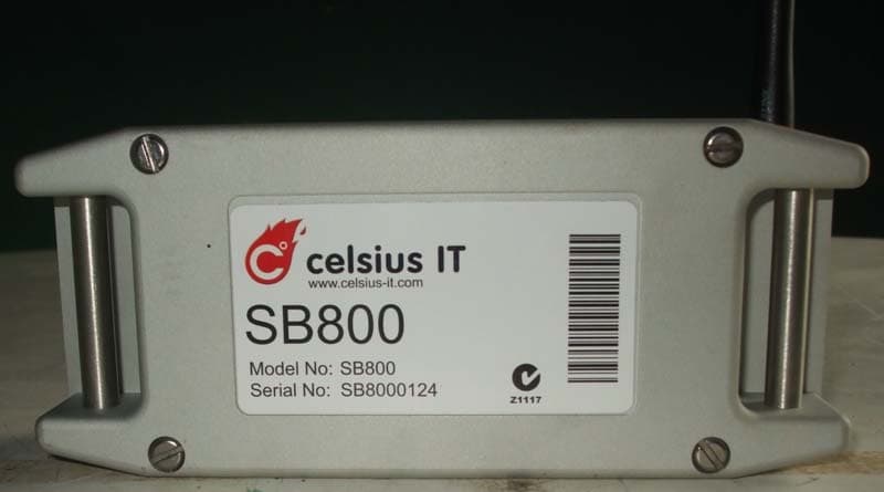
2AC4P-WSSB800
Oct 19, 2014Display Receiver
Equipment Class
CYY - Communications Receiver used w/Pt 15 Transmitter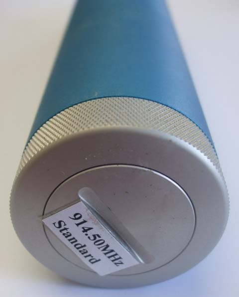
2AC4P-WSSB800RX
Oct 19, 2014Short Range Transmitter
Equipment Class
DXX - Part 15 Low Power Communication Device Transmitter