2AC52R73GRemote Terminal Unit for wireless monitoring system
Creowave Oy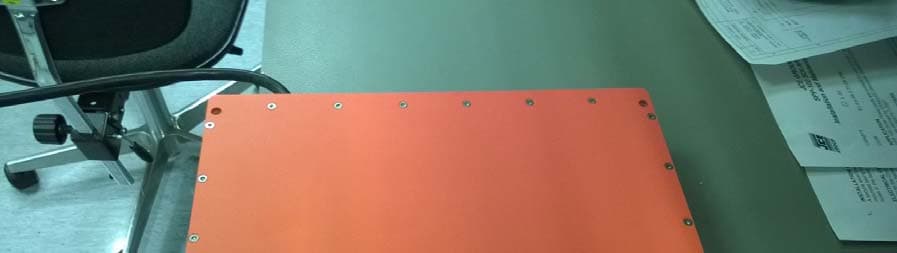
Click to zoom
Application Details
- Equipment Class
- DTS - Digital Transmission System
- Date of Grant
- Apr 23, 2015
- Application Purpose
- Original Equipment
- Date of Application
- Apr 23, 2015
- Equipment Note
- Remote Terminal Unit for wireless monitoring system
- Frequency Range
- 2405.00000000 - 2480.00000000
- Company
- Creowave Oy
- Country
- Finland
Documents & Files
Document Text
Text extracted from the exhibit documents filed with the FCC. Open a document above to read the original.
Users Manual
C-site User Manual Version 1.1 Ex-CWTD-WRM-00009 Page 2 / 27 Ex-CWTD-WRM-00009 C-site User Manual Version 1.1 PRINTED – 13.3.2015 CREOWAVE OY | Creowave Oy, Yrttipellontie 10 H, 90230 Oulu, Finland | T: +358 10 8326 300 | www.creowave.com Version history Version Date Description Author Approver 1.0 23.2.2015 Approved version KL TVä 1.1 13.3.2015 IC certification numbers p. 9 TSo Page 3 / 27 Ex-CWTD-WRM-00009 C-site User Manual Version 1.1 PRINTED – 13.3.2015 CREOWAVE OY | Creowave Oy, Yrttipellontie 10 H, 90230 Oulu, Finland | T: +358 10 8326 300 | www.creowave.com Contents Contents .................................................................................................................................................. 3 1 Introduction ....................................................................................................................................... 4 1.1 C-site units at a glance .............................................................................................................4 1.1.1 C-site S7 .............................................................................................................................. 4 1.1.2 C-site R7 .............................................................................................................................. 7 2 Notes and wireless conditions .......................................................................................................... 9 2.1 All units (S7001, S7002, R7-001, R7-101) ...............................................................................9 2.2 C-site R7-001......................................................................................................................... 10 3 Getting started ................................................................................................................................ 12 3.1 Before R7 configuration ......................................................................................................... 13 3.2 R7 WLAN configuration ......................................................................................................... 15 3.3 R7 3G configuration ............................................................................................................... 18 4 Setting up the sensor network ........................................................................................................ 19 5 Troubleshooting .............................................................................................................................. 24 6 Maintenance ................................................................................................................................... 25 6.1 Security passwords ............................................................................................................... 26 7 Support ........................................................................................................................................... 27 Page 4 / 27 Ex-CWTD-WRM-00009 C-site User Manual Version 1.1 PRINTED – 13.3.2015 CREOWAVE OY | Creowave Oy, Yrttipellontie 10 H, 90230 Oulu, Finland | T: +358 10 8326 300 | www.creowave.com 1 Introduction This user manual describes the practices to take the C-site remote monitoring system into use. Also guidance on how to operate and maintain the system is given. C-site remote monitoring system consists of C-site S7 sensor units as well as C-site R7 remote terminal units. 1.1 C-site units at a glance 1.1.1 C-site S7 C-site S7 is the sensor unit of the C-site Remote monitoring system. It reads data from the transducers and transfers the data wirelessly to the C-site R7 units. C-site S7 has two different model options, C-site S7001 and C-site S7002. C-site S7001 is a sensor unit with integrated Keller pressure transducer. C-site S7002 is equipped with a connector that enables different type of sensors to be used with the sensor unit. Figure 1. C-site S7001 top view and back view. (Note! Batteries ordered and delivered separately) 1. Ex batteries 2. 2.4GHz antenna 3. Battery cap 1. Rotation adapter SW 27 mm 2. Rotation lock nut SW 36 mm Page 5 / 27 Ex-CWTD-WRM-00009 C-site User Manual Version 1.1 PRINTED – 13.3.2015 CREOWAVE OY | Creowave Oy, Yrttipellontie 10 H, 90230 Oulu, Finland | T: +358 10 8326 300 | www.creowave.com 1. Connector cap 2. Binder connector 1. Connector cap 2. Binder connector Figure 2. C-site S7002 top view and back view. (Note! Cables and transmitters for Binder connector ordered separately) 1. Ex batteries 2. 2.4GHz antenna 3. Battery cap 4. Binder connector Page 6 / 27 Ex-CWTD-WRM-00009 C-site User Manual Version 1.1 PRINTED – 13.3.2015 CREOWAVE OY | Creowave Oy, Yrttipellontie 10 H, 90230 Oulu, Finland | T: +358 10 8326 300 | www.creowave.com In normal operation, the screen shows the pressure (1), temperature (2), received signal strength (3) and battery levels (4 and 5). 1.1.1.1 C-site S7 screens This section describes the different screen views the S7 unit can display during operation. After power up, the S7 unit starts automatic scanning of available R7 units. Normally the scanning phase takes about 30 seconds. 1. Pressure 2. Temperature 3. Signal level 4. Battery level 5. Battery level In case the alarm sign is on, please check the alarm status and details from the alarm log on the R7 display. In case of a low battery level, please replace the batteries in safe area. Only batteries delivered by Creowave is permitted. Page 7 / 27 Ex-CWTD-WRM-00009 C-site User Manual Version 1.1 PRINTED – 13.3.2015 CREOWAVE OY | Creowave Oy, Yrttipellontie 10 H, 90230 Oulu, Finland | T: +358 10 8326 300 | www.creowave.com 1.1.2 C-site R7 C-site R7 is remote terminal unit of the C-site Remote monitoring system. C-site R7 collects data and information from multiple C-site S7 units and sends the information onwards to the system. C-site R7 has three different model options, C-site R7-001, R7-101 and R7-201. Only difference …
Text truncated - open the document above for the full version.
Cover Letter(s)
))) CREOWAVE Attention: Nadira Nechma, IntertekSemkoAbApplication Examiner Re: Cover Letter Applicant: Creowave Oy FCC ID: 2AC52R73G To whom it may concern, Cover Letter / Agency Letter We, Creowave Oy, hereby authorize Intertek Semko AB, Sweden, to act as agent in the preparation ofthis application, FCC ID: 2AC52R73G for equipment authorizationto the Federal Communications Commission. l certify that submitted Exhibits properly describe the device vvith FCC ID: 2AC52R73G This is to advise that we are in full compliance with the Anti-Drug Abuse Act. The applicant is not subject to a denial offederal benefits pursuant to Section 5301 of the Anti-Drug Act of 1988, 21 U.S.C. 862, and no party to the application is subject to a denial of federal benefits pursuant to that section. Sincerely, Teemu Vähäkangas Vice President Creowave Oy
Cover Letter(s)
0) CR60\VAVE Attention: Nadira Nechma, Intertek Semko AbApplication ExaminerRe: Request for confidentialityApplicant: Creowave Oy FCC ID: 2AC52R73G To whom it may concern,Permanent Confldentiality Request is hereby submitted by Creowave Oy to withhold permanently from public review certainportions of the application for equipment certification for the referenced FCC identifiers. This request for confidentiality is made pursuant to 47 CFR 0.457(d) and 0.459 of the FCC Rules. In particular, the following sections of the application are to be kept permanently confidential: • Schematics• Detailed Block diagrams• Detailed Operational/FunctionaI Description Rationale for request for confidentiality: Creowave Oy has invested considerable time and materials in research and development to produce the referenced product. Disclosure of the permanently confidential portions ofthis application to competitors would not only give them significant competitive advantages in developing similar products, but would also disclose successful implementation ofunpublished, leading edge technology developed by us. Sincerely, 1^ Teemu VähäkangasVice President Creowave Oy 1(1)
Cover Letter(s)
Q) CREOWAVE 11.02.2015Federal Communications Commission 74350aklandMillsRoadColumbia, MD 21046 Subject: Professional installationjustification To Whom lt May Concern: We, Creowave Oy, inform that the C-site R7 unit (FCC ID: 2AC52R73G, models R7-101 and R7-102) is intended to be installed only by a professional person. The device is not sold to the general public.The installation must be controlled by Creowave Oy or a dealer approved by Creowave Oy. Installation requires special training to make sure that the network parameters will be properly configured. Access to the parameters is password protected.The unit, in conjunction with C-site S7, is used for data transmission located in oil and gas fields. Only the antenna types listed in the User Manual is allowed to be used. Creowave Oy will supply theantenna as part of the unit. Sincerely, ^ '^ Teemu Vähäkangas Vice President Creowave Oy
External Photos
External Photos Model: R73G External Photos Model: R73G
External Photos
External Photos Model: R73G 1(2) External Photos Model: R73G 2(2)
ID Label/Location Info
Model: R73G
ID Label/Location Info
34 Replace capacitors 10->4.7pF when WLAN module is used 35 APBOCNDMELFK HIGJFKELDMCNBOAP 9 9 8 8 10 10 7 7 11 11 6 6 12 12 5 5 13 13 4 4 14 14 3 3 15 15 2 2 16 16 1 1 DESIGNED BY JLa DATE CHECKED BY TVä DATE DRAWN BY JLa DATE This drawing is our property. It can't be reproduced or communicated without our written agreement. SCALE 1:1WEIGHT(kg)~5SHEET1/1 SIZE A0 DRAWING NUMBER Ex_530015 REV 1.7 DRAWING TITLE CWEx-RTU Assembly REVDATEDESCRIPTIONINIT 1.1 14.3.2013 M6x12->M6x16, quantity 2->3 pcs and o-rings added 24 Encapsulation silicone updated JLa 1.2 15.3.2013 N-connector changed JLa 26.6.2014 Cable glands updated, mechanics updated, torque specifications, label etc. JLa 1.3 1.4 2.7.2014 Label revision updated JLa 1.5 13.7.2014 Label modified JLa 1.6 1.8.2014 Label revision marking removed JLa 1.7 GSM label added, Frame assembly rev correction Capri Gland number update JLa Bill of Material: Ex_530015 NumberPart NumberDefinitionRevisionQuantityComment 1Ex_530022CWEx-RTU PCB assembly1* 2Ex_530047CWEx-RTU Frame Assembly Painted1.21* 3Ex_530048CWEx-RTU Bottom Plate Painted1.11* 4Ex_530049CWEx-RTU Connector Cover Painting1.21* 51.199.2000.50Hummel V-Ms-VMQ-Ex M20x1.51* 61.199.1600.50Hummel V-Ms-VMQ-Ex M16x1.50...4* according to product configuration 7CAP846504V1 (CAP846504)Capri ADE 4F M16 No 6 0...4* according to product configuration 8CAP221645Cooper Crouse-Hinds M16 Fiber Washer0...4* according to product configuration 91.640.1611.30HSK-M-Ex M16x1.50...4* according to product configuration 10TOM100Motorola Tetra Modem0(1)according to product configuration 11DPP-CT6448 DemmelLCD Panel1 12FJ-20-D-08.00-4Samtec FPC Flex Cable jumper1 13U.FL-2LP-088K1T-A-(200)Hirose RF cable assembly dia. 1.37mm length 200mm1 14PH8-PCinterion0(1)according to product configuration 15WLg-LINK-OEM-TTLAcksys Wifi Module0(1)according to product configuration 1616114-03-D50-ORA-NPS(-SPL)Environmental Seal Double-D Gaskets532mm* 1716114-03-D50-ORA-NPS(-SPL)Environmental Seal Double-D Gaskets914mm* 18OR 5,82 X 1,2 NBR70O-ring3* 19CR2450Energizer 3.0V (Li/MnO2)1* 20DIN965 T30 A2 M6x16Countersunk screw3 21DIN 7985 TX10 A2 M3 x 6Pan Head Machine Screw32 (26)32 pcs if WLg-LINK-OEM-TTL installed 22DIN965 A2 TX10 M3x8Countersunk Machine Screw23 2305.03.103Ettinger Hex-Standoff M3x102 (0)2 pcs if WLg-LINK-OEM-TTL installed 24DIN 125A ZN M3/3.2M3 Washer3 (0)3 pcs if WLg-LINK-OEM-TTL installed 25DIN 7985 A2 M4x10Pan Head Machine Screw1 26DIN 125A A2 M4/4.3M4 Washer1 27QSil 550 AACC Silicones potting component A0,95 kg* 28QSil 550 BACC Silicones potting component B0,95 kg* 29202102-10AMPHENOL CONNEX, N MALE CAP, NO CHAIN4 30Ex_530057CWEx-R7 Ex Label1* 31ELASTOSIL N9111 WHITEWACKER SILICONES~1.5 ml* 32Primer No 3 ACC Silicones Primer~10 ml*For frame and PCB priming before encapsulation 33Micro SD SDHC 32 GBMicroSD Card1For example "Kingston" 342500V 4.7pF Ceramic CapacitorCheck RTU PCB documentation for approved types0 (2)2 pcs if WLg-LINK-OEM-TTL installed 35Ex_530064CWEx-R7 GSM Label1(0)Installed when PH8-P 3G Modem used *Safety component, may not be altered without approval of the Certification Body 10.10.2014 10.10.2014 10.10.2014 10.10.2014 47 161.75197.75 240.5 103 65590125235284 198 219 +0.5 0 15 24.4 (~ ) 287 (~ ) 167.5 6.5 4X Front view Scale: 1:1 GSM/TETRA/WLAN Antenna 3X 2.4GHz Antenna POWER+12V AFU INTERFACE RS-485/1RS-485/2 ETHERNET A A 28 14.15 70 ( ) 42 ±2 3.5 ±1 33 ( ) 40() 19() 19.5() 10 ±2 21 ±2 15 25 Left view Scale: 1:1 SIM 30 Make sure label area is free of greases before installation 35 290 +0.5 0 294.4~ 45 +1 0 Bottom view Scale: 1:1 Isometric view Scale: 1:1 7 1 8 5 6 10 11 13 14 15 16 17 20 21 23 24 This end connected to: PH8-P GSM/UMTS antenna connector OR TOM100 antenna connector OR WLg-LINK-OEM-TTL main antenna connector according to product configuration 21 22 18 2 3 4 9 21 2526 CUT AND BOND GASKET ACCORDING TO CWAI-WRM-00002 Assembly Instructions R7 USE WACKER SILICONES ELASTOSIL N9111 WHITE CUT AND BOND GASKET ACCORDING TO CWAI-WRM-00002 Assembly Instructions R7 USE WACKER SILICONES ELASTOSIL N9111 WHITE 29 30 Tightening torque 3 Nm Optional gland for Capri ADE 4F M16 No 6 Body tightening torque 6.25 Nm Do not tighten dome nut! Tightening torque 0.5 Nm (non-critical) Tightening torque 0.5 Nm Tightening torque 1 Nm Remove leds (5 pcs) Replace serrated washer under standoff Tightening torque 0.5 Nm SEAL DISPLAY FRAME ACCORDING TO CWAI-WRM-00002 Assembly Instructions R7 USE WACKER SILICONES ELASTOSIL N9111 WHITE Hand tighten Plug empty M16x1.5 holes with blanking plug. Tightening torque 6.3 Nm Tightening torque 6.3 Nm Body tightening torque 12.5 Nm Do not tighten internal or external cap 32 Apply primer to the PCB before assembly according to CWAI-WRM-00002 Assembly Instructions R7 Apply primer to the frame before assembly according to work instructions Seal SIM card pocket borders and connector department with Elastosil N9111 White according to work instructions 19 33 12 12 0 -2 25 Section view A-A Scale: 1:1 2728 Detailed encapsulation document CWEx-RTU Encapsulation Ex_530062
ID Label/Location Info
MATERIAL SPECIFICATION 7818EH 3M TT5 MS PET 75-310E-90WG Facestock: 80 μm Matte Silver polyester Adhesive: 20 μm #310 E Acrylic Liner: 77 μm, 90 g/m² White Densified Glassine AD BCAD 3 3 2 2 4 4 1 1 DESIGNED BY JLa DATE CHECKED BYDATE DRAWN BY JLa DATE This drawing is our property. It can't be reproduced or communicated without our written agreement. SCALE 1:1WEIGHT(kg)SHEET SIZEDRAWING NUMBERREV 1.0 DRAWING TITLE Ex_530067 CWEx-R7 FCC WLAN Label 0,00 A4 1/1 16.3.2015 16.3.2015 16.3.2015 TVä Front view Scale: 1:1 This device complies with part 15 of the FCC Rules. Operation is subject to the following two conditions: (1) This device may not cause harmful interference, and (2) this device must accept any interference received, including interference that may cause undesired operation. 25 50
ID Label/Location Info
Label Model: R73G
Internal Photos
Internal Photos Model: R73G Internal Photos Model: R73G Internal Photos Model: R73G Internal Photos Model: R73G Internal Photos Model: R73G
Internal Photos
Internal Photos Model: R73G 1(2) Internal Photos Model: R73G 2(2)
RF Exposure Info
Reference No. 1405863STO-004_MPE www.intertek-etlsemko.com This Statement of Compliance is for the exclusive use of Intertek's client and is provided pursuant to the agreement between Intertek and its Client. Intertek's responsibility and liability are limited to the terms and conditions of the agreement. Intertek assumes no liability to any party, other than to the Client in accordance with the agreement, for any loss, expense or damage occasioned by the use of this Statement. Only the Client is authorized to permit copying or distribution of this Statement of Compliance. Any use of the Intertek name or one of its marks for the sale or advertisement of the tested material, product or service must first be approved in writing by Intertek. 1(2) STATEMENT ON EXPOSURE TO ELECTROMAGNETIC FIELDS EQUIPMENT Type of equipment: Remote terminal unit with 3G connectivity Brand name: Creowave Type / Model: R7-101, R7-102 Manufacturer: Creowave Oy By request of: Creowave Oy STANDARD 47 CFR §2.1091, 47 CFR §1.1307, 47 CFR §1.1310 RSS-102 Issue 5 CALCULATIONS Power density calculation is as follows: 2 4r EIRP S Manufacturer’s installation guide states that minimum distance between antennas and user is 50 cm. Highest Measured output power for ZigBee is 19.18 dBm. Antenna Gain 5 dBi S = (261,8 mW) / (4π*50cm 2 ) = 0.0083 mW / cm 2 For three ZigBee transmitter simultaneous operation S = 0.025 mW / cm 2 Highest measured output power for GSM /3G is GSM and EDGE modes 824.2 - 848.8 MHz 31.92 dBm 1850.4 - 1909.8 MHz 27.21 dBm Reference No. 1405863STO-004_MPE www.intertek-etlsemko.com This Statement of Compliance is for the exclusive use of Intertek's client and is provided pursuant to the agreement between Intertek and its Client. Intertek's responsibility and liability are limited to the terms and conditions of the agreement. Intertek assumes no liability to any party, other than to the Client in accordance with the agreement, for any loss, expense or damage occasioned by the use of this Statement. Only the Client is authorized to permit copying or distribution of this Statement of Compliance. Any use of the Intertek name or one of its marks for the sale or advertisement of the tested material, product or service must first be approved in writing by Intertek. 2(2) WCDMA mode 826.4 - 846.6 MHz 21.92dBm 1852.4 - 1907.6 MHz 20.74dBm Antenna Gain 4 dBi @ 850 MHz 5 dBi @ 1900 MHz Power density: S GSM 850 = (3908.4 mW) / (4π*50cm 2 ) = 0.1244mW / cm 2 S GSM 1900 = (1663.4 mW) / (4π*50cm 2 ) =0.0529 mW / cm 2 S WCDMA 850 = (390.8mW) / (4π*50cm 2 ) = 0.0124 mW / cm 2 S WCDMA 1900 = (375.0mW) / (4π*50cm 2 ) = 0.0119 mW / cm 2 Limit for General Population/Uncontrolled Exposure according to §1.1310 for power density between 1500 – 100 000 MHz is 1mW / cm 2 and f(MHz)/1500 mW / cm 2 between 300 – 1500 MHz. RSS-102 table 4 field strength limit for general public environment between 300 – 6000 MHz is 0.02619 ƒ(MHz) 0.6834 . Limits CFR 47 §1.1310 Limit 1 at 824.2 MHz = 0.549 mW / cm 2 Limit 2 at 1900 and 2450 MHz is = 1mW / cm 2 Limits RSS-102 table 4 Limit 1 at 824.2 MHZ = 5.49 W / m 2 Limit 2 at 1900 MHz = 4.47 W / m 2 Limit 3 2450 is = 5.42 W / m 2 Simultaneous transmission conditions: MPE 1 /limit 1 +MPE 2 / limit 2 +MPE n / limit n < 1 3 x ZigBee + GSM 850 = 3 x 0.0083/1 + 0.1244/0.549 = 0.251 = 3 x (0.083/5.42) + 1.244/5.49 = 0.273 3 x ZigBee + GSM 1900 = 3 x 0.0083/1 + 0.0529/1 = 0.078 = 3 x (0.083/5.42) + 0.529/4.47 = 0.164 EUT complies without testing. Intertek Semko AB, Radio& EMC Date of issue: 2015-03-30 Issued by: Matti Virkki
Test Report
Test report no. 1405683STO-002 Ed. 3 Page 2 (55) Revision History Edition Date Description 1 2014-10-06 First release 2 2014-11-10 Correction on model names by customer’s request 3 2015-02-20 Model name and editorial corrections Test report no. 1405683STO-002 Ed. 3 Page 3 (55) CONTENTS Page 1 CLIENT INFORMATION .................................................................................................................... 5 2 EQUIPMENT UNDER TEST (EUT) .................................................................................................. 5 2.1 IDENTIFICATION OF THE EUT ACCORDING TO THE MANUFACTURER/CLIENT DECLARATION......... 5 2.2 ADDITIONAL HARDWARE INFORMATION ABOUT THE EUT .............................................................. 6 2.3 ADDITIONAL INFORMATION ABOUT THE EUT ................................................................................. 6 2.4 PERIPHERAL EQUIPMENT ............................................................................................................... 6 2.5 TEST SIGNALS ................................................................................................................................ 6 2.6 MODIFICATION DURING THE TESTS ................................................................................................ 6 3 TEST SPECIFICATIONS ................................................................................................................... 7 3.1 STANDARDS ................................................................................................................................... 7 3.2 ADDITIONS, DEVIATIONS AND EXCLUSIONS FROM STANDARDS AND ACCREDITATION .................. 7 3.3 TEST SITE ....................................................................................................................................... 7 3.4 TEST SET-UP .................................................................................................................................. 7 3.5 TEST CONDITIONS .......................................................................................................................... 8 4 TEST SUMMARY ................................................................................................................................ 9 5 RADIATED EMISSIONS MEASUREMENTS FROM 30 MHZ TO 1000MHZ ...........................10 1.1 REQUIREMENT ..............................................................................................................................10 5.1 TEST SETUP DETAILS ....................................................................................................................10 5.2 TEST DATA .....................................................................................................................................11 5.3 TEST EQUIPMENT ..........................................................................................................................14 6 RADIATED EMISSIONS MEASUREMENTS ABOVE 1 GHZ ....................................................15 6.1 REQUIREMENT ..............................................................................................................................15 6.2 TEST SETUP DETAILS ....................................................................................................................15 6.3 TEST DATA .....................................................................................................................................16 6.4 TEST EQUIPMENT ..........................................................................................................................22 7 OCCUPIED BANDWIDTH ................................................................................................................23 7.1 REQUIREMENT ..............................................................................................................................23 7.2 TEST SET-UP .................................................................................................................................23 7.3 TEST DATA .....................................................................................................................................23 7.4 TEST EQUIPMENT ..........................................................................................................................25 8 CONDUCTED PEAK OUTPUT POWER .......................................................................................26 8.1 REQUIREMENT ..............................................................................................................................26 8.2 TEST SET-UP .................................................................................................................................26 8.3 TEST DATA .....................................................................................................................................26 8.4 TEST EQUIPMENT ..........................................................................................................................31 9 PEAK POWER SPECTRAL DENSITY...........................................................................................32 9.1 REQUIREMENT ..............................................................................................................................32 9.2 TEST SET-UP .................................................................................................................................32 9.3 TEST DATA .....................................................................................................................................33 9.4 TEST EQUIPMENT ..........................................................................................................................36 10 TRANSMITTER DWELL TIME AND DUTY CYCLE AVERAGING FACTOR .....................37 10.1 REQUIREMENT ............................................................................................................................…
Text truncated - open the document above for the full version.
Test Setup Photos
Test setup photos Model: R73G 1(2) Radiated emission 30 MHz – 1 GHz Radiated emission 1 – 18 GHz Test setup photos Model: R73G 2(2) Radiated emission 18-26 GHz preliminary sweep
Contact Information
Applicant
Teemu Vahakangas
Technical Contact
Non-Technical Contact
Creowave OyTaisto Soikkeli
[email protected]0504475
Test Firm
Intertek Semko ABPar Iggstrom
[email protected]+46708750026
Technical Specifications
| # | Rule Parts | Frequency Range | Power Output |
|---|---|---|---|
| 1 | 15C | 2.40 GHz - 2.48 GHz | 83.00 mW |
Other Applications from Creowave Oy
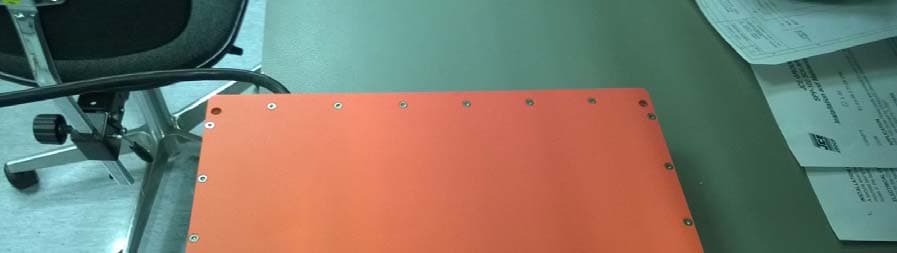
2AC52R7WLAN
Apr 26, 2015Remote Terminal Unit for wireless monitoring system
Equipment Class
NII - Unlicensed National Information Infrastructure TX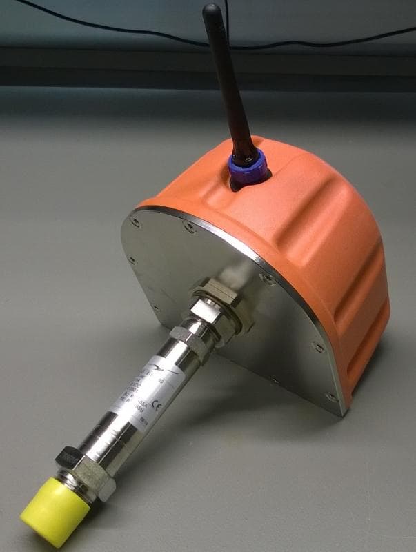
2AC52S7
Mar 26, 2015Low power wireless transceiver for remote monitoring system
Equipment Class
DTS - Digital Transmission System