2AC5T-SC-HUB-01Hub
Scout Security Inc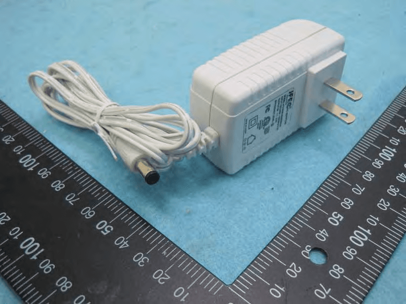
Click to zoom
Application Details
- Equipment Class
- DTS - Digital Transmission System
- Date of Grant
- Dec 29, 2014
- Application Purpose
- Original Equipment
- Date of Application
- Dec 28, 2014
- Equipment Note
- Hub
- Frequency Range
- 2405.00000000 - 2475.00000000
- Company
- Scout Security Inc
- Country
- United States
Documents & Files
Document Text
Text extracted from the exhibit documents filed with the FCC. Open a document above to read the original.
Users Manual
scout installation guide hello! welcome to scout. Scout is a do-it-yourself installation - no tools required. Install Scout from your smartphone or tablet for real- time feedback and interactive instructions. visit scoutalarm. com/install on your mobile phone or tablet recommended installation: alternate installation: follow along with this paper-based installation guide and your computer at scoutalarm. com/install overview of installation 1 2 3 4 The installation process should tak e 30 minutes or less for the average system. Here’s what to expect: register your system install and test devices choose a monitoring option set modes and permissions Before you tak e anything out of the box, note that the box your system shipped in doubles as a carrier. Take it with you around the house as you install so that you can receive real-time feedback from the sensors and save time. unboxing your system what’s in the box A t minimum, you should have received one Scout hub and one Scout sensor. Please confirm that you received the items pictured below and the contents of your box match the order that you placed. or 5 register login and register If you’re not using your phone or tablet to install Scout, you’ll need to visit www .scoutalarm.com and click “register” in the top right hand corner. Fill out the form on screen to create your account and register your system. Once you’ve completed these steps, you’ll be ready to install the Scout hub. register If you have questions or need help at any point during the installation: have questions ? Live chat with customer support on our website at scoutalarm. com E-mail [email protected] Visit our troubleshooting guide at support.scoutalarm.com 9 hub The hub is the communication center of Scout and essential to your system. The hub has a 100 ft. range . The hub box includes: The hub, a power cord and an ethernet cord. device: scout hub step one: power up L ocate a power outlet close to your router and plug the power cord into the hub and the wall. A light on the hub will turn on to indicate that it has been powered. step two: connect internet Plug the provided ethernet cord into your router and then into the back of the hub . A light on the hub will indicate that the ethernet plug is connected correctly. If you do not have a router, click the question mark on screen or visit support.scoutalarm.com for instructions. step three: confirm connection As the hub connects, it will flash a variety of lights. A solid green light means you are connected to our server . If your Hub does not have a solid green light, please click the question mark on screen or visit support.scoutalarm.com. step four: enter install code A fter the hub is connected, input the installation code in the field provided. The code can be found on the large Quick Start Card you received in your shipment. installation code: S A0000 step five: pairing hub The hub will start pairing once you enter the installation code . This process may be instant, but can take up to 3 minutes. The bars on screen will switch from unfilled to filled. Once the green light has changed from flashing green to solid green, the hub has successfully paired. step six: finish install If the Hub ’s light is solid green light, confirm a successful pairing on screen by clicking “It’s solid, install devices!” If the green light isn’t solid, please click the question mark on screen or visit support.scoutalarm.com. Important Installation Notes: Only remove the battery pull tabs from one device at a time. Pulling multiple tabs at once may result in pairing the wrong device. battery pull tabs pull If you incorrectly mounted a sensor , slowly twist the device left and right to loosen the adhesive. Pulling a device straight off may damage the surface. removing a sensor Install the sensor closest to the hub first and work your way out. Scout sensors have a range of appro ximately 100 ft. sensor sequence 19 motion sensor The motion sensor detects motion inside your home. The motion sensor has a 20 ft. range and a 90 degree field of view. Be sure to pair this device from its desired location to ensure you are in range of the Scout mesh network. device: motion sensor step one: power on Hold the faceplate down and remove the battery pull tab to engage the battery . The motion sensor will immediately enter pairing mode to pair with the hub . It can take up to 3 minutes for the device to pair to the hub. The bars on screen will switch from unfilled to filled when paired. step two: placement The motion sensor can be mounted in a corner , stand freely on a shelf or be hung on a screw. It should be 5-6 ft. off of the ground, regardless. Corner Shelf Flat 5-6 ft. step three: prep device If the unit is freestanding on a shelf , you can bypass this step. If you want to adhere the motion sensor, flip the motion sensor over and remove the adhesive from the appropriate pads. Place it in your desired location, in range. step four: name sensor Name your motion sensor something unique and click Submit. R epeat steps 1-4 if you have multiple motion sensors. If you have no more devices, you are done installing. name sensor ... 25 door panel The door panel monitors door activity and allows you to arm and disarm the system. It must be placed inside your home. Pair this device from its desired location to ensure you are in range of the Scout mesh network. The door panel box includes: one large panel, one small panel, two RFID key FOBs and one RFID sticker. device: door panel step one: power on Hold the faceplate down and remove the battery pull tabs to engage the batteries. The door panel will immediately enter pairing mode to pair with the hub . It can take up to 3 minutes for the device to pair to the hub. The bars on screen will switch from unfilled to filled and the door panel will “chirp” once when paired. step two: positioning Before we adhere the door panel, test your device with the on-screen instructions to confirm you’re within range . You’ll wa…
Text truncated - open the document above for the full version.
Cover Letter(s)
Page No. : 3 Scout Security Inc. 2023 W Carroll Ave C-206 Chicago Illinois 60612 United States Tel: (440) 622-5886 / Fax: (440) 622-5886 Confidential Letter Date: 2014/9/25 Federal Communications Commission Office of Engineering and Technology Equipment Authorization Division 7345 Oakland Mills Road Columbia, Maryland 21046 Subject: Confidentiality Request for FCC ID:2AC5T-SC-HUB-01 Gentlemen: The form 731 and application have been electronically submitted and any attachments will be up loaded to your web site to be used in obtaining a grant of certification. Short-term Pursuant to DA 04-1705 of the Commission’s pubic notice, we request short-term confidential treatment for the following information until 180 days after the Grant Date of Equipment Authorization in order to ensure sensitive business information remains confidential until the actual marketing of the device: 1. External Photos 2. Internal Photos 3. Test Setup photos 4. User’s Manual Permanent Scout Security Inc. requests that the material in the following files be withheld from public disclosure in accordance with Section 0.457 of the Commission’s Rules, 47 C.F.R. 0.459, following grant of the application. 1. Block Diagram 2. Circuit Diagram 3. Operational Description Should you require any further information, please contact the undersigned. Thank you for your consideration in this matter. Sincerely, Applicant’s company name : Scout Security Inc. Applicant’s company address : 2023 W Carroll Ave C-206 Chicago Illinois 60612 United States Signature : Name : Dave Shapiro E-Mail : [email protected] Tel. : (440) 622-5886
Cover Letter(s)
Page No. : 2 Scout Security Inc. 2023 W Carroll Ave C-206 Chicago Illinois 60612 United States Tel: (440) 622-5886 / Fax: (440) 622-5886 Power of Attorney Date: 2014/9/25 Dear Sir, I hereby have entrusted the following person to be a proxy regarding application for Type Certification. Sporton International Inc. Address : No.8, Lane 724, Bo-ai St., Jhubei City, HsinChu County 302, Taiwan, R.O.C. Name : Leo Huang Job Title : Manager e-mail : [email protected] I am therefore responsible for the contents of the application. Brand name and model type of the specified radio equipment: Scout / SCHUB01 FCC ID: 2AC5T-SC-HUB-01 Product name: Hub FCC Grantee contact person information. Applicant’s company name : Scout Security Inc. Applicant’s company address : 2023 W Carroll Ave C-206 Chicago Illinois 60612 United States Signature : Name : Dave Shapiro E-Mail : [email protected] Tel. : (440) 622-5886
External Photos
Report No.: 491639 SPORTON International Inc. PAGE NUMBER : 1 OF 4 TEL : 886-3-327-3456 ISSUED DATE : Dec. 24, 2014 FAX : 886-3-327-0973 Photographs of EUT Report No.: 491639 SPORTON International Inc. PAGE NUMBER : 2 OF 4 TEL : 886-3-327-3456 ISSUED DATE : Dec. 24, 2014 FAX : 886-3-327-0973 Report No.: 491639 SPORTON International Inc. PAGE NUMBER : 3 OF 4 TEL : 886-3-327-3456 ISSUED DATE : Dec. 24, 2014 FAX : 886-3-327-0973 Adapter Brand Name: JFEC Model No.: JF015WR-0500250UH Report No.: 491639 SPORTON International Inc. PAGE NUMBER : 4 OF 4 TEL : 886-3-327-3456 ISSUED DATE : Dec. 24, 2014 FAX : 886-3-327-0973
ID Label/Location Info
“Midnight” Sticker “Walnut” Sticker M/N : SCHUB01 F C C ID : 2AC5T-SC-HUB-01 I C : 12325A-SCHUB01 Scout Security, Inc. 2014 Designed in Chicago Made in China “Arctic” sticker Contains TX FCC ID:XPYLISAU200 Contains TX IC : 8595A-LISAU200 M/N : SCHUB01 F C C ID : 2AC5T-SC-HUB-01 I C : 12325A-SCHUB01 Scout Security, Inc. 2014 Designed in Chicago Made in China Contains TX FCC ID:XPYLISAU200 Contains TX IC : 8595A-LISAU200 M/N : SCHUB01 F C C ID : 2AC5T-SC-HUB-01 I C : 12325A-SCHUB01 Scout Security, Inc. 2014 Designed in Chicago Made in China Contains TX FCC ID:XPYLISAU200 Contains TX IC : 8595A-LISAU200 Label Here
Internal Photos
Report No.: 491639 SPORTON International Inc. PAGE NUMBER : 1 OF 11 TEL : 886-3-327-3456 ISSUED DATE : Dec. 24, 2014 FAX : 886-3-327-0973 Photographs of EUT Report No.: 491639 SPORTON International Inc. PAGE NUMBER : 2 OF 11 TEL : 886-3-327-3456 ISSUED DATE : Dec. 24, 2014 FAX : 886-3-327-0973 Report No.: 491639 SPORTON International Inc. PAGE NUMBER : 3 OF 11 TEL : 886-3-327-3456 ISSUED DATE : Dec. 24, 2014 FAX : 886-3-327-0973 Report No.: 491639 SPORTON International Inc. PAGE NUMBER : 4 OF 11 TEL : 886-3-327-3456 ISSUED DATE : Dec. 24, 2014 FAX : 886-3-327-0973 Report No.: 491639 SPORTON International Inc. PAGE NUMBER : 5 OF 11 TEL : 886-3-327-3456 ISSUED DATE : Dec. 24, 2014 FAX : 886-3-327-0973 Report No.: 491639 SPORTON International Inc. PAGE NUMBER : 6 OF 11 TEL : 886-3-327-3456 ISSUED DATE : Dec. 24, 2014 FAX : 886-3-327-0973 Report No.: 491639 SPORTON International Inc. PAGE NUMBER : 7 OF 11 TEL : 886-3-327-3456 ISSUED DATE : Dec. 24, 2014 FAX : 886-3-327-0973 Report No.: 491639 SPORTON International Inc. PAGE NUMBER : 8 OF 11 TEL : 886-3-327-3456 ISSUED DATE : Dec. 24, 2014 FAX : 886-3-327-0973 Report No.: 491639 SPORTON International Inc. PAGE NUMBER : 9 OF 11 TEL : 886-3-327-3456 ISSUED DATE : Dec. 24, 2014 FAX : 886-3-327-0973 Zigbee Antenna Report No.: 491639 SPORTON International Inc. PAGE NUMBER : 10 OF 11 TEL : 886-3-327-3456 ISSUED DATE : Dec. 24, 2014 FAX : 886-3-327-0973 Report No.: 491639 SPORTON International Inc. PAGE NUMBER : 11 OF 11 TEL : 886-3-327-3456 ISSUED DATE : Dec. 24, 2014 FAX : 886-3-327-0973
RF Exposure Info
Report No.: FR491639 FCC ID: 2AC5T-SC-HUB-01 Page No. : B1 of B3 Appendix B. Maximum Permissible Exposure Report No.: FR491639 FCC ID: 2AC5T-SC-HUB-01 Page No. : B2 of B3 1. Maximum Permissible Exposure 1.1. Applicable Standard Systems operating under the provisions of this section shall be operated in a manner that ensures that the public is not exposed to radio frequency energy levels in excess limit for maximum permissible exposure. In accordance with 47 CFR FCC Part 2 Subpart J, section 2.1091 this device has been defined as a mobile device whereby a distance of 0.2 m normally can be maintained between the user and the device. (A) Limits for Occupational / Controlled Exposure Frequency Range (MHz) Electric Field Strength (E) (V/m) Magnetic Field Strength (H) (A/m) Power Density (S) (mW/ cm²) Averaging Time |E|²,|H|² or S (minutes) 0.3-3.0 614 1.63 (100)* 6 3.0-30 1842 / f 4.89 / f (900 / f)* 6 30-300 61.4 0.163 1.0 6 300-1500 F/300 6 1500-100,000 5 6 (B) Limits for General Population / Uncontrolled Exposure Frequency Range (MHz) Electric Field Strength (E) (V/m) Magnetic Field Strength (H) (A/m) Power Density (S) (mW/ cm²) Averaging Time |E|²,|H|² or S (minutes) 0.3-1.34 614 1.63 (100)* 30 1.34-30 824/f 2.19/f (180/f)* 30 30-300 27.5 0.073 0.2 30 300-1500 F/1500 30 1500-100,000 1.0 30 Note: f = frequency in MHz ; *Plane-wave equivalent power density 1.2. MPE Calculation Method E (V/m) = d GP30 Power Density: Pd (W/m²) = 377 2 E E = Electric field (V/m) P = Average RF output power (W) G = EUT Antenna numeric gain (numeric) d = Separation distance between radiator and human body (m) The formula can be changed to Pd = 2 377 30 d GP From the EUT RF output power, the minimum mobile separation distance, d=0.2m, as well as the gain of the used antenna, the RF power density can be obtained. Report No.: FR491639 FCC ID: 2AC5T-SC-HUB-01 Page No. : B3 of B3 1.3. Calculated Result and Limit Exposure Environment: General Population / Uncontrolled Exposure For Zigbee : Antenna Type : Dipole Antenna Conducted Power for IEEE 802.15.4 ZigBee: 0.68 dBm Average Output Power Distance (m) Antenna Gain (dBi) Antenna Gain (numeric) (dBm) (mW) Power Density (S) (mW/cm²) Limit of Power Density (S) (mW/cm²) Test Result 0.2 -2.50 0.5623 0.6800 1.1695 0.000131 1 Complies For 3G Module (FCC ID: XPYLISAU200): Frequency range: 850 MHz Antenna Type: Dipole Antenna (-0.13 dBi) Max Conducted Power: 23.15 dBm EIRP power (dBm) EIRP power (mW) Power Density (S) (mW/cm²) Limit of Power Density (S) (mW/cm²) 23.02 200.4472 0.039898 0.57 Frequency range: 1900 MHz Antenna Type: Dipole Antenna (-0.13 dBi) Max Conducted Power: 23.73 dBm EIRP power (dBm) EIRP power (mW) Power Density (S) (mW/cm²) Limit of Power Density (S) (mW/cm²) 23.60 229.0868 0.045598 1 Conclusion: Both of the Zigbee and 3G can transmit simultaneously, the formula of calculated the MPE is: CPD1 / LPD1 + CPD2 / LPD2 + ......etc. < 1 CPD = Calculation power density LPD = Limit of power density (1) Zigbee + 3G (850MHz) = 0.000131 / 1 + 0.039898 / 0.57 = 0.070127 (2) Zigbee + 3G (1900MHz) = 0.000131 / 1 + 0.045598 / 1 = 0.045729 Therefore, the worst-case situation is Zigbee + 3G (850MHz), which is less than “1”. This confirmed that the device comply with FCC 1.1310 MPE limit.
Test Report
Report No.: FR491639 FCC ID: 2AC5T-SC-HUB-01 Page No. : C1 of C3 Appendix C. Radiated Emission Co-location Report Report No.: FR491639 FCC ID: 2AC5T-SC-HUB-01 Page No. : C2 of C3 1. Results of Radiated Emissions for Co-located Temperature 23°C Humidity 62% Test Engineer Jax Chen Configurations Zigbee + 3G Horizontal Report No.: FR491639 FCC ID: 2AC5T-SC-HUB-01 Page No. : C3 of C3 Vertial
Test Report
SPORTON International Inc. No. 52, Hwa Ya 1st Rd., Hwa Ya Technology Park, Kwei-Shan Hsiang, Tao Yuan Hsien, Taiwan, R.O.C. Ph: 886-3-327-3456 / FAX: 886-3-327-0973 / www.sporton.com.tw Report Format Version: Rev. 01 FCC RADIO TEST REPORT Applicant’s company Scout Security Inc. Applicant Address 2023 W Carroll Ave C-206 Chicago Illinois 60612 United States FCC ID 2AC5T-SC-HUB-01 Manufacturer’s company Sysgration Ltd. Manufacturer Address 6F-2., No.1, Sec.1, Tiding Blvd., Neihu Dist., Taipei City 114 Taiwan Product Name Hub Brand Name Scout Model No. SCHUB01 Test Ru le 47 CFR FCC Part 15 Subpart C § 15.247 Test Freq. Range 2400~2483.5 MHz Received Date Sep. 16, 2014 Final Test Date Dec. 17, 2014 Submission Type Original Equipment Statement Test result included is only for the IEEE 802.15.4 ZigBee of the product. The test result in this report refers exclusively to the presented test model / sample. Without written approval of SPORTON International Inc., the test report shall not be reproduced except in full. The measurements and test results shown in this test report were made in accordance with the procedures and found in compliance with the limit given in ANSI C63.10-2013, 47 CFR FCC Part 15 Subpart C and KDB 558074 D01 v03r02. The test equipment used to perform the test is calibrated and traceable to NML/ROC. Report No.: FR491639 Report Format Version: Rev. 01 Page No. : i of ii FCC ID: 2AC5T-SC-HUB-01 Issued Date : Dec. 26, 2014 Table of Contents 1. CERTIFICATE OF COMPLIANCE.....................................................................................................................................1 2. SUMMARY OF THE TEST RESULT ..................................................................................................................................2 3. GENERAL INFORMATION .................................................................................................................................................3 3.1. Product Details ................................................................................................................................................................................................................. 3 3.2. Accessories....................................................................................................................................................................................................................... 3 3.3. Table for Filed Antenna ................................................................................................................................................................................................... 4 3.4. Table for Carrier Frequencies .......................................................................................................................................................................................... 4 3.5. Table for Test Modes ....................................................................................................................................................................................................... 5 3.6. Table for Testing Locations ............................................................................................................................................................................................. 5 3.7. Table for Supporting Units .............................................................................................................................................................................................. 6 3.8. Table for Parameters of Test Software Setting................................................................................................................................................................ 6 3.9. EUT Operation during Test ............................................................................................................................................................................................. 7 3.10. Duty Cycle ....................................................................................................................................................................................................................... 7 3.11. Test Configurations.......................................................................................................................................................................................................... 8 4. TEST RESULT ......................................................................................................................................................................11 4.1. AC Power Line Conducted Emissions Measurement ................................................................................................................................................... 11 4.2. Maximum Conducted Output Power Measurement ...................................................................................................................................................... 15 4.3. Power Spectral Density Measurement ........................................................................................................................................................................... 17 4.4. 6dB Spectrum Bandwidth Measurement ....................................................................................................................................................................... 21 4.5. Radiated Emissions Measurement ................................................................................................................................................................................. 25 4.6. Emissions Measurement ................................................................................................................................................................................................ 35 4.7. Antenna Requirements ......................................................…
Text truncated - open the document above for the full version.
Test Setup Photos
Report No.: FR491639 FCC ID: 2AC5T-SC-HUB-01 Page No. : A1 of A5 Appendix A. Test Photos Report No.: FR491639 FCC ID: 2AC5T-SC-HUB-01 Page No. : A2 of A5 1. Photographs of Conducted Emissions Test Configuration Test Mode: Mode 2 FRONT VIEW REAR VIEW Report No.: FR491639 FCC ID: 2AC5T-SC-HUB-01 Page No. : A3 of A5 2. Photographs of Radiated Emissions Test Configuration Test Configuration: 9kHz ~30MHz Test Mode: Mode 2 FRONT VIEW REAR VIEW Report No.: FR491639 FCC ID: 2AC5T-SC-HUB-01 Page No. : A4 of A5 Test Configuration: 30MHz~1GHz Test Mode: Mode 2 FRONT VIEW REAR VIEW Report No.: FR491639 FCC ID: 2AC5T-SC-HUB-01 Page No. : A5 of A5 Test Configuration: Above 1GHz FRONT VIEW REAR VIEW
Contact Information
Applicant
David Shapiro(CTO)
Test Firm
Sporton International Inc.Alex Chen
Technical Specifications
| # | Rule Parts | Frequency Range | Power Output |
|---|---|---|---|
| 1 | 15C | 2.40 GHz - 2.48 GHz | 1.20 mW |
Other Applications from Scout Security Inc
2AC5T-SC-WAD-01
Oct 12, 2014ACCESS SENSOR
Equipment Class
DTS - Digital Transmission System
2AC5T-SC-MOT-01
Oct 12, 2014Motion sensor
Equipment Class
DTS - Digital Transmission System
2AC5T-SC-EPD-01
Oct 12, 2014Door
Equipment Class
DTS - Digital Transmission System