2AC5V-EB5566TWS Earbuds
ARGENTOSC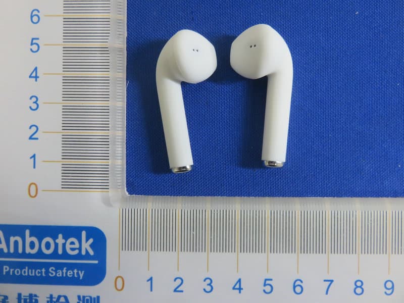
Click to zoom
Application Details
- Equipment Class
- DSS - Part 15 Spread Spectrum Transmitter
- Date of Grant
- May 19, 2020
- Application Purpose
- Original Equipment
- Date of Application
- May 19, 2020
- Equipment Note
- TWS Earbuds
- Frequency Range
- 2402.00000000 - 2480.00000000
- Company
- ARGENTOSC
- Country
- United States
Documents & Files
Document Text
Text extracted from the exhibit documents filed with the FCC. Open a document above to read the original.
Users Manual
55mm 70mm Front Back QUICK START GUIDE TRUE WIRELESS EARBUDS GETTING STARTED 7 2 3 1 6 5 4 R L 1 Micro USB charging port 2 Charging Case LED indicators 3 Charging Case Power Button 4 Left earbud LED indicator 5 Left control button 6 Right earbud LED indicator 7 Right control button L Left Earbud Right Earbud R Pause/Play/Answer Call/End Call, Next Track / — Charge on the go charging case, with the included micro USB cable for 2-3 hours. (LED (2A) will blink red) Do not charge longer than suggested time. Do not charge overnight. — When LED (2A) is illuminated solid red battery case is fully charged. Charging LED Indicators CHARGING YOUR CASE 2A2B 2A2B Flashing RED- Battery Case is charging Solid RED- Battery Case is fully charged Solid BLUE- Battery Case is charging earbuds OFF- Battery Case is off CHARGING YOUR EARBUDS — Place Right and Left Earbuds in battery case charging cradle and press the power button on the battery case (3) — Charging case LED indicator (2B) will illuminate Blue and the earbud LED indicators (4, 6) will illuminate Red, indicating that the earbuds are charging properly. When Earbuds LEDs (4, 6) turn solid blue, earbud batteries are fully charged. — After earbuds are fully charged, press the charging case power button (3) to turn the charging case OFF. MONO MODE (SINGLE EARBUD USE) — Remove earbud from charging cradle and power on by pressing the control button (7) or (5) for 3 seconds depending on which earbud your using. — Once earbud is powered on, proceed to PAIRING — Remove both earbuds from charging cradle and place them in your ears. — Make sure Bluetooth ® Search Mode is turned off on your mobile device. — Hold the right earbud button (7) for 3 seconds and then press left earbud button (5) for 3 seconds until they are powered on. (Earbud LEDs will flash Red and Blue to indicate that they are in Link mode.) — Earbuds will automatically link together after a few seconds,an d earbuds will have a tone (LEDs will flash blue) — Once Earbuds are linked together you may proceed to pairing with your mobile device. STEREO MODE (DUAL EARBUD USE) PAIRING *Note: 1Once earbuds have been initially paired successfully with 2. Ensure the earbuds are fully charged, then remove from the case. Press the button on each earbud for 3 seconds until you see th e flashing blue and red lights. Once both earbuds co nnected together, then pair with your phone. your mobile device they will automatically pair the next time — Enable Bluetooth search mode on your mobile device and search for pairing name “ TWS” and select it on your mobile phone. Once the earbuds are successfully paired a notification will sound . — Now you can enjoy your true wireless Bluetooth Earbuds. TWS-i7 OPERATING BLUETOOTH EARBUDS Function Operation Power On Press (5) or (7) for 3 seconds Power Off Press (5) or (7) for 5 seconds Play/Pause Single press (5) or (7) Answer Reject Earbuds LED indications (4) & (6) Power On Red and Blue LED will flash altemately Link Mode Flashing Blue + Red Paired Successfully Flashing Blue Power Off LED Off Earbuds in Cradle Charging Solid Red Fully Charged Solid Blue Charging CaseSeeCHARGING YOUR CASE Single press (5) or (7) Press (5) or (7) for 2 seconds they are powered on. Model: EB5566 FCCSTATEMENT: ThisdevicecomplieswithPart15oftheFCCRules.Operationissubject tothefollowingtwoconditions: (1)Thisdevicemaynotcauseharmfulinterference,and (2)Thisdevicemustacceptanyinterferencereceived,including interferencethatmaycauseundesiredoperation. Warning:Changesormodificationsnotexpresslyapprovedbytheparty responsibleforcompliancecouldvoidtheuser'sauthoritytooperatethe equipment. NOTE:Thisequipmenthasbeentestedandfoundtocomplywiththe limitsforaClassBdigitaldevice,pursuanttoPart15oftheFCCRules. Theselimitsaredesignedtoprovidereasonableprotectionagainst harmfulinterferenceinaresidentialinstallation.Thisequipment generatesusesandcanradiateradiofrequencyenergyand,ifnot installedandusedinaccordancewiththeinstructions,maycauseharmful interferencetoradiocommunications.However,thereisnoguarantee thatinterferencewillnotoccurinaparticularinstallation.Ifthisequipment doescauseharmfulinterferencetoradioortelevisionreception,which canbedeterminedbyturningtheequipmentoffandon,theuseris encouragedtotrytocorrecttheinterferencebyoneormoreofthe followingmeasures: Reorientorrelocatethereceivingantenna. Increasetheseparationbetweentheequipmentandreceiver. Connecttheequipmentintoanoutletonacircuitdifferentfromthatto whichthereceiverisconnected. Consultthedealeroranexperiencedradio/TVtechnicianforhelp. RFwarningstatement: ThedevicehasbeenevaluatedtomeetgeneralRFexposure requirement.Thedevicecanbeusedinportableexposurecondition withoutrestriction.
External Photos
FCC ID: 2AC5V-EB5566
ID Label/Location Info
Label Location On EUT LeftRight Label FCC ID: 2AC5V-EB5566
Internal Photos
FCC ID: 2AC5V-EB5566 ANT
Operational Description
version01 ARGENTOSC Declaration concerning Antenna Specification It is hereby declared that the product Model No.: EB5566, HP-104 FCC ID : 2AC5V-EB5566 fulfills the requirement in FCC test relating to the antenna type. The device specified above confirms to the FCC recommendations for internal antenna type(s) described below: Model No. of antenna: N/A Type of antenna:PCB Antenna Gain of the antenna: 0 dBi Frequency range: 2402MHz~2480MHz The mounting of the antenna is fixed to the radio module and no other antenna should be used. Company name: ARGENTOSC Address: 1407 Broadway Suite 2201 New York, NY 10018, USA City:New York ZIP / Postal code: N.A. Country:USA Place:New York Date: 2020-05-19 Signature:
RF Exposure Info
RF EXPOSURE EVALUATION FCC ID: 2AC5V-EB5566 According to FCC 1.1310: The criteria listed in the following table shall be used to evaluate the environment impact of human exposure to radio frequency(RF) Radiation as specified in §1.1307(b): Routine SAR evaluation refers to that specifically required by §2.1093, using measurements or computer simulation. When routine SAR evaluation is not required, portable transmitters withoutput power greater than the applicable low threshold require SAR evaluation to qualify for TCB approval. Channel (MHz) Maximum output power (dBm) Tune up tolerance (dBm) Max Tune Up Power (dBm) Distance (mm) Calculation results Limit Operating Mode 2402-1.599 -1.599±1 -0.59950.2703 BDR+EDR 24410.071 0.071±11.071 5 0.400 3 24801.425 1.425±1 2.42550.5503 2402-2.663 -2.663±1 -1.66350.2113 2441-1.200 -1.200±1 -0.20050.2983 2480-0.077 -0.077±1 0.92350.3903 Test Results:PASS.
Test Report
Report No.: 18220WC00021701FCC ID: 2AC5V-EB5566Page 1 of 63 Code:AB-RF-05-a FCC TEST REPORT Client Name: ARGENTOSC Address: 1407 Broadway Suite 2201 New York, NY 10018, USA Product Name: TWS Earbuds Date: May 19, 2020 Shenzhen Anbotek Compliance Laboratory Limited Report No.: 18220WC00021701FCC ID: 2AC5V-EB5566Page 2 of 63 Code:AB-RF-05-a Contents 1. General Information ............................................................................................................................................... 5 1.1. Client Information ....................................................................................................................................... 5 1.2. Description of Device (EUT) ..................................................................................................................... 5 1.3. Auxiliary Equipment Used During Test ................................................................................................... 6 1.4. Description of Test Modes ........................................................................................................................ 6 1.5. List of channels ........................................................................................................................................... 7 1.6. Description Of Test Setup ......................................................................................................................... 8 1.7. Test Equipment List .................................................................................................................................... 9 1.8. Measurement Uncertainty ....................................................................................................................... 10 1.9. Description of Test Facility ...................................................................................................................... 10 2. Summary of Test Results ................................................................................................................................... 11 3. Conducted Emission Test ................................................................................................................................... 12 3.1. Test Standard and Limit .......................................................................................................................... 12 3.2. Test Setup .................................................................................................................................................. 12 3.3. Test Procedure .......................................................................................................................................... 12 3.4. Test Data .................................................................................................................................................... 12 4. Radiation Spurious Emission and Band Edge ................................................................................................ 15 4.1. Test Standard and Limit .......................................................................................................................... 15 4.2. Test Setup .................................................................................................................................................. 15 4.3. Test Procedure .......................................................................................................................................... 16 4.4. Test Data .................................................................................................................................................... 17 5. Maximum Peak Output Power Test .................................................................................................................. 25 5.1. Test Standard and Limit .......................................................................................................................... 25 5.2. Test Setup .................................................................................................................................................. 25 5.3. Test Procedure .......................................................................................................................................... 25 5.4. Test Data .................................................................................................................................................... 25 6. 20DB Occupy Bandwidth Test ........................................................................................................................... 29 6.1. Test Standard ............................................................................................................................................ 29 6.2. Test Setup .................................................................................................................................................. 29 6.3. Test Procedure .......................................................................................................................................... 29 6.4. Test Data .................................................................................................................................................... 29 7. Carrier Frequency Separation Test ................................................................................................................... 33 7.1. Test Standard and Limit .......................................................................................................................... 33 7.2. Test Setup .................................................................................................................................................. 33 7.3. Test Procedure .......................................................................................................................................... 33 7.4. Test Data .........................................…
Text truncated - open the document above for the full version.
Test Setup Photos
FCC ID: 2AC5V-EB5566 Photo of Conducted Emission Measurement Photo of Radiation Emission Test
Contact Information
Applicant
Jack Scaba(General manager)
Test Firm
Shenzhen Anbotek Compliance Laboratory LimitedJeff Zhu
Technical Specifications
| # | Rule Parts | Frequency Range | Power Output |
|---|---|---|---|
| 1 | 15C | 2.40 GHz - 2.48 GHz | 1.40 mW |
Other Applications from ARGENTOSC
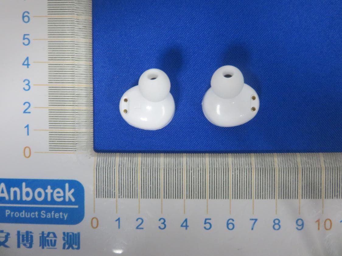
2AC5V-EB0197
Jan 14, 2020TWS Earbuds
Equipment Class
DSS - Part 15 Spread Spectrum Transmitter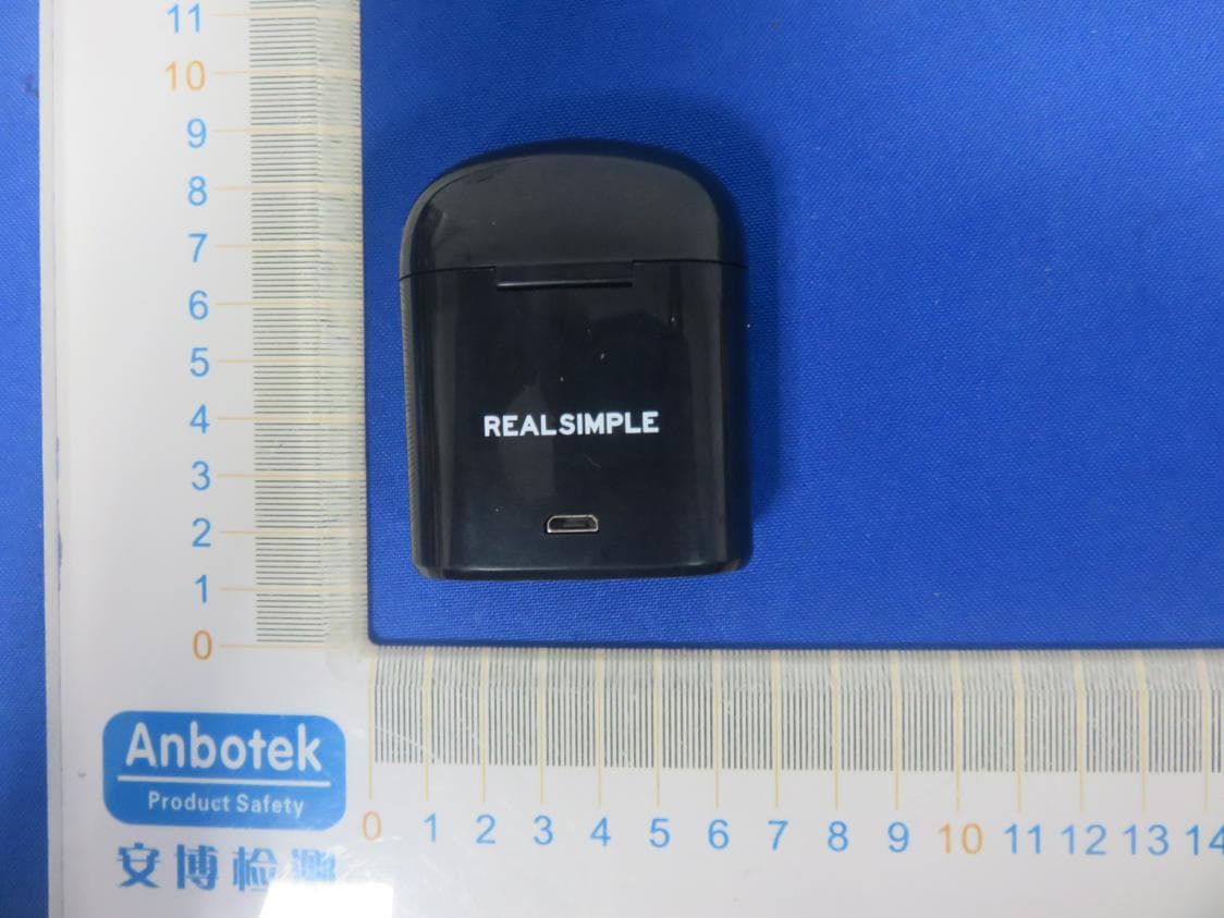
2AC5V-EB0203
Jan 14, 2020TWS Earbuds
Equipment Class
DSS - Part 15 Spread Spectrum Transmitter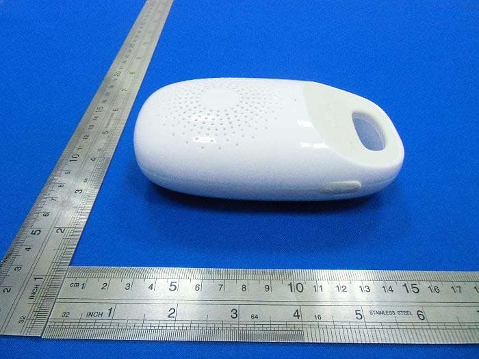
2AC5VGROUND009
Sep 19, 2014Shower Speaker
Equipment Class
DSS - Part 15 Spread Spectrum Transmitter