2ACA7-MCR5532CContactless Smart Card Reader
Honeywell (China) Co., LTD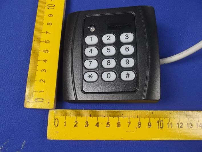
Click to zoom
Application Details
- Equipment Class
- DXX - Part 15 Low Power Communication Device Transmitter
- Date of Grant
- May 12, 2014
- Application Purpose
- Original Equipment
- Date of Application
- May 12, 2014
- Equipment Note
- Contactless Smart Card Reader
- Frequency Range
- 13.56000000 - 13.56000000
- Company
- Honeywell (China) Co., LTD
- Country
- China
Documents & Files
Document Text
Text extracted from the exhibit documents filed with the FCC. Open a document above to read the original.
Users Manual
Honeywell 1 / 2 Contactless Smart Card Reader Installation Instructions Model: JT-MCR45(55)-32C Rev 1.3, Apr.18th, 2014 WHAT IS THE Contactless Smart Card Reader? The Reader is an RFID Contactless Smart Card reader for use with access control systems. These installation instructions contain the following information: Mounting Instructions Connecting the reader to a host using the wiegand interface Testing and operation of the reader How to install the PSAM card? If the card reader is configured as software encrypted, it is no need the PSAM card. But if it is hardware encrypted, the PASM card is necessary. The steps to install the PSAM card are as follow: 1. Open the back cover of the reader first and then you could find the socket of PSAM card. 2. Push the deck lid on the socket in the direction of sign “OPEN”, and then open it. 3. Insert the flat side of PASM card (NOT THE SIDE WHICH HAS MISSING CORNER) alone the guide groove on the upper lid. Let the face which has contacts up (THIS SIDE WILL FACE DOWN AFTER CLOSE THE LID). After that, close the upper lid and push it in the opposite direction when open it, make sure the lid be locked and fastened reliably. 4. Close the back cover of the card reader. HOW TO MOUNT THE READER To surface mount the reader, perform the following: 1. Determine an appropriate mounting position for the reader. Ideally, for the maximum operating distance, avoid mounting the reader directly on metal surfaces. 2. Peel off the back of the self-stick mounting label template included with the unit and position it at the desired mounting position. 3. Using the template as a guide, drill two holes (hole size is indicated on mounting template) for mounting the reader to the surface. 4. Drill a 1/2′′ (13 mm) hole for the cable. If mounting on metal, place a grommet or electrical tape around the edge of the hole to protect the wire from chaffing. 5. Attach the reader to the mounting surface using the appropriate screws (not supplied). The mounting template may be left in place if desired since the reader will cover it completely. HOW TO CONNECT THE READER TO THE HOST The Reader is supplied with an 18-inchpigtail, having a 7-conductor cable. To connect the reader to the host, perform the following steps: 1. Prepare both the reader cable and host cables by cutting the cable jacket back 1¼ inches and strip the wires ½ inch. 2. Splice the reader pigtail wires to the corresponding host wires and cover each connection (see Figure 1). 3. Trim and cover all conductors that are not used. Figure 1 below shows how you should wire the reader to the host. Figure 1 Wiring Notes: 1. The individual wires coming out of the reader are color coded according to the recommended wiegand standard. 2. When using a separate power supply for the reader, the reader power supply and host must have a common ground. 3. The recommended cable depends on the distance from the reader to the host. See Table 1 below for the correct wire gage based upon distance. Larger wire gauges (smaller numbers) are desirable. The wire must be stranded with an overall Red +8~16VDC Black Ground White Data1 Green Data0 Brown LED Control Purple Tamper + Orange Tamper - Honeywell Model:JT-MCR45-32C Honeywell 2 / 2 ! shield, either foil or braided. 4. The cable shield wire on the reader should be attached to an Earth ground (best) or signal ground connection at the panel or power supply end of the cable. This configuration is best for shielding the reader cable from external interference. TABLE 1: WIRE GAGE SPECIFICATIONS Distance Gage 5 Conductor 6 Conductor = 200 ft. (61m) 22 Alpha 1295C Alpha 1296C =300 ft. (91m) 20 Alpha 58126 Alpha 58126 = 500 ft. (153 m) 18 Alpha 58136 Alpha 58136 Recommended cable is only a guideline, use any manufacturer that meets the gage and shield specifications. HOW TO TEST AND OPERATE THE READER The reader should be tested after wiring it to the host. Do this by performing the following steps: 1. Power up the reader. The LED and beeper will activate three times. This indicates that the reader is working properly. 2. Present the configuration card to the reader. Power up the reader. The LED and beeper will active two times in 1 ~ 10 seconds. This indicates that the reader is configuration successful.(Must configured in 3 seconds after power up) 3. Present a Contactless Smart Card to the reader. The LED will momentarily flash green and beep will activate one time (if the reader is the factory default configuration). This indicates that the card was read properly by reader. 4. After the card data is processed by the host, the host turn the LED green. Refer to the host description of the LED operation if the reader LED is controlled by the host. SPECIFICATIONS Electrical Characteristics: Frequency: 13.56 MHz Power Supply Type: Linear or switching; ripple < 50 mVpp Operating Voltage Range: 8.0 – 16 VDC Maximum input current: 120 mA Maximum Cable Distance to Host: 500 ft. (150 meters) Output Interface: Wiegand 32 ( User-defined Support) Tamper Output: NC Card Supported: ISO14443 CPU Card Card Read Distance(Normal Use): More than 3cm Operating Temperature Range: -25° F to 145° F (-31°C to 63°C) Operating Humidity: 0 to 95% (non-condensing) Dimensions: 3.5′′(89mm) L x 3.5′′(89mm) W x 0.8′′(20mm) D FCC STATEMENT : This device complies with Part 15 of the FCC Rules. Operation is subject to the following two conditions: 1) This device may not cause harmful interference, and 2) This device must accept any interference received, including interference that may cause undesired operation. Warning: Changes or modifications not expressly approved by the party responsible for compliance could void the user's authority to operate the equipment. NOTE: This equipment has been tested and found to comply with the limits for a Class B digital device, pursuant to Part 15 of the FCC Rules. These limits are designed to provide reasonable protection against harmful interference in a residential installation. This equ…
Text truncated - open the document above for the full version.
Cover Letter(s)
SCS-F19: Confidentiality Request Letter Page 1 of 2 Rev 3.0 775 Montague Expressway Milpitas, CA 95035 Tel: 408-526-1188 Fax: 408-526-1088 Email: [email protected] Confidentiality Request Letter Reason for Amendment (current / obsolete) Revision History Approved Date From To Initial Release (obsolete) 1.0 1.0 Nov-14-2006 Adding CFR 2.459 (obsolete) 1.0 2.0 August – 11 - 2008 Updated company template & Added text box (current) 2.0 3.0 Jan-31-2012 SCS-F19: Confidentiality Request Letter Page 2 of 2 Rev 3.0 (Honeywell (China) Co., LTD) (2014-4-24) To: Federal Communications Commission Authorization and Evaluation Division 7435 Oakland Mills Road Columbia, MD Subject: Permanent Confidentiality Request for FCC ID: 2ACA7-MCR5532C We hereby request confidential treatment of information accompanying this application as outlined below: - Block Diagram - Schematics - Operational Description The above materials contain trade secrets and proprietary information not customarily released to the public. The public disclosure of these materials may be harmful to the applicant and provide unjustified benefits to its competitors. The applicant understands that pursuant to Section 0.457 & 0.459 of the Rules, disclosure of this application and all accompanying documentation will not be made before the date of the Grant for this application. Sincerely, Chuanwen Yang/ Design Assurance Engineer Company Name: Honeywell (China) Co., LTD Address: Block 28, Section 2, Huai De Cui Gang Industrial Estate, Fu Yong, Bao An, Shenzhen, 518103, China
External Photos
Figure 1 The EUT-Overall View Figure 2 The EUT-Front View Figure 3 The EUT- Back View Figure 4 The EUT-Top View Figure 5 The EUT-Bottom View Figure 6 The EUT-Left View Figure 7 The EUT-Right View
ID Label/Location Info
Product Name: Contactless Smart Card Reader Model No.: JT-MCR55-32C FCC ID: 2ACA7-MCR5532C This device complies with Part 15 of the FCC Rules. Operation is subject to the following two conditions: (1) This device may not cause harmful interference, and (2) This device must accept any interference received, including interference that may cause undesired operation.
ID Label/Location Info
Label Location On EUT
Internal Photos
Figure 4 The EUT-Inside View Figure 5 PCB of the EUT View Figure 6 PCB of the EUT View Figure 7 PCB of the EUT View Figure 8 PCB of the EUT View
Test Report
Shenzhen Anbotek Compliance Laboratory Limited FCC ID: 2ACA7-MCR5532C Page 1 of 30 Report No.: 201312889F Shenzhen Anbotek Compliance Laboratory Limited Tel: (86)755-26066544 Fax: (86)755-26014772 www.anbotek.com FCC TEST REPORT for Honeywell (China) Co., LTD Contactless Smart Card Reader Model No.: JT-MCR55-32C Prepared for : Honeywell (China) Co., LTD Address : Block 28, Section 2, Huai De Cui Gang Industrial Estate, Fu Yong, Bao An, Shenzhen, 518103, China Prepared By : Shenzhen Anbotek Compliance Laboratory Limited Address : 1/F., Building 1, SEC Industrial Park, No.0409 Qianhai Road, Nanshan District, Shenzhen, Guangdong, China Tel: (86) 755-26066544 Fax: (86) 755-26014772 Report Number : 201312889F Date of Test : Jan. 08~ Apr. 20, 2014 Date of Report : Apr. 20, 2014 Shenzhen Anbotek Compliance Laboratory Limited FCC ID: 2ACA7-MCR5532C Page 2 of 30 Report No.: 201312889F Shenzhen Anbotek Compliance Laboratory Limited Tel: (86)755-26066544 Fax: (86)755-26014772 www.anbotek.com TABLE OF CHONTENTS Description Page 1. GENERAL INFORMATION ............................................................................................................ 4 1.1. Description of Device (EUT) ..........................................................................................................................4 1.2. Auxiliary Equipment Used during Test ..........................................................................................................5 1.3. Description of Test Facility .............................................................................................................................5 1.4. Measurement Uncertainty ...............................................................................................................................5 2. TEST PROCEDURE ............................................................................................................................. 6 3. POWER LINE CONDUCTED MEASUREMENT ............................................................................ 7 3.1. Block Diagram of Test Setup ..........................................................................................................................7 3.2. Power Line Conducted Emission Measurement Limits (FCC Part 15 15.207) ...............................................7 3.3. Configuration of EUT on Measurement ..........................................................................................................7 3.4. Operating Condition of EUT ...........................................................................................................................7 3.5. Test Procedure .................................................................................................................................................8 3.6. Power Line Conducted Emission Measurement Results .................................................................................8 4. RADIATED EMISSION MEASUREMENT ..................................................................................... 11 4.1. Radiated Emission Limits .............................................................................................................................11 4.2. Test Procedure ...............................................................................................................................................11 4.3. Test Setup ......................................................................................................................................................12 4.4. Test Results (Field Strength within the band of operation) ...........................................................................14 4.5. Test Results (Field strength outside of the band of operation) ......................................................................14 5. FREQUENCY TOLERANCE ............................................................................................................ 17 5.1. Frequency Tolerance Limits ..........................................................................................................................17 5.2. Test Setups ....................................................................................................................................................17 5.3. Test Procedure ...............................................................................................................................................17 5.4. Test Results ...................................................................................................................................................18 6. 20DB BANDWIDTH ............................................................................................................................ 19 6.1. Limits ............................................................................................................................................................19 6.2. Test Setups ....................................................................................................................................................19 6.3. Test Procedure ...............................................................................................................................................19 6.4. Test Results ...................................................................................................................................................19 7. ANTENNA APPLICATION ............................................................................................................... 21 7.1. Antenna Requirement ....................................................................................................................................21 7.2. Result .............................................................................................................................................................21 8. PHOTOGRAPH ............................................................…
Text truncated - open the document above for the full version.
Test Setup Photos
1. Photo of Conducted Emission Test 2. Photo of Radiated Emission Test
Contact Information
Applicant
Chuanwen Yang(Design Assurance Engineer)
Test Firm
Shenzhen Anbotek Compliance Laboratory LimitedDaniel zhu
[email protected]86-755-26014771
Technical Specifications
| # | Rule Parts | Frequency Range | Power Output |
|---|---|---|---|
| 1 | 15C | 13.56 MHz - 13.56 MHz | - |