2ACB3-KYPROBluetooth headset
ShenZhen FreedConn(FDC) Electronics Co., Ltd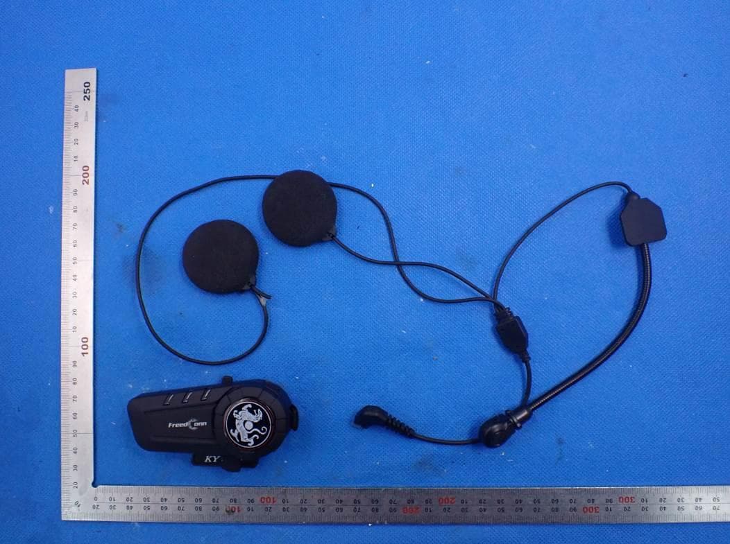
Click to zoom
Application Details
- Equipment Class
- DSS - Part 15 Spread Spectrum Transmitter
- Date of Grant
- Jan 21, 2021
- Application Purpose
- Original Equipment
- Date of Application
- Jan 21, 2021
- Equipment Note
- Bluetooth headset
- Frequency Range
- 2402.00000000 - 2480.00000000
- Country
- China
Documents & Files
Document Text
Text extracted from the exhibit documents filed with the FCC. Open a document above to read the original.
Users Manual
Shenzhen Freedconn(FDC) Electronics Co., Ltd Bluetooth headset KY PRO Freedconn 一、 Introduction Thank you for choosing FreedConn KY PRO Motorcycle Bluetooth Communication System. T-Rex is a Full Duplex Group Talk Bluetooth System, applying humanized design, integrating the cutting edge technology of all similar products and becoming a perfect motorcycle communication system. It can satisfy all kinds of needs in your journey, such as wireless dialling, receiving calls, listening to Mp3 music, receiving GPS voice prompt and connecting with handheld interphone. The most important is that it can realize group talk among motorcycles, providing you convenient communication with your teammates throughout the ride. 二、 Main Functions 1.6 -way 1000m conference talkback 2. Multiple device connected simultaneously 3. Wired/wireless connection with handheld interphone 4. Built-in radio 5. Voice prompt 6. Usable during recharging 三、 Functions and Operation of Buttons 1.On/Off button and talkback button 2.Multi-functional button 3.Recharging port 4.headphone jack 5.LED indicator light . 四、 Pack Content 1. Bluetooth device2.Universal clamp 3. USB cable4.Microphone& speaker 5. Headphone VELCRO6.Handheld interphone control cable 7. PTT VELCRO tape8.Manual 五、Installation Procedure 1. Loosen the screws on the back of clamp with the provided screw driver. 2. Open the lining of helmet,insret the clamp in the proper pasition on the left of helmet and fasten the screw (overly fastened screw can damage the clamp) 3.Slide the receiver do wn into the slots on the headset clamp mount.Make sure that it is locked in securely. 4. open the lining of helmet (at ear's position), clean the EPS surface adn affix the Velcro on with the rough surface. 5. Affix the hook surface of speaker to the rough surface of VELCRO and properly tidy the helmet lining. 6. Insert the headphone plug into the corresponding headphone jack on the receiver to finish the installation. 六、 Functions and Operation of Buttons 1. On/Off button and talkback button 1.1 On:press down for 3 seconds until hear "Welcome to use FreedConn product" voice prompt. The blue light will flash 3 times swiftly and then turn into regular flashing.。 1.2 Off: press down for 5 seconds until hear "Power off" voice prompt. The red。 1.3 Start Bluetooth talkback: shortly press the On/Off button on either one of the two paired T-Rex and a voice prompt will be heard after completing the talkback connection. 1.4 Close Bluetooth talkback: shortly press the button and talkback closes after a "bee" prompt tone. 1.5 Talkback/music switch: shortly press the button and a "bee" prompt tone can be heard. 1.5 Clear pairing address: when press down the On/Off button to start the device, hold the button down for another 3 seconds after the red light flashes until the red light quickly flashes 3 times and a "toot" prompt tone can be heard, which means clearing successful and the device is started. (Pressing down for 5 seconds when shutting down the device does not clear address) Note: the clearing will clear all memories; Press down for 8 seconds to enter pairing status if pairing address is not cleared and press down for 5 seconds to automatically enter pairing status if pairing address is cleared. Multi-functional Button 2.1 Receive calls: shortly press the button, a "Call answer" voice prompt can be heard. Incoming call will be received automatically answered when no operation is conducted after 15 seconds of ringing of incoming calls. 2.2 Reject calls: press down for 2 seconds until you hear "Call reject". 2.3 Switch between phone and voice: press down for 2 seconds until you hear "bee". 2.4 End the call: press the button or use mobile phone to end the call as usual. 2.5 Voice dialling: press down for 2 seconds until you hear "Voice dial". 2.6 Play/Pause music: press the button when playing music on mobile phone. 2.7 Play/Pause radio: double press the button when there is no call or talkback. 2.9 Switch between phones: phone A and B both being connected, if phone B receives a call when phone is in talk, press the multi-functional button to end phone A's talk and press another time to answer phone B's incoming call. 2.10 Switch between phone and interphone: when you receive a call during talkback, press down the button for 2 seconds to end talkback, press once more to answer the incoming call and talkback will be resumed after the call. 2.1 1 Switch between interphone and phone: when you receive a talkback invitation during a call, press the button to end the call and talkback will be switched in automatically. 2.12 FM: turn the knob clockwise to switch to next channel. Turn the knob counter clockwise to return to the previous channel. 2.13 Music play control: turn the knob clockwise to switch to next song. Turn the knob counter clockwise to return to the previous song. 2.14 Volume control: turn the knob clockwise and hold it to increase volume until it reaches the level you want. A "toot" prompt will be heard when it reaches Max volume; Turn the knob counter clockwise and hold it to decrease volume until it reaches the level you want. A "toot" prompt will also be heard when it reaches Min volume. 七. Pairing Method 1.Pair with Mobile Phone, Mp3 and GPS Step 1: Ensure KY PRO is off and within 1 m visible range of the device to be paired. Step 2: Press down the T-Rex On/Off/Talkback button for 8 seconds until you hear "Pairing" prompt, when the red light and blue light flash alternatively, T-Rex enters pairing status. Step 3: Start the Bluetooth device to be paired, search and choose T-Rex to pair. When you hear "Your phone is connected" prompt and the blue light flashes regularly, pairing is successful. 2. Pairing between KY PRO Step 1: Ensure both KY PRO are off and within 1 m range of each other. Step 2: Press down both KY PRO On/Off/Talkback buttons for 8 seconds until you hear "Pairing" prompt from both KY PRO, when the red light and blue light flash alternatively, both KY PRO enter …
Text truncated - open the document above for the full version.
Cover Letter(s)
ShenZhen FreedConn(FDC) Electronics Co., Ltd East Area 4th floor, E building, Hua Chuang Da industry park, No.176 HangCheng Road, Xixiang, Baoan, Shenzhen, China Agent Authorization Company: ShenZhen FreedConn(FDC) Electronics Co., Ltd Address: East Area 4th floor, E building, Hua Chuang Da industry park, No.176 HangCheng Road, Xixiang, Baoan, Shenzhen, China Product Name: Bluetooth headset Model Number(s): KY PRO, KY Product Description: Bluetooth headset We authorize MiCOM Labs Inc., 575 Boulder Court, Pleasanton, California 94566, USA, to act on our behalf on all matters concerning the certification of above named equipment. We declare that MiCOM Labs Inc. is allowed to forward all information related to the approval and certification of equipment to the regulatory agencies as required and to discuss any issues concerning the approval application. Any and all acts carried out by MiCOM Labs on our behalf shall have the same effect as acts of our own. Signature: Date: Jan. 07, 2021 Name: Wang Honghai Title: General Manager Company: ShenZhen FreedConn(FDC) Electronics Co., Ltd
Cover Letter(s)
ShenZhen FreedConn(FDC) Electronics Co., Ltd East Area 4th floor, E building, Hua Chuang Da industry park, No.176 HangCheng Road, Xixiang, Baoan, Shenzhen, China Jan. 07, 2021 Office of Engineering Technology Federal Communications Commission 7435 Oakland Mills Road Columbia, MD 21046 USA Subject: Explanation of differences between product types FCC ID: 2ACB3-KYPRO Models: KY PRO, KY To Whom It May Concern: We, The ShenZhen FreedConn(FDC) Electronics Co., Ltd hereby declare that the model : KY is identical with the model : KY PRO, except the model name. Except for the different above, no other modification is performed. Sincerely, ShenZhen FreedConn(FDC) Electronics Co., Ltd Signature: [Wang Honghai, General Manager]
External Photos
External Photos WHOLE VIEW OF EUT TOP VIEW OF EUT BOTTOM VIEW OF EUT FRONT VIEW OF EUT BACK VIEW OF EUT LEFT VIEW OF EUT RIGHT VIEW OF EUT VIEW OF EUT(PORT)-1 VIEW OF EUT(PORT)-2
ID Label/Location Info
FCC ID Label Location 20mm*20mm FCC ID: 2ACB3-KYPRO
Internal Photos
Internal Photos OPEN VIEW OF EUT-1 OPEN VIEW OF EUT-2 VIEW OF BATTERY INTERNAL VIEW OF EUT-1 INTERNAL VIEW OF EUT-2 INTERNAL VIEW OF EUT-3 BT Antenna
RF Exposure Info
RF EXPOSURE EVALUATION 1. PRODUCT INFORM ATION Product Description Bluetooth headset Model Name KY PRO, KY FCC ID 2ACB3-KYPRO 2. EVALUATION M ETHOD According to 447498 D01 General RF Exposure Guidance v06 The 1-g and 10-g SAR test exclusion thresholds for 100 MHz to 6 GHz at test separation distances ≤ 50 mm are determined by: [(max. power of channel, including tune-up tolerance, mW)/(min. test separation distance, mm)] ·[√f(GHz)] ≤ 3.0 for 1-g SAR and ≤ 7.5 for 10-g extremity SAR. Where f(GHz) is the RF channel transmit frequency in GHz Power and distance are rounded to the nearest mW and mm before calculation 3. CALCULATION BR/EDR: P t =2.608dBm=1.82mW The value of the Maximum output power P t is referred to the test report of the CFR47 §15.247. The result for RF exposure evaluation SAR=(1.82mW /5mm) .[√2.402GHz)]=0.56<3.0 for 1-g SAR and ≤ 7.5 for 10-g extremity SAR. 4. CONCLUSION The SAR evaluation is not required.
Test Report
Page 1 of 72 FCC Test Report Report No.: AGC00805201201FE03 FCC ID : 2ACB3-KYPRO APPLICATION PURPOSE : Original Equipment PRODUCT DESIGNATION : Bluetooth headset BRAND NAME : Freedconn MODEL NAME : KY PRO, KY APPLICANT : ShenZhen FreedConn(FDC) Electronics Co., Ltd DATE OF ISSUE : Jan. 22, 2021 STANDARD(S) : FCC Part 15.247 REPORT VERSION : V1.0 Attestation of Global Compliance (Shenzhen) Co., Ltd Report No.: AGC00805201201FE03 Page 2 of 72 REPORT REVISE RECORD Re port Ve rsion Re v ise Time Issue d Date Valid Ve rsion Note s V1.0 / Jan. 22, 2021 Valid Initial Release Report No.: AGC00805201201FE03 Page 3 of 72 TABLE OF CONTENTS 1. VERIFICATION OF CONFORM ITY ............................................................................................................. 5 2. GENERAL INFORM ATION ......................................................................................................................... 6 2.1. PRODUCT DESCRIPTION ................................................................................................................... 6 2.2. TABLE OF CARRIER FREQUENCYS ................................................................................................... 6 2.3. RECEIVER INPUT BANDWIDT H .......................................................................................................... 7 2.4. EXAMPLE OF A HOPPING SEQUENCY IN DATA MODE...................................................................... 7 2.5. EQUALLY AVERAGE USE OF FREQUENCIES AND BEHAVIOUR ....................................................... 7 2.6. RELATED SUBMITTAL(S) / GRANT (S) ................................................................................................ 8 2.7. TEST METHODOLOGY........................................................................................................................ 8 2.8. SPECIAL ACCESSORIES .................................................................................................................... 8 2.9. EQUIPMENT MODIF ICAT IONS ............................................................................................................ 8 2.10. ANTENNA REQUIREMENT................................................................................................................ 8 3. M EASUREM ENT UNCERTAINTY .............................................................................................................. 9 4. DESCRIPTION OF TEST M ODES ............................................................................................................ 10 5. SYSTEM TEST CONFIGURATION ............................................................................................................11 5.1. CONFIGURATION OF EUT SYSTEM ..................................................................................................11 5.2. EQUIPMENT USED IN TESTED SYSTEM...........................................................................................11 5.3. SUMMARY OF TEST RESULTS ..........................................................................................................11 6. TEST FACILITY ........................................................................................................................................ 12 7. PEAK OUTPUT POWER .......................................................................................................................... 13 7.1. MEASUREMENT PROCEDURE......................................................................................................... 13 7.2. TEST SET-UP (BLOCK DIAGRAM OF CONFIGURATION) ................................................................. 13 7.3. LIMITS AND MEASUREMENT RESULT ............................................................................................. 14 8. 20DB BANDWIDTH .................................................................................................................................. 20 8.1. MEASUREMENT PROCEDURE......................................................................................................... 20 8.2. TEST SET-UP (BLOCK DIAGRAM OF CONFIGURATION) ................................................................. 20 8.3. LIMITS AND MEASUREMENT RESULTS ........................................................................................... 21 9. CONDUCTED SPURIOUS EM ISSION ...................................................................................................... 27 9.1. MEASUREMENT PROCEDURE......................................................................................................... 27 Report No.: AGC00805201201FE03 Page 4 of 72 9.2. TEST SET-UP (BLOCK DIAGRAM OF CONFIGURATION) ................................................................. 27 9.3. MEASUREMENT EQUIPMENT USED ................................................................................................ 27 9.4. LIMITS AND MEASUREMENT RESULT ............................................................................................. 27 10. RADIATED EM ISSION ............................................................................................................................ 40 10.1. MEASUREMENT PROCEDURE....................................................................................................... 40 10.2. TEST SETUP .................................................................................................................................... 42 10.3. LIMITS AND MEASUREMENT RESULT ........................................................................................... 43 10.4. TEST RESULT .................................................................................................................................. 43 11. NUM BER OF HOPPING FREQUENCY................................................................................................... 53 11.1. MEASUREMENT PROCEDURE ..............................................................................…
Text truncated - open the document above for the full version.
Test Report
Report No.: AGC00805201201FE03 Page 51 of 72 EUT Bluetooth headset M ode l Name KY PRO Te mpe rature 25°C Re lativ e Humidity 55.4% Pre ssure 960hPa Te st Voltage Normal Voltage Te st M ode Mode 3 Ante nna Horizontal PK AV RESULT: PASS Report No.: AGC00805201201FE03 Page 52 of 72 EUT Bluetooth headset M ode l Name KY PRO Te mpe rature 25°C Re lativ e Humidity 55.4% Pre ssure 960hPa Te st Voltage Normal Voltage Te st M ode Mode 3 Ante nna Vertical PK AV RESULT: PASS Note: The factor had been edited in the “Input Correction” of the Spectrum Analyzer. The GFSK modulation is the worst case and recorded in the report. Report No.: AGC00805201201FE03 Page 53 of 72 11. NUMBER OF HOPPING FREQUENCY 11.1. M EASUREM ENT PROCEDURE The EUT shall have its hopping function enabled. Use the following spectrum analyzer settings: 1. Span: The frequency band of operation. Depending on the number of channels the device supports, it may be necessary to divide the frequency range of operation across multiple spans, to allow the individual channels to be clearly seen. 2. RBW: To identify clearly the individual channels, set the RBW to less than 30% of the channel spacing or the 20 dB bandwidth, whichever is smaller. 3. VBW ≥ RBW. Sweep: Auto. Detector function: Peak. Trace: Max hold. 4. Allow the trace to stabilize. 11.2. TEST SETUP (BLOCK DIAGRAM OF CONFIGURATION) Same as described in section 8.2 11.3. M EASUREM ENT EQUIPM ENT USED The same as described in section 6 11.4. LIM ITS AND M EASUREM ENT RESULT TOTAL NO. OF HOPPING CHANNEL LIM IT (NO. OF CH) M EASUREM ENT (NO. OF CH) RESULT >=15 79 PASS TEST PLOT FOR NO. OF TOTAL CHANNELS Note: The GFSK modulation is the worst case and recorded in the report. Report No.: AGC00805201201FE03 Page 54 of 72 12. TIME OF OCCUPANCY (DWELL TIME) 12.1. M EASUREM ENT PROCEDURE The EUT shall have its hopping function enabled. Use the following spectrum analyzer settings: 1. Span: Zero span, centered on a hopping channel. 2. RBW shall be≤channel spacing and where possible RBW should be set >> 1 / T, where T is the expected dwell time per channel. 3. Sweep: As necessary to capture the entire dwell time per hopping channel; where possible use a video trigger and trigger delay so that the transmitted signal starts a little to the right of the start of the plot. The trigger level might need slight adjustment to prevent triggering when the system hops on an adjacent channel; a second plot might be needed with a longer sweep time to show two successive hops on a channel. 4. Detector function: Peak. Trace: Max hold. 5. Use the marker-delta function to determine the transmit time per hop. 6. Repeat the measurement using a longer sweep time to determine the number of hops over the period specified in the requirements. The sweep time shall be equal to, or less than, the period specified in the requirements. Determine the number of hops over the sweep time and calculate the total number of hops in the period specified in the requirements, using the following equation: (Number of hops in the period specified in the requirements) = (number of hops on spectrum analyzer) × (period specified in the requirements / analyzer sweep time) 7. The average time of occupancy is calculated from the transmit time per hop multiplied by the number of hops in the period specified in the requirements. 12.2. TEST SETUP (BLOCK DIAGRAM OF CONFIGURATION) Same as described in section 8.2 12.3. M EASUREM ENT EQUIPM ENT USED The same as described in section 6 12.4. LIM ITS AND M EASUREM ENT RESULT Channe l Time of Pulse for DH5 (ms) Numbe r of hops in the pe riod spe cified in the re quire me nts Swe e p Time (ms) Limit (ms) Low 2.902 27*4 313.416 400 Middle 2.902 26*4 301.808 400 High 2.903 27*4 313.524 400 Note: The GFSK modulation is the worst case and recorded in the report. Report No.: AGC00805201201FE03 Page 55 of 72 TEST PLOT OF LOW CHANNEL Report No.: AGC00805201201FE03 Page 56 of 72 TEST PLOT OF MIDDLE CHANNEL Report No.: AGC00805201201FE03 Page 57 of 72 TEST PLOT OF HIGH CHANNEL Report No.: AGC00805201201FE03 Page 58 of 72 13. FREQUENCY SEPARATION 13.1. M EASUREM ENT PROCEDURE The EUT shall have its hopping function enabled. Use the following spectrum analyzer settings: 1. Span: Wide enough to capture the peaks of two adjacent channels. 2. RBW: Start with the RBW set to approximately 30% of the channel spacing; adjust as necessary to best identify the center of each individual channel. 3. Video (or average) bandwidth (VBW) ≥ RBW. 4. Sweep: Auto. e) Detector function: Peak. f) Trace: Max hold. g) Allow the trace to stabilize. Use the marker-delta function to determine the separation between the peaks of the adjacent channels. 13.2. TEST SETUP (BLOCK DIAGRAM OF CONFIGURATION) Same as described in section 6.2 13.3. M EASUREM ENT EQUIPM ENT USED The same as described in section 6.3 13.4. LIM ITS AND M EASUREM ENT RESULT CHANNEL CHANNEL SEPARATION LIM IT RESULT MHz Pass Hopping mode 1.000 20 dB BW TEST PLOT FOR FREQUENCY SEPARATION Note: The GFSK modulation is the worst case and recorded in the report. Report No.: AGC00805201201FE03 Page 59 of 72 14. FCC LINE CONDUCTED EMISSION TEST 14.1. LIM ITS OF LINE CONDUCTED EM ISSION TEST Fre que ncy M aximum RF Line Voltage Q.P. (dBμV) Av e rage (dBμV) 150kHz~500kHz 66-56 56-46 500kHz~5MHz 56 46 5MHz~30MHz 60 50 Note: 1. The lower limit shall apply at the transition frequency. 2. The limit decreases linearly with the logarithm of the frequency in the range 0.15 MHz to 0.50 MHz. 14.2. BLOCK DIAGRAM OF LINE CONDUCTED EM ISSION TEST EUT & Support Units Report No.: AGC00805201201FE03 Page 60 of 72 14.3. PRELIM INARY PROCEDURE OF LINE CONDUCTED EM ISSION TEST 1. The equipment was set up as per the test configuration to simulate typical actual usage per the user’s manual. When the EUT is a tabletop system, a wooden table with a height of 0.8 meters is used and is placed on the ground plane as per ANSI C63.10 (see Test Facility for the dimensions of the ground plane used). Whe…
Text truncated - open the document above for the full version.
Test Setup Photos
Test Setup Photos RADIATED EMISSION TEST SETUP BELOW 1GHz RADIATED EMISSION TEST SETUP ABOVE 1GHz CONDUCTED EMISSION TEST SETUP CONDUCTED TEST SETUP
Contact Information
Applicant
Wang Honghai
Technical Contact
Test Firm
Attestation of Global Compliance (Shenzhen) Co., LDoris Li
[email protected]+86-755-25234088
Technical Specifications
| # | Rule Parts | Frequency Range | Power Output |
|---|---|---|---|
| 1 | 15C | 2.40 GHz - 2.48 GHz | 1.80 mW |
Other Applications from ShenZhen FreedConn(FDC) Electronics Co., Ltd

2ACB3-BLADE
Aug 18, 2026Helmet Bluetooth Intercom Headset
Equipment Class
DSS - Part 15 Spread Spectrum Transmitter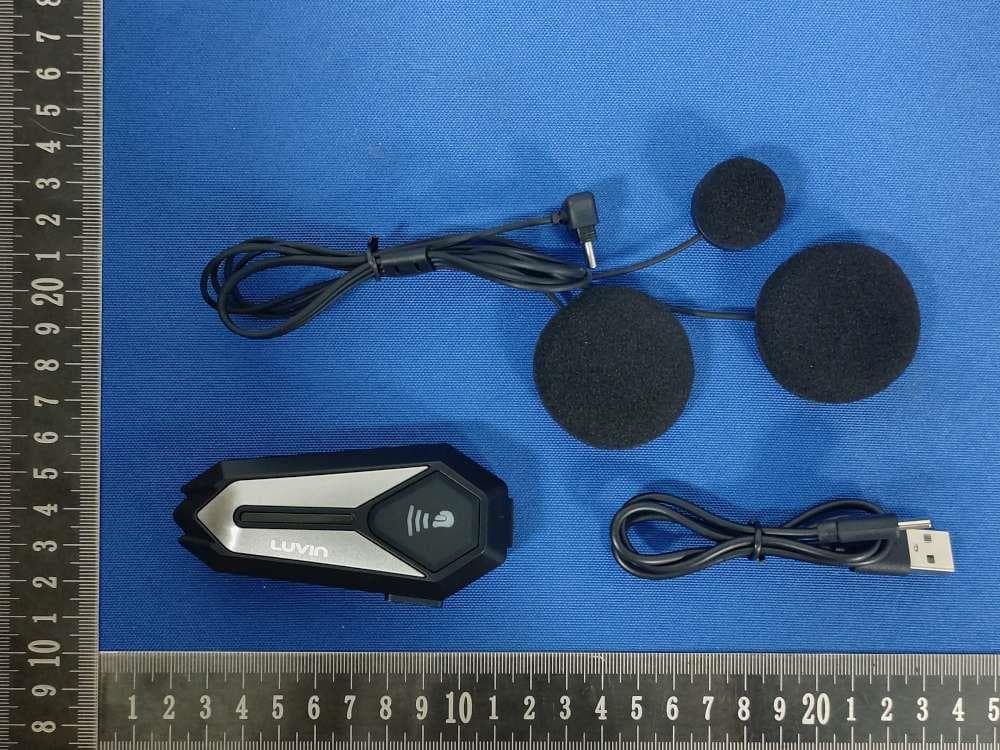
2ACB3-G8
Oct 10, 2024Helmet Bluetooth Intercom Headset
Equipment Class
DSS - Part 15 Spread Spectrum Transmitter
2ACB3-R3
Mar 26, 2023Motorcycle Bluetooth Headset
Equipment Class
DSS - Part 15 Spread Spectrum Transmitter
2ACB3-R1
Jan 13, 2020Bluetooth wifi recorder
Equipment Class
DSS - Part 15 Spread Spectrum Transmitter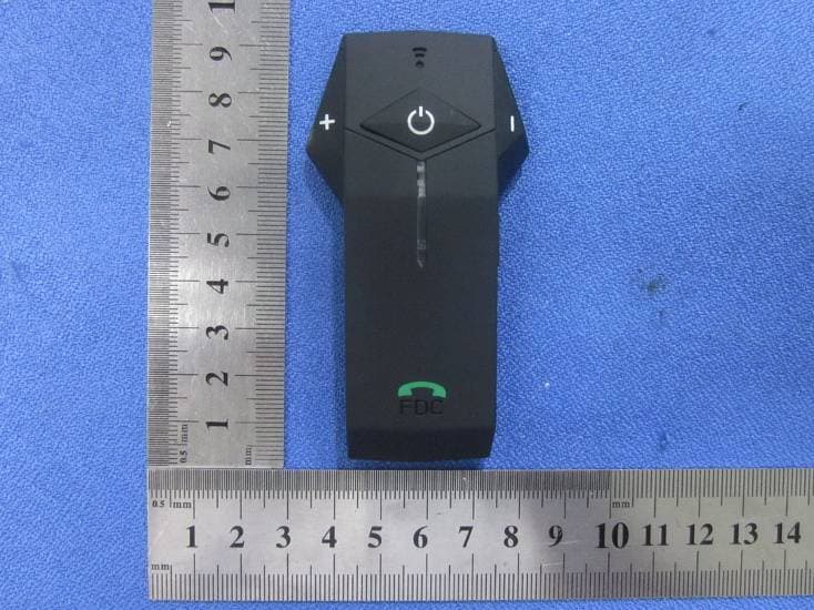
2ACB3-COLO
May 06, 2014Motorcycle Bluetooth Intercom Headset
Equipment Class
DXX - Part 15 Low Power Communication Device Transmitter