Text extracted from the exhibit documents filed with the FCC. Open a document above to read the original.
1 802.11n/b/g Wireless Outdoor High Power Access Point System version 1.0 User Manual Apply to: ALCON ACP24 ALCON AMU24 2 U FCC Notices This device complies with Part 15 of the FCC Rules. Operation is subject to the following two conditions: (1) this device may not cause harmful interference, and (2) this device must accept any interference received, including interference that may cause undesired operation. CAUTION: Change or modification not expressly approved by the party responsible for compliance could void the user’s authority to operate this equipment. This equipment has been tested and found to comply with the limits for a Class B digital device, pursuant to Part 15 of the FCC Rules. These limits are designed to provide reasonable protection against harmful interference in a residential installation. This equipment generates, uses and can radiate radio frequency energy and, if not installed and used in accordance with the instructions, may cause harmful interference to radio communications. However, there is no guarantee that interference will not occur in a particular installation. If this equipment does cause harmful interference to radio or television reception, which can be determined by turning the equipment off and on, the user is encouraged to try to correct the interference by one or more of the following measures: --Reorient or relocate the receiving antenna. --Increase the separation between the equipment and receiver. --Connect the equipment into an outlet on a circuit different from that to which the receiver is connected. --Consult the dealer or an experienced radio/TV technician for help. CAUTION: Any changes or modifications not expressly approved by the grantee of this device could void the user's authority to operate the equipment. RF exposure warning: The equipment complies with FCC RF exposure limits set forth for an uncontrolled environment. The equipment must not be co-located or operating in conjunction with any other antenna or transmitter. 3 Revision History Version Date Notes 0.2.4 August , 2013 Initial Version 0.2.8 January , 2014 Add some features 0.3.2 April , 2014 Released version 4 AP Configuration Using Locator While entering the Locator utility, the Locator will automatically search the AP available on the same network. Locator will show the Device Name, Device Type, IP Address, Ethernet MAC Address and Firmware Version in first page. Before start using Locator, make sure you disable personal firewall installed in you PC. (Ex. Windows XP personal firewall) If you have 2 Fast Ethernet Adapter or more, you can choose enable one Fast Ethernet Adapter for enter with Locator utility. AP Configuration Using Web User Interface Before Setup... Verify the IP address setting You need to configure your PC’s network settings to obtain an IP address. Computers use IP addresses to communicate with each other across a network, such as the Internet. 1. Click Start, select Control Panel. Double-click the Network Connections. 2. Right click the Local Area Connection and click Properties; select Internet Protocol (TCP/IP) for the applicable Ethernet adapter. Then click Properties. 3. Select USE the following IP address, enter 192.168.254.254 (but, 192.168.x.x for the device use) in the IP Address field and 255.255.0.0 in the Subnet Mask field, then click OK. Start Setup by Browser... 1. After getting the correct connection, start the web browser (make sure you disable the proxy) and enter 192.168.x.x (x is outdoor unit IP Address) in the Address field. Press Enter. 5 2. Enter the factory default User name and Password as: User Name: Admin Password: (leave blank) then click OK. 3. You will enter the Utility homepage. Start Setup by Locator... 1. You just need to click on the Web icon in Locator main page. The Locator will launch a default browser for you and lead you into web UI directly. 6 Wireless Configuration - AP Mode System Information – The default operation mode is AP mode. And the first page appears in main page will show System Status -> System Summary automatically, you can find detail system configuration in this page. 7 Client List – Automatically, this page can help user to identify current devices who already associated to the AP Throughput – This page shows the throughput for both LAN and WAN. It refreshes every 5 seconds. 8 System Log – Click Event Log, the device automatically logs (records) events of possible interest in its internal memory. If there is not enough internal memory for all events, logs of older events are deleted, but logs of the latest events are retained. You can start to configure the system. In System Settings page, you can configure: Device Name – You may assign any name to the Access Point. Using memorable and unique names are helpful, especially if you are employing multiple access points in the same network. The device name needs to be less than 32 characters. After verify the name you input, click Apply to save the change. Country/Region – Here you can set the AP to follow different country and region regulation. Operation Mode - The default operation mode is Access Point, this connects your wireless PCs and devices to a wired network. In most cases, no change is necessary. You can switch operation mode to Wireless Client, Pt(M)P Bridge or Repeater mode depends on your application. Wireless Client mode allows this device to act as a client within its range. Your Ethernet devices behind the unit can connect to remote AP. Repeater mode is able to talk with one remote access point within its range and retransmit its signal. Choose repeater mode if you 9 want to extend the range of your original AP. Pt(M)P Bridge mode allows Bridge point to point or point to multi-point network architecture, In order to establish the wireless link between bridge radios, the MAC address of remotes bridge(s) need to be registered in the address table. Enter the MAC address with format xx:xx:xx:xx:xx:xx (x is the hexadecimal digit). A Master…
Text truncated - open the document above for the full version.
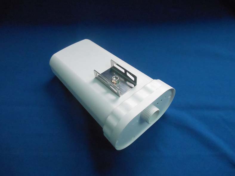
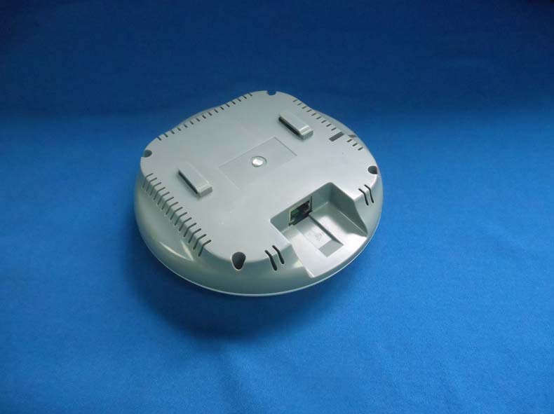
Report No: 1460171R-RFUSP27V00 Page: 194 of 203 Attachement EUT Photograph (1) EUT Photo (2) EUT Photo
ALCON Technology Corporation 2nd floor, No. 480-6, Sec 6, Yen-Ping N. Road, Shih-Lin, Taipei, Taiwan, R.O.C. FCC ID.: 2ACBOACP24 FCC ID AND DoC Label
ALCON Technology Corporation 2nd floor, No. 480-6, Sec 6, Yen-Ping N. Road, Shih-Lin, Taipei, Taiwan, R.O.C. FCC ID.: 2ACBOACP24 FCC ID AND DoC Label The FCC ID and DoC Label will be placed on the equipment as shown in the photograph below. Wireless Ceiling Access Point Model No.: ACP24 FCC ID : 2ACBOACP24 This device complies with Part 15 of the FCC Rules. Operation is subject to the following two conditions: (1) this device may not cause harmful interference and (2) this device must accept any interference received, including interference that may cause undesired operation. S/N: Made in Taiwan Trade name: ALCON Model number.: ACP24
Report No: 1460171R-RFUSP27V00 Page: 195 of 203 (3) EUT Photo (4) EUT Photo Report No: 1460171R-RFUSP27V00 Page: 196 of 203 (5) EUT Photo (6) EUT Photo Report No: 1460171R-RFUSP27V00 Page: 197 of 203 (7) EUT Photo (8) EUT Photo Report No: 1460171R-RFUSP27V00 Page: 198 of 203 (9) EUT Photo (10) EUT Photo Report No: 1460171R-RFUSP27V00 Page: 199 of 203 (11) EUT Photo (12) EUT Photo (ANT) Report No: 1460171R-RFUSP27V00 Page: 200 of 203 (13) EUT Photo (ANT) (14) EUT Photo Report No: 1460171R-RFUSP27V00 Page: 201 of 203 (15) EUT Photo (16) EUT Photo Report No: 1460171R-RFUSP27V00 Page: 202 of 203 (17) EUT Photo (18) EUT Photo Report No: 1460171R-RFUSP27V00 Page: 203 of 203 (19) EUT Photo(MB)
Report No. 1460171R-RF-US-Exp Page: 1 of 4 RF Exposure Evaluation Declaration Product Name :Wireless Ceiling Access Point Model No. :ACP24 FCC ID. :2ACBOACP24 Applicant : ALCON Technology Corporation Address : 2nd floor,No.480-5, Sec 6, Yen-Ping N. Road, Shih-Lin, Taipei, Taiwan R.O.C. Date of Receipt : 2014/06/04 Date of Declaration : 2014/08/15 Report No. : 1460171R-RF-US-Exp Report Version : V1.0 The declaration results relate only to the samples calculated. The declaration shall not be reproduced except in full without the written approval of QuieTek Corporation. Report No. 1460171R-RF-US-Exp Page: 2 of 4 1. RF Exposure Evaluation 1.1. Limits According to FCC 1.1310: The criteria listed in the following table shall be used to evaluate the environment impact of human exposure to radio frequency (RF) radiation as specified in 1.1307(b) LIMITS FOR MAXIMUM PERMISSIBLE EXPOSURE (MPE) Frequency Range (MHz) Electric Field Strength (V/m) Magnetic Field Strength (A/m) Power Density (mW/cm 2 ) Average Time (Minutes) (A) Limits for Occupational/ Control Exposures 300-1500 -- -- F/300 6 1500-100,000 -- -- 5 6 (B) Limits for General Population/ Uncontrolled Exposures 300-1500 -- -- F/1500 6 1500-100,000 -- -- 1 30 F= Frequency in MHz Friis Formula Friis transmission formula: Pd = (Pout*G)/(4*pi*r 2 ) Where Pd = power density in mW/cm 2 Pout = output power to antenna in mW G = gain of antenna in linear scale Pi = 3.1416 R = distance between observation point and center of the radiator in cm Pd id the limit of MPE, 1 mW/cm 2 . If we know the maximum gain of the antenna and the total power input to the antenna, through the calculation, we will know the distance r where the MPE limit is reached. 1.2. Test Procedure Software provided by client enabled the EUT to transmit and receive data at lowest, middle and highest channel individually. The temperature and related humidity: 18°Cand 78% RH. Report No. 1460171R-RF-US-Exp Page: 3 of 4 1.3. Test Result of RF Exposure Evaluation Product Wireless Ceiling Access Point Test Mode Transmit Test Condition RF Exposure Evaluation Antenna Gain Antenna Gain: The maximum Gain measured in fully anechoic chamber is 9dBi or 7.94 in linear scale. Output Power into Antenna & RF Exposure Evaluation Distance: IEEE 802.11b WLAN Function Channel Channel Frequency (MHz) Output Power to Antenna (mW) Power Density at R = 20 cm (mW/cm 2 ) 1 2412 97.0510 0.1534 6 2437 93.7562 0.1482 11 2462 108.1434 0.1709 IEEE 802.11g WLAN Function Channel Channel Frequency (MHz) Output Power to Antenna (mW) Power Density at R = 20 cm (mW/cm 2 ) 1 2412 356.4511 0.5633 6 2437 339.6253 0.5367 11 2462 403.6454 0.6379 The power density Pd (4th column) at a distance of 20 cm calculated from the Friis transmission formula is far below the limit of 1 mW/cm 2 . Report No. 1460171R-RF-US-Exp Page: 4 of 4 Product Wireless Ceiling Access Point Test Mode Transmit Test Condition RF Exposure Evaluation Antenna Gain Antenna Gain: The maximum Gain measured in fully anechoic chamber is 9dBi or 7.94 in linear scale. Output Power into Antenna & RF Exposure Evaluation Distance: IEEE 802.11n (20MHz) ANT 0+1 WLAN Function Channel Channel Frequency (MHz) Output Power to Antenna (mW) Power Density at R = 20 cm (mW/cm 2 ) 1 2412 207.0141 0.3271 6 2437 234.9633 0.3713 11 2462 225.9436 0.3571 IEEE 802.11n (40MHz) ANT 0+1 WLAN Function Channel Channel Frequency (MHz) Output Power to Antenna (mW) Power Density at R = 20 cm (mW/cm 2 ) 3 2422 170.0983 0.2688 6 2437 217.2201 0.3433 9 2452 213.2554 0.3370 The power density Pd (4th column) at a distance of 20 cm calculated from the Friis transmission formula is far below the limit of 1 mW/cm 2 .
Report No: 1460171R-RFUSP27V00 Page: 1 of 203 FCC Test Report Product Name :Wireless Ceiling Access Point Model No. :ACP24 FCC ID. :2ACBOACP24 Applicant : ALCON Technology Corporation Address : 2nd floor,No.480-5, Sec 6, Yen-Ping N. Road, Shih-Lin, Taipei, Taiwan R.O.C. Date of Receipt:2014/06/04 Issued Date :2014/08/15 Report No. :1460171R-RFUSP27V00 Report Version :V1.0 The test results relate only to the samples tested. The test report shall not be reproduced except in full without the written approval of QuieTek Corporation. Report No: 1460171R-RFUSP27V00 Page: 2 of 203 Test Report Certification Issued Date : 2014/08/15 Report No. : 1460171R-RFUSP27V00 Product Name : Wireless Ceiling Access Point Applicant : ALCON Technology Corporation Address : 2nd floor,No.480-5, Sec 6, Yen-Ping N. Road, Shih-Lin, Taipei, Taiwan R.O.C. Manufacturer : ALCON Technology Corporation Model No. : ACP24 FCC ID. : 2ACBOACP24 EUT Test Voltage : DC 48~56V Trade Name : ALCON Applicable Standard : FCC CFR Title 47 Part 15 Subpart C Section 15.247: 2013 ANSI C63.4: 2009 Test Result : Complied The test results relate only to the samples tested. The test report shall not be reproduced except in full without the written approval of QuieTek Corporation. Documented By : ( Demi Chang / Engineering Adm. Specialist ) Reviewed By : ( Bruno Tsai / Assistant Engineer) Approved By : ( Roy Wang / Director ) Report No: 1460171R-RFUSP27V00 Page: 3 of 203 Laboratory Information We, QuieTek Corporation, are an independent RF consultancy that was established the whole facility in our laboratories. The test facility has been accredited/accepted (audited or listed) by the following related bodies in compliance with ISO 17025 specified testing scopes: The related certificate for our laboratories about the test site and management system can be downloaded from QuieTek Corporation’s Web Site:http://www.quietek.com/tw/ctg/cts/accreditations.htm The address and introduction of QuieTek Corporation’s laboratories can be founded in our Web site : http://www.quietek.com/ If you have any comments, Please don’t hesitate to contact us. Our contact information is as below: HsinChu Testing Laboratory: No.75-2, 3rd Lin, Wangye Keng, Yonghxing Tsuen, Qionglin Shiang, Hsinchu County 307, Taiwan, R.O.C. TEL:+886-3-592-8858 / FAX:+886-3-592-8859 E-Mail : [email protected] LinKou Testing Laboratory: No.5-22, Ruishukeng, Linkou Dist., New Taipei City 24451, Taiwan, R.O.C. TEL : 886-2-8601-3788 / FAX : 886-2-8601-3789 E-Mail : [email protected] Taiwan R.O.C. : TAF, Accreditation Number: 1313 NCC, Certificate No : NCC-RCB-07 USA : FCC, Registration Number: 365520 Canada : IC, Submission No: 150981 Report No: 1460171R-RFUSP27V00 Page: 4 of 203 TABLE OF CONTENTS Description Page 1. General Information.............................................................................................................. 6 1.1. EUT Description ............................................................................................................. 6 1.2. Test Mode ..................................................................................................................... 10 1.3. Tested System Details .................................................................................................. 11 1.4. Configuration of tested System .................................................................................... 12 1.5. EUT Exercise Software ................................................................................................ 12 1.6. Test Facility...................................................................................................................13 2. Conducted Emission .......................................................................................................... 14 2.1. Test Equipment............................................................................................................. 14 2.2. Test Setup .................................................................................................................... 14 2.3. Limits ............................................................................................................................ 15 2.4. Test Procedure ............................................................................................................. 15 2.5. Test Specification.......................................................................................................... 15 2.6. Uncertainty ................................................................................................................... 15 2.7. Test Result....................................................................................................................16 2.8. Test Photo .................................................................................................................... 18 3. Peak Power Output ............................................................................................................ 19 3.1. Test Equipment............................................................................................................. 19 3.2. Test Setup .................................................................................................................... 19 3.3. Test procedures ............................................................................................................ 19 3.4. Limits ............................................................................................................................ 19 3.5. Test Specification.......................................................................................................... 19 3.6. Uncertainty ................................................................................................................... 19 3.7. Test Result....................................................................................................................20 4. Radiated Emission ..…
Text truncated - open the document above for the full version.
Report No: 1460171R-RFUSP27V00 Page: 18 of 203 2.8. Test Photo Test Mode : Mode 1: Transmit Description: Front View of Conducted Emission Test Setup Test Mode : Mode 1: Transmit Description: Back View of Conducted Emission Test Setup Report No: 1460171R-RFUSP27V00 Page: 62 of 203 4.8. Test Photo Test Mode : Mode 1: Transmit Description: Front View of Radiated Emission Test Setup (Bi-Log) Test Mode : Mode 1: Transmit Description: Back View of Radiated Emission Test Setup (Bi-Log) Report No: 1460171R-RFUSP27V00 Page: 63 of 203 Test Mode : Mode 1: Transmit Description: Front View of Radiated Emission Test Setup (Horn) Test Mode : Mode 1: Transmit Description: Back View of Radiated Emission Test Setup (Horn)
N0. 75-2, 3rd Lin, Wangye Keng, Yonghxing Tsuen, · Taiwan
| # | Rule Parts | Frequency Range | Power Output |
|---|---|---|---|
| 1 | 15C | 2.41 GHz - 2.46 GHz | 404.00 mW |

Wireless Outdoor Access Point
Equipment Class
DTS - Digital Transmission System