2ACCJB117LTE Mobile WiFi Router
TCL Communication Ltd.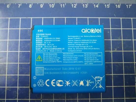
Click to zoom
Application Details
- Equipment Class
- NII - Unlicensed National Information Infrastructure TX
- Date of Grant
- Feb 25, 2020
- Application Purpose
- Original Equipment
- Date of Application
- Feb 25, 2020
- Equipment Note
- LTE Mobile WiFi Router
- Frequency Range
- 5745.00000000 - 5825.00000000
- Company
- TCL Communication Ltd.
- Country
- China
Documents & Files
Document Text
Text extracted from the exhibit documents filed with the FCC. Open a document above to read the original.
Users Manual
Welcome Start Guide P10000243CJB1RL0TBAAA TABLE OF CONTENTS www.sar-tick.com This product meets all applicable national SAR limits of 1.6 W/kg. Maximum SAR values can be found in the radio waves section of included user manual. If device is being worn on your person, please maintain a distance of 10 mm from your body in order to prevent RF exposure. Please note that mobile hotspot may be transmitting even if device is not in use but powered on. Getting to Know Your Mobile Hotspot ..................1 LED Description .......................................................1 Indicators ...................................................................2 Inserting the SIM card .............................................4 Removing the SIM card ...........................................5 Inserting/Removing the battery .............................6 Charging Your Mobile Hotspot ..............................6 Charging other devices ...........................................7 Forgot your password? ............................................7 OS supported ...........................................................8 Connect your Wi-Fi device to your Mobile Hotspot ......................................................................8 Use the WPS .............................................................9 Managing Your Mobile Hotspot ...........................10 Accessing Your Mobile Hotspot ..........................10 Access Using a USB Cable ..................................11 Change Mobile Hotspot Admin Password .........12 Change Mobile Hotspot Network Name (SSID) ...........................................................12 Change Mobile Hotspot Wi-Fi Password ............13 How to use the Mobile Hotspot Whitelist Function ...................................................................13 Updating Your Software Version .........................14 Safety and Use ........................................................16 Conditions of use ...................................................17 Radio Waves ...........................................................21 Licenses ...................................................................26 General Information ...............................................26 12 Month Limited Warranty ..................................27 Electronic Information ...........................................27 12 GETTING TO KNOW YOUR MOBILE HOTSPOT Power key WPS key LED DESCRIPTION PartDescription Power keyHold the Power key for 3 seconds to power the device on/off. WPS keyHold the WPS key for 3 seconds to activate the WPS function. Once activated, the Wi-Fi LED indicator will flash every two seconds. If the network is not accessed within 2 minutes, device will automatically exit WPS mode. LED indicators Displays Wi-Fi, signal, battery, and SMS status. LED indicators Charging out port Charging in port Charging in USB Port Use the USB Type-C port to charge your device and connect your device to the client via the USB cable. Charging out USB port Use the USB port to charge other devices, such as tablets and smartphones. ResetPress Reset key for 3 seconds to reset device. All LED indicators will flash blue 2 times to indicate that the device has been reset to factory mode. RebootHold Power key for 10 seconds to restart device. INDICATORS When the hotspot is powered on, the following icons will illuminate. For a description of the icons, please refer to the table below: Wi-Fi Indicator (Blue LED) Solid Blue Wi-Fi is active. Flashing Blue WPS mode is active. 34 Signal Indicator (Red or Blue LED) Solid Blue Registered and connected to network. Good coverage: 3 LEDs all light up Middle coverage: 2 LEDs light up Weak coverage: 1 LED lights up Flashing Blue Network disconnected. Solid Red No network, no SIM card or SIM card error, limited or no service. Battery Indicator (Red or Blue LED) Solid Blue 3 LEDs light up blue: Battery level 80% - 100% 2 LEDs light up blue: Battery level 40% - 79% 1 LED lights up blue: Battery level 15% - 39% Solid Red 1 LED lights up red: Battery level 0% - 14%. Flashing LEDs will flash while charging. Once the battery level is at 100%, 3 LEDs will display solid blue. SMS Indicator (Blue LED) Solid Blue New message Slowly Flashing Blue Message inbox is full. Off No new messages. Software update Fast Flashing Blue 1. New Software version download or installation is pending. 2. In process of software update installation. INSERTING THE SIM CARD 1. Open the back cover. We suggest that you hold the Alcatel LINKZONE 2 in one hand and put the tip of your thumb of the other hand into the slot and pull the cover outwards to open it. 56 2. Press and push the Nano SIM card to install it in the SIM card slot. REMOVING THE SIM CARD Do not pull the SIM card out forcefully. Press and hold the flat spring, and then pull the SIM card out. INSERTING/REMOVING THE BATTERY Ensure that the pins on the battery are aligned with the pins on the device before fully inserting the battery. Close the back cover with the loopholes aligned. CHARGING YOUR MOBILE HOTSPOT There are two ways to charge your mobile hotspot: 1. Charge using a charger and USB data cable Connect the USB cable into the charging port as shown and connect the charger to a power outlet to start charging. 78 When the device is powered off, it takes about 3 hours before being fully charged. 2. Charge using a computer and USB data cable You can also charge the device by connecting it to a PC with the USB cable. When the device is powered off, it takes about 4 hours to complete charging. Note: When red battery indicator lights up, device should be charged in order to protect the battery. CHARGING OTHER DEVICES Use the full-size USB port to charge other devices, such as tablets and smartphones. FORGOT YOUR PASSWORD? If you forget your password, just reset your device and you will be back up and running in no time. Use a paperclip or blunt pin to gently press the reset button. Reset key OS SUPPORTED…
Text truncated - open the document above for the full version.
Cover Letter(s)
TCL Communication Ltd. 5F, C building, No. 232, Liang Jing Road, ZhangJiang High-Tech Park, Pudong Shanghai, P.R. China. 201203 Tel: +86 21 6146 0666 Fax: +86 21 6146 0602 http://tclcom.tcl.com Date 2020-02-22 To: Federal Communications Commission, Authorization & Evaluation Division, 7345 Oakland Mills Road Columbia, MD 21046 And American Certification Body, Inc. 6731 Whittier Avenue Suite C110 McLean, VA 22101 To Whom It May Concern: CTTL-Telecommunication Technology Labs, Academy of Telecommunication Research, MIIT is authorized to act on our behalf, until otherwise notified, for applications to American Certification Body, Inc. (ACB). We certify that we are not subject to denial of federal benefits, which includes FCC benefits, pursuant to Section 5301 of the Anti-Drug Abuse Act of 1988, U.S.C. 862. Further, no party, as defined in 47 CFR1.2002 (b) to the application is subject to denial of federal benefits, that includes FCC benefits. Thank you. Regards, Zhizhou GONG Product Certification Manager TCL Communication Ltd.
Cover Letter(s)
TCL Communication Ltd. 5F, C building, No. 232, Liang Jing Road, ZhangJiang High-Tech Park, Pudong Shanghai, P.R. China. 201203 Tel: +86 21 6146 0666 Fax: +86 21 6146 0602 http://tclcom.tcl.com 2020-02-22 Federal Communications Commission Office of Engineering and Technology Equipment Authorization Division 7345 Oakland Mills Road Columbia, Maryland 21046 Subject: Permanent Confidentiality request for FCC ID: 2ACCJB117 To Whom It May Concern, Pursuant to sections 0.457 and 0.459 of CFR 47, the applicant requests permanent confidential treatment of the following information accompanying this application: - Block Diagram - Schematics - Operational Description - BOM list/Tune-Up-Procedure The above materials contain trade secrets and proprietary information not customarily released to the public. The public disclosure of these matters might be harmful to the applicant and provide unjustified benefits to its competitors. Yours Sincerely, Zhizhou GONG Product Certification Manager TCL Communication Ltd.
Cover Letter(s)
TCL Communication Ltd. 5F, C building, No. 232, Liang Jing Road, ZhangJiang High-Tech Park, Pudong Shanghai, P.R. China. 201203 Tel: +86 21 6146 0666 Fax: +86 21 6146 0602 http://tclcom.tcl.com 2020-02-22 Federal Communications Commission Office of Engineering and Technology Equipment Authorization Division 7345 Oakland Mills Road Columbia, Maryland 21046 Subject: SHORT-TERM Confidentiality request for FCC ID: 2ACCJB117 To Whom It May Concern, Pursuant to sections 0.457 and 0.459 of CFR 47 and to avoid premature release of sensitive information prior to marketing or release of the product to the public, the applicant requests the following documents contained in this certification application be temporarily withheld from public disclosure for an initial period of 180 days: - External Photos - Internal Photos - Test Setup Photos - User manual The applicant also acknowledges that they will also provide appropriate notice to ACB should either of the following occur: a) if the applicant requires additional 45 days extension periods they will notify ACB with a new request letter at least 7 days prior to the short-term confidentiality expiration date – [Note: up to a maximum of 3 extensions only are allowed], or b) Immediately notify ACB in the event the information regarding the product or the product is made available to the public. ACB will then release the documents listed above for public disclosure pursuant to FCC Public Notice DA 04-1705. Yours Sincerely, Zhizhou GONG Product Certification Manager TCL Communication Ltd.
External Photos
MW43TM External Photos MW43TM MW43TM UC13US UC13US_label TLi043F1 TLi043F1_label USB Cable
Internal Photos
MW43TM Internal Photos
RF Exposure Info
©Copyright. All rights reserved by CTTL. SAR TEST REPORT No. I19Z62252-SEM03 For TCL Communication Ltd. LTE Mobile WiFi Router Model name: MW43TM With Hardware Version: 03 Software Version: MW43_ZZ_02.00_01 FCC ID: 2ACCJB117 Issued Date: 2020-2-26 Note: The test results in this test report relate only to the devices specified in this report. This report shall not be reproduced except in full without the written approval of CTTL. The report must not be used by the client to claim product certification, approval, or endorsement by NVLAP, NIST, or any agency of the U.S.Government. Test Laboratory: CTTL, Telecommunication Technology Labs, CAICT No. 51, Xueyuan Road, Haidian District, Beijing, P. R. China 100191. Tel:+86(0)10-62304633-2512, Fax:+86(0)10-62304633-2504 Email: [email protected], website: www.caict.ac.cn No.I19Z62252-SEM03 ©Copyright. All rights reserved by CTTL. Page 2 of 215 REPORT HISTORY Report Number Revision Issue Date Description I19Z62252-SEM03 Rev.0 2020-1-29 Initial creation of test report I19Z62252-SEM03 Rev.1 2020-2-26 Update the information on section 17 of test report. No.I19Z62252-SEM03 ©Copyright. All rights reserved by CTTL. Page 3 of 215 TABLE OF CONTENT 1 TEST LABORATORY .................................................................................................................... 5 1.1 TESTING LOCATION ........................................................................................................................................ 5 1.2 TESTING ENVIRONMENT ................................................................................................................................. 5 1.3 PROJECT DATA ............................................................................................................................................... 5 1.4 SIGNATURE ..................................................................................................................................................... 5 2 STATEMENT OF COMPLIANCE .................................................................................................. 6 3 CLIENT INFORMATION ................................................................................................................ 7 3.1 APPLICANT INFORMATION .............................................................................................................................. 7 3.2 MANUFACTURER INFORMATION ..................................................................................................................... 7 4 EQUIPMENT UNDER TEST (EUT) AND ANCILLARY EQUIPMENT (AE) ................................. 8 4.1 ABOUT EUT ................................................................................................................................................... 8 4.2 INTERNAL IDENTIFICATION OF EUT USED DURING THE TEST .......................................................................... 8 4.3 INTERNAL IDENTIFICATION OF AE USED DURING THE TEST ............................................................................ 8 5 TEST METHODOLOGY ................................................................................................................ 9 5.1 APPLICABLE LIMIT REGULATIONS .................................................................................................................. 9 5.2 APPLICABLE MEASUREMENT STANDARDS ...................................................................................................... 9 6 SPECIFIC ABSORPTION RATE (SAR) ...................................................................................... 10 6.1 INTRODUCTION ............................................................................................................................................. 10 6.2 SAR DEFINITION .......................................................................................................................................... 10 7 TISSUE SIMULATING LIQUIDS ................................................................................................. 11 7.1 TARGETS FOR TISSUE SIMULATING LIQUID .................................................................................................... 11 7.2 DIELECTRIC PERFORMANCE ......................................................................................................................... 11 8 SYSTEM VERIFICATION ............................................................................................................ 16 8.1 SYSTEM SETUP ............................................................................................................................................. 16 8.2 SYSTEM VERIFICATION ................................................................................................................................. 17 9 MEASUREMENT PROCEDURES .............................................................................................. 18 9.1 TESTS TO BE PERFORMED ............................................................................................................................. 18 9.2 GENERAL MEASUREMENT PROCEDURE ........................................................................................................ 20 9.3 WCDMA MEASUREMENT PROCEDURES FOR SAR ...................................................................................... 21 9.4 SAR MEASUREMENT FOR LTE ..................................................................................................................... 22 9.5 BLUETOOTH & WI-FI MEASUREMENT PROCEDURES FOR SAR .................................................................... 24 9.6 POWER DRIFT ............................................................................................................................................... 24 10 AREA SCAN BASED 1-G SAR ................................................................................................. 25 10.1 REQUIREMENT OF KDB ...........................…
Text truncated - open the document above for the full version.
RF Exposure Info
No.I19Z62252-SEM03 ©Copyright. All rights reserved by CTTL. Page 109 of 215 5750 MHz Date: 1/4/2020 Electronics: DAE4 Sn771 Medium: Head 5750 MHz Medium parameters used: f = 5750 MHz; σ =5.183 mho/m; ε r = 34.96; ρ = 1000 kg/m 3 Ambient Temperature: 22.5 o C Liquid Temperature: 22.3 o C Communication System: CW Frequency: 5750 MHz Duty Cycle: 1:1 Probe: EX3DV4 – SN3617ConvF(5.07,5.07,5.07) System Validation /Area Scan (81x191x1): Interpolated grid: dx=1.000 mm, dy=1.000 mm Maximum value of SAR (interpolated) = 19.14 W/kg System Validation /Zoom Scan (7x7x7)/Cube 0: Measurement grid: dx=5mm, dy=5mm, dz=5mm Reference Value =71.13 V/m; Power Drift = 0.02 dB Peak SAR (extrapolated) = 30.96 W/kg SAR(1 g) = 20.4 W/kg; SAR(10 g) = 5.69 W/kg Maximum value of SAR (measured) = 18.68 W/kg 0 dB = 18.68 W/kg = 12.71 dB W/kg Fig.B.8 validation 5750 MHz 100mW No.I19Z62252-SEM03 ©Copyright. All rights reserved by CTTL. Page 110 of 215 The SAR system verification must be required that the area scan estimated 1-g SAR is within 3% of the zoom scan 1-g SAR. Table B.1 Comparison between area scan and zoom scan for system verification Date Band Position Area scan (1g) Zoom scan (1g) Drift (%) 2020-1-2 750 Head 2.18 2.15 1.40 2020-1-2 835 Head 2.42 2.42 0.00 2020-1-3 1750 Head 9.03 8.99 0.44 2020-1-3 1900 Head 10.02 9.73 2.98 2020-1-4 2450 Head 12.68 12.9 -1.71 2020-1-4 2600 Head 13.95 14.11 -1.13 No.I19Z62252-SEM03 ©Copyright. All rights reserved by CTTL. Page 111 of 215 ANNEX C SAR Measurement Setup C.1 Measurement Set-up The Dasy4 or DASY5 system for performing compliance tests is illustrated above graphically. This system consists of the following items: Picture C.1SAR Lab Test Measurement Set-up ⚫ A standard high precision 6-axis robot (StäubliTX=RX family) with controller, teach pendant and software. An arm extension for accommodating the data acquisition electronics (DAE). ⚫ An isotropic field probe optimized and calibrated for the targeted measurement. ⚫ A data acquisition electronics (DAE) which performs the signal amplification, signal multiplexing, AD-conversion, offset measurements, mechanical surface detection, collision detection, etc. The unit is battery powered with standard or rechargeable batteries. The signal is optically transmitted to the EOC. ⚫ The Electro-optical converter (EOC) performs the conversion from optical to electrical signals for the digital communication to the DAE. To use optical surface detection, a special version of the EOC is required. The EOC signal is transmitted to the measurement server. ⚫ The function of the measurement server is to perform the time critical tasks such as signal filtering, control of the robot operation and fast movement interrupts. ⚫ The Light Beam used is for probe alignment. This improves the (absolute) accuracy of the probe positioning. ⚫ A computer running WinXP and the DASY4 or DASY5 software. ⚫ Remote control and teach pendant as well as additional circuitry for robot safety such as ⚫ warning lamps, etc. ⚫ The phantom, the device holder and other accessories according to the targeted measurement. No.I19Z62252-SEM03 ©Copyright. All rights reserved by CTTL. Page 112 of 215 C.2 Dasy4 or DASY5 E-field Probe System The SAR measurements were conducted with the dosimetric probe designed in the classical triangular configuration and optimized for dosimetric evaluation. The probe is constructed using the thick film technique; with printed resistive lines on ceramic substrates. The probe is equipped with an optical multifiber line ending at the front of the probe tip. It is connected to the EOC box on the robot arm and provides an automatic detection of the phantom surface. Half of the fibers are connected to a pulsed infrared transmitter, the other half to a synchronized receiver. As the probe approaches the surface, the reflection from the surface produces a coupling from the transmitting to the receiving fibers. This reflection increases first during the approach, reaches maximum and then decreases. If the probe is flatly touching the surface, the coupling is zero. The distance of the coupling maximum to the surface is independent of the surface reflectivity and largely independent of the surface to probe angle. The DASY4 or DASY5 software reads the reflection durning a software approach and looks for the maximum using 2 nd ord curve fitting. The approach is stopped at reaching the maximum. Probe Specifications: Model: ES3DV3, EX3DV4 Frequency 10MHz — 6.0GHz(EX3DV4) Range: 10MHz — 4GHz(ES3DV3) Calibration: In head and body simulating tissue at Frequencies from 835 up to 5800MHz Linearity: ± 0.2 dB(30 MHz to 6 GHz) for EX3DV4 Picture C.2Near-field Probe ± 0.2 dB(30 MHz to 4 GHz) for ES3DV3 DynamicRange: 10 mW/kg — 100W/kg Probe Length: 330 mm Probe Tip Length: 20 mm Body Diameter: 12 mm Tip Diameter: 2.5 mm (3.9 mm for ES3DV3) Tip-Center: 1 mm (2.0mm for ES3DV3) Application:SAR Dosimetry Testing Compliance tests ofmobile phones Dosimetry in strong gradient fields Picture C.3E-field Probe C.3 E-field Probe Calibration Each E-Probe/Probe Amplifier combination has unique calibration parameters. A TEM cell calibration procedure is conducted to determine the proper amplifier settings to enter in the probe parameters. The amplifier settings are determined for a given frequency by subjecting the probe to a known E-field density (1 mW/cm 2 ) using an RF Signal generator, TEM cell, and RF Power Meter. The free space E-field from amplified probe outputs is determined in a test chamber. This calibration can be performed in a TEM cell if the frequency is below 1 GHz and inn a waveguide or No.I19Z62252-SEM03 ©Copyright. All rights reserved by CTTL. Page 113 of 215 other methodologies above 1 GHz for free space. For the free space calibration, the probe is placed in the volumetric center of the cavity and at the proper orientation with the field. The probe is then rotated 360 degrees until the three channels show the maximum reading. The power density readings equ…
Text truncated - open the document above for the full version.
RF Exposure Info
No.I19Z62252-SEM03 ©Copyright. All rights reserved by CTTL. Page 118 of 215 Picture D.5 Test positions for desktop devices D.3 DUT Setup Photos Picture D.6 No.I19Z62252-SEM03 ©Copyright. All rights reserved by CTTL. Page 119 of 215 ANNEX E Equivalent Media Recipes The liquid used for the frequency range of 800-3000 MHz consisted of water, sugar, salt, preventol, glycol monobutyl and Cellulose. The liquid has been previously proven to be suited for worst-case. The Table E.1 shows the detail solution. It’s satisfying the latest tissue dielectric parameters requirements proposed by the IEEE 1528 and IEC 62209. TableE.1: Composition of the Tissue Equivalent Matter Frequency (MHz) 835Head 835Body 1900 Head 1900 Body 2450 Head 2450 Body 5800 Head 5800 Body Ingredients (% by weight) Water 41.45 52.5 55.242 69.91 58.79 72.60 65.53 65.53 Sugar 56.0 45.0 \ \ \ \ \ \ Salt 1.45 1.4 0.306 0.13 0.06 0.18 \ \ Preventol 0.1 0.1 \ \ \ \ \ \ Cellulose 1.0 1.0 \ \ \ \ \ \ Glycol Monobutyl \ \ 44.452 29.96 41.15 27.22 \ \ Diethylenglycol monohexylether \ \ \ \ \ \ 17.24 17.24 Triton X-100 \ \ \ \ \ \ 17.24 17.24 Dielectric Parameters Target Value ε=41.5 σ=0.90 ε=55.2 σ=0.97 ε=40.0 σ=1.40 ε=53.3 σ=1.52 ε=39.2 σ=1.80 ε=52.7 σ=1.95 ε=35.3 σ=5.27 ε=48.2 σ=6.00 Note: There are a little adjustment respectively for 750, 1750, 2600, 5200, 5300 and 5600 based on the recipe of closest frequency in table E.1. No.I19Z62252-SEM03 ©Copyright. All rights reserved by CTTL. Page 120 of 215 ANNEX F System Validation The SAR system must be validated against its performance specifications before it is deployed. When SAR probes, system components or software are changed, upgraded or recalibrated, these must be validated with the SAR system(s) that operates with such components. Table F.1: System Validation for 3617 Probe SN. Liquid name Validation date Frequency point Status (OK or Not) 3617 Head 750MHz Feb.14,2019 750 MHz OK 3617 Head 850MHz Feb.14,2019 835 MHz OK 3617 Head 900MHz Feb.14,2019 900 MHz OK 3617 Head 1750MHz Feb.14,2019 1750 MHz OK 3617 Head 1810MHz Feb.14,2019 1810 MHz OK 3617 Head 1900MHz Feb.15,2019 1900 MHz OK 3617 Head 2000MHz Feb.15,2019 2000 MHz OK 3617 Head 2100MHz Feb.15,2019 2100 MHz OK 3617 Head 2300MHz Feb.15,2019 2300 MHz OK 3617 Head 2450MHz Feb.15,2019 2450 MHz OK 3617 Head 2600MHz Feb.16,2019 2600 MHz OK 3617 Head 3500MHz Feb.16,2019 3500 MHz OK 3617 Head 3700MHz Feb.16,2019 3700 MHz OK 3617 Head 5200MHz Feb.16,2019 5250 MHz OK 3617 Head 5500MHz Feb.16,2019 5600 MHz OK 3617 Head 5800MHz Feb.16,2019 5800 MHz OK 3617 Body 750MHz Feb.16,2019 750 MHz OK 3617 Body 850MHz Feb.13,2019 835 MHz OK 3617 Body 900MHz Feb.13,2019 900 MHz OK 3617 Body 1750MHz Feb.13,2019 1750 MHz OK 3617 Body 1810MHz Feb.13,2019 1810 MHz OK 3617 Body 1900MHz Feb.13,2019 1900 MHz OK 3617 Body 2000MHz Feb.17,2019 2000 MHz OK 3617 Body 2100MHz Feb.17,2019 2100 MHz OK 3617 Body 2300MHz Feb.17,2019 2300 MHz OK 3617 Body 2450MHz Feb.17,2019 2450 MHz OK 3617 Body 2600MHz Feb.17,2019 2600 MHz OK 3617 Body 3500MHz Feb.12,2019 3500 MHz OK 3617 Body 3700MHz Feb.12,2019 3700 MHz OK 3617 Body 5200MHz Feb.12,2019 5250 MHz OK 3617 Body 5500MHz Feb.12,2019 5600 MHz OK 3617 Body 5800MHz Feb.12,2019 5800 MHz OK No.I19Z62252-SEM03 ©Copyright. All rights reserved by CTTL. Page 121 of 215 ANNEX G Probe Calibration Certificate Probe 3617 Calibration Certificate No.I19Z62252-SEM03 ©Copyright. All rights reserved by CTTL. Page 122 of 215 No.I19Z62252-SEM03 ©Copyright. All rights reserved by CTTL. Page 123 of 215 No.I19Z62252-SEM03 ©Copyright. All rights reserved by CTTL. Page 124 of 215 No.I19Z62252-SEM03 ©Copyright. All rights reserved by CTTL. Page 125 of 215 No.I19Z62252-SEM03 ©Copyright. All rights reserved by CTTL. Page 126 of 215
RF Exposure Info
No.I19Z62252-SEM03 ©Copyright. All rights reserved by CTTL. Page 127 of 215 No.I19Z62252-SEM03 ©Copyright. All rights reserved by CTTL. Page 128 of 215 No.I19Z62252-SEM03 ©Copyright. All rights reserved by CTTL. Page 129 of 215 No.I19Z62252-SEM03 ©Copyright. All rights reserved by CTTL. Page 130 of 215 No.I19Z62252-SEM03 ©Copyright. All rights reserved by CTTL. Page 131 of 215 No.I19Z62252-SEM03 ©Copyright. All rights reserved by CTTL. Page 132 of 215 No.I19Z62252-SEM03 ©Copyright. All rights reserved by CTTL. Page 133 of 215 No.I19Z62252-SEM03 ©Copyright. All rights reserved by CTTL. Page 134 of 215 No.I19Z62252-SEM03 ©Copyright. All rights reserved by CTTL. Page 135 of 215
RF Exposure Info
No.I19Z62252-SEM03 ©Copyright. All rights reserved by CTTL. Page 136 of 215 No.I19Z62252-SEM03 ©Copyright. All rights reserved by CTTL. Page 137 of 215 No.I19Z62252-SEM03 ©Copyright. All rights reserved by CTTL. Page 138 of 215 No.I19Z62252-SEM03 ©Copyright. All rights reserved by CTTL. Page 139 of 215 No.I19Z62252-SEM03 ©Copyright. All rights reserved by CTTL. Page 140 of 215 ANNEX H Dipole Calibration Certificate 750 MHz Dipole Calibration Certificate No.I19Z62252-SEM03 ©Copyright. All rights reserved by CTTL. Page 141 of 215 No.I19Z62252-SEM03 ©Copyright. All rights reserved by CTTL. Page 142 of 215 No.I19Z62252-SEM03 ©Copyright. All rights reserved by CTTL. Page 143 of 215 No.I19Z62252-SEM03 ©Copyright. All rights reserved by CTTL. Page 144 of 215
RF Exposure Info
No.I19Z62252-SEM03 ©Copyright. All rights reserved by CTTL. Page 145 of 215 No.I19Z62252-SEM03 ©Copyright. All rights reserved by CTTL. Page 146 of 215 No.I19Z62252-SEM03 ©Copyright. All rights reserved by CTTL. Page 147 of 215 No.I19Z62252-SEM03 ©Copyright. All rights reserved by CTTL. Page 148 of 215 835 MHz Dipole Calibration Certificate No.I19Z62252-SEM03 ©Copyright. All rights reserved by CTTL. Page 149 of 215 No.I19Z62252-SEM03 ©Copyright. All rights reserved by CTTL. Page 150 of 215 No.I19Z62252-SEM03 ©Copyright. All rights reserved by CTTL. Page 151 of 215 No.I19Z62252-SEM03 ©Copyright. All rights reserved by CTTL. Page 152 of 215 No.I19Z62252-SEM03 ©Copyright. All rights reserved by CTTL. Page 153 of 215
RF Exposure Info
No.I19Z62252-SEM03 ©Copyright. All rights reserved by CTTL. Page 154 of 215 No.I19Z62252-SEM03 ©Copyright. All rights reserved by CTTL. Page 155 of 215 No.I19Z62252-SEM03 ©Copyright. All rights reserved by CTTL. Page 156 of 215 1750 MHz Dipole Calibration Certificate No.I19Z62252-SEM03 ©Copyright. All rights reserved by CTTL. Page 157 of 215 No.I19Z62252-SEM03 ©Copyright. All rights reserved by CTTL. Page 158 of 215 No.I19Z62252-SEM03 ©Copyright. All rights reserved by CTTL. Page 159 of 215 No.I19Z62252-SEM03 ©Copyright. All rights reserved by CTTL. Page 160 of 215 No.I19Z62252-SEM03 ©Copyright. All rights reserved by CTTL. Page 161 of 215 No.I19Z62252-SEM03 ©Copyright. All rights reserved by CTTL. Page 162 of 215
RF Exposure Info
No.I19Z62252-SEM03 ©Copyright. All rights reserved by CTTL. Page 163 of 215 No.I19Z62252-SEM03 ©Copyright. All rights reserved by CTTL. Page 164 of 215 1900 MHz Dipole Calibration Certificate No.I19Z62252-SEM03 ©Copyright. All rights reserved by CTTL. Page 165 of 215 No.I19Z62252-SEM03 ©Copyright. All rights reserved by CTTL. Page 166 of 215 No.I19Z62252-SEM03 ©Copyright. All rights reserved by CTTL. Page 167 of 215 No.I19Z62252-SEM03 ©Copyright. All rights reserved by CTTL. Page 168 of 215 No.I19Z62252-SEM03 ©Copyright. All rights reserved by CTTL. Page 169 of 215 No.I19Z62252-SEM03 ©Copyright. All rights reserved by CTTL. Page 170 of 215 No.I19Z62252-SEM03 ©Copyright. All rights reserved by CTTL. Page 171 of 215 No.I19Z62252-SEM03 ©Copyright. All rights reserved by CTTL. Page 172 of 215 2450 MHz Dipole Calibration Certificate No.I19Z62252-SEM03 ©Copyright. All rights reserved by CTTL. Page 173 of 215 No.I19Z62252-SEM03 ©Copyright. All rights reserved by CTTL. Page 174 of 215 No.I19Z62252-SEM03 ©Copyright. All rights reserved by CTTL. Page 175 of 215 No.I19Z62252-SEM03 ©Copyright. All rights reserved by CTTL. Page 176 of 215
RF Exposure Info
No.I19Z62252-SEM03 ©Copyright. All rights reserved by CTTL. Page 177 of 215 No.I19Z62252-SEM03 ©Copyright. All rights reserved by CTTL. Page 178 of 215 No.I19Z62252-SEM03 ©Copyright. All rights reserved by CTTL. Page 179 of 215 No.I19Z62252-SEM03 ©Copyright. All rights reserved by CTTL. Page 180 of 215 2600 MHz Dipole Calibration Certificate No.I19Z62252-SEM03 ©Copyright. All rights reserved by CTTL. Page 181 of 215 No.I19Z62252-SEM03 ©Copyright. All rights reserved by CTTL. Page 182 of 215 No.I19Z62252-SEM03 ©Cop…
Text truncated - open the document above for the full version.
Contact Information
Applicant
Annie Jiang
Technical Contact
Telecommunications Technology Labs, CAICTXue Zhen
[email protected]861062304633
No. 52, Huayuan Bei Road, Haidian District, · China
Test Firm
Telecommunication Technology Labs, CAICTYaqin Shen
Technical Specifications
| # | Rule Parts | Frequency Range | Power Output |
|---|---|---|---|
| 2 | 15E | 5.75 GHz - 5.83 GHz | 42.70 mW |
Other Applications from TCL Communication Ltd.
2ACCJSCD002
Sep 10, 2024USB Connect 5G (NA)
Equipment Class
CXX - Communications Rcvr for use w/ licensed Tx and CBs2ACCJB227
Aug 21, 2024Smart phone
Equipment Class
DTS - Digital Transmission System2ACCJSCD005
Aug 07, 2024TCL LINKPORT IK511
Equipment Class
CXX - Communications Rcvr for use w/ licensed Tx and CBs2ACCJB224
Jul 31, 2024Tablet PC
Equipment Class
DSS - Part 15 Spread Spectrum Transmitter2ACCJB223
Jun 27, 2024Tablet PC
Equipment Class
NII - Unlicensed National Information Infrastructure TX