2ACCJB207Tablet PC
TCL Communication Ltd.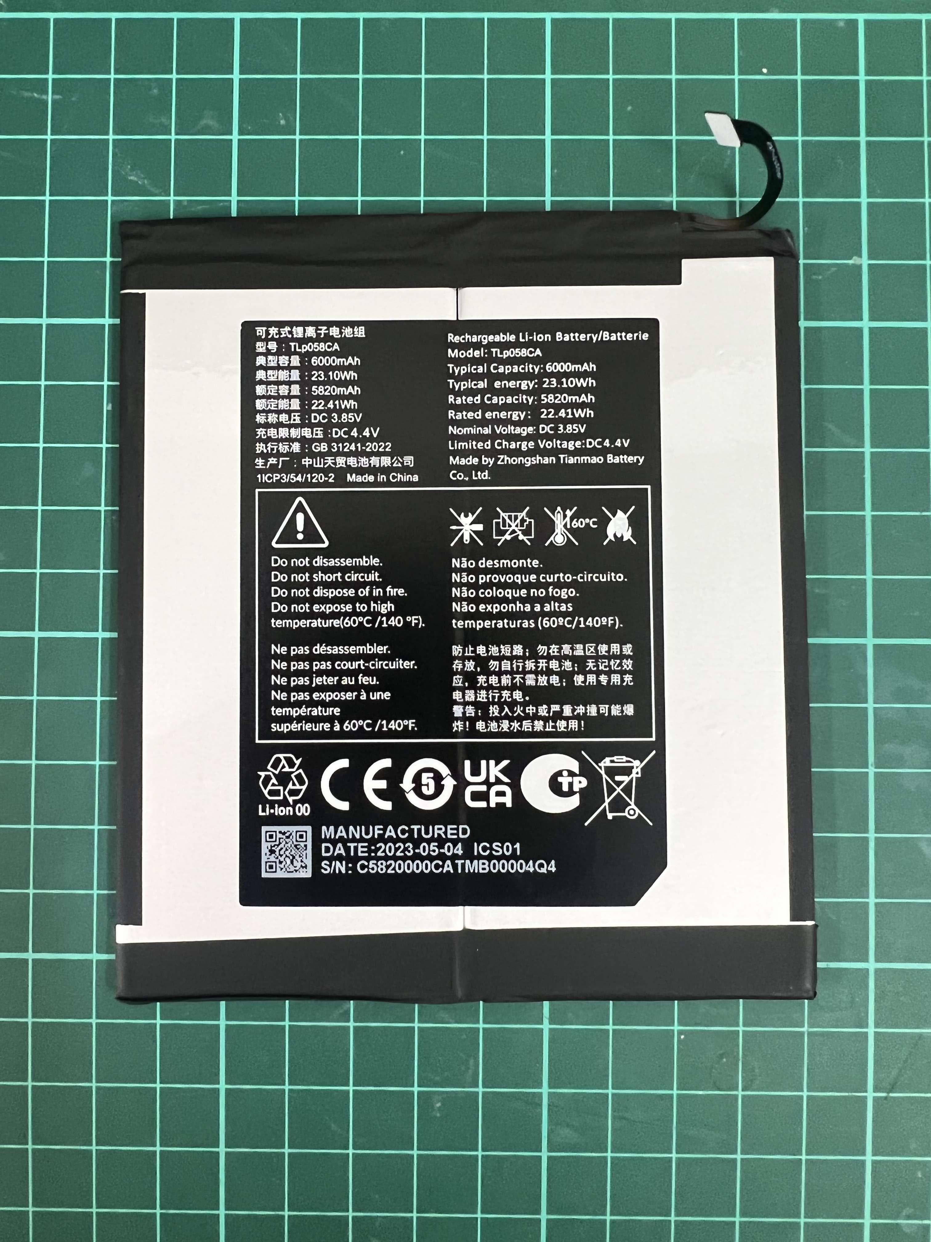
Click to zoom
Application Details
- Equipment Class
- DSS - Part 15 Spread Spectrum Transmitter
- Date of Grant
- Jul 06, 2023
- Application Purpose
- Original Equipment
- Date of Application
- Jul 05, 2023
- Equipment Note
- Tablet PC
- Frequency Range
- 2402.00000000 - 2480.00000000
- Company
- TCL Communication Ltd.
- Country
- China
Documents & Files
Document Text
Text extracted from the exhibit documents filed with the FCC. Open a document above to read the original.
Users Manual
User manual www.tcl.com/mx Quick Start Guide Printed in China XXX 1 2 Help • Update your device's software Go to Settings > System > System Update to check software updates. • Back up your personal data Go to Settings > System > Backup > Back up to Google Drive and turn it on. • Reset your device Go to Settings > System > Reset options > Erase all data (factory reset), and then touch to reset your Device. • Electronic labeling path Touch Settings > System > Regulatory & safety to find more information about labeling (1) , such as FCC ID. General Information • Manufacturer: TCL Communication Ltd. • Address: Av. Adolfo López Mateos Sur 4175, La Giralda, 45088 Zapopan, Jal. • Visit the TCL website at https://www.tcl.com/mx for tutorials and answers to frequently asked questions, and to download the User Manual. • To get support for your device, visit the TCL website (https://www.tcl.com/mx/es/service-support-mobile.html), or dial the number listed below: Argentina: 0810-999-1099 Chile: +56 22 958 96 94 Colombia: 18009520823 Ecuador: 800000635 Mexico: 8008909908 Peru: 080000698 The Dominican Republic: 8887600164 Uruguay: +598 2908 7003 Venezuela: 08001005368 (1) This may vary depending on country. 3 Safety and use Please read this chapter carefully before using your device. The manufacturer disclaims any liability for damage, which may result as a consequence of improper use or use contrary to the instructions contained herein. • Do not use your device when the vehicle is not safely parked. Using a hand-held device while driving is illegal in many countries. • Comply with restrictions on use specific to certain places (hospitals, planes, gas stations, schools, etc.). • Switch the device off before boarding an aircraft. • Switch the device off when you are in health care facilities, except in designated areas. • Switch the device off when you are near gas or flammable liquids. Strictly obey all signs and instructions posted in a fuel depot, petrol station, or chemical plant, or in any potentially explosive atmosphere when operate your device. • Turn off your mobile device or wireless device when in a blasting area or in areas posted with notifications requesting "two-way radios" or "electronic devices" are turned off to avoid interfering with blasting operations. Please consult your doctor and the device manufacturer to determine if operation of your device may interfere with the operation of your medical device. When the device is switched on, it should be kept at least 15 cm from any medical device such as a pacemaker, a hearing aid, or an insulin pump, etc. • Do not let children use the device and/or play with the device and accessories without supervision. • To reduce exposure to radio waves, it is recommended: - Keep the device away from the belly of pregnant women or the lower abdomen of adolescents. • Do not allow your device to be exposed to adverse weather or environmental conditions (moisture, humidity, rain, infiltration of liquids, dust, sea air, etc.). The manufacturer’s recommended operating temperature range is 0°C (32°F) to 40°C (104°F). At over 40°C (104°F) the legibility of the device’s display may be impaired, though this is temporary and not serious. • Use only batteries, battery chargers, and accessories which are compatible with your device model. • Do not use a damaged device, such as a device with a cracked display or badly dented back cover, as it may cause injury or harm. • Do not keep device connected to charger with battery fully charged for a long period of time as it can cause overheating and shorten battery life. • Do not sleep with the device on your person or in your bed. Do not place the device under a blanket, pillow, or under your body, specially when connected to the charger, as this may cause the device to overheat. 4 PROTECT YOUR HEARING To prevent possible hearing damage, do not listen at high volume levels for long periods. Exercise caution when holding your device near your ear while the loudspeaker is in use. Battery: In accordance with air regulations, the battery of your product is not fully charged. Please charge it first. - Do not attempt to open the battery (due to the risk of toxic fumes and burns). - For a device with a non-removable battery, do not attempt to eject or replace the battery. - Do not puncture, disassemble, or cause a short circuit in a battery. - For a unibody device, do not attempt to open or puncture the back cover. - Do not burn or dispose of a used battery or device in household rubbish or store it at temperatures above 60°C (140°F), this can result in an explosion or the leakage of flammable liquid or gas. Similarly, subjecting the battery to extremely low air pressure may result in an explosion or the leakage of flammable liquid or gas. Only use the battery for the purpose for which it was designed and recommended. Never use damaged batteries. CAUTION: RISK OF EXPLOSION IF BATTERY IS REPLACED BY AN INCORRECT TYPE. DISPOSE OF USED BATTERIES ACCORDING TO THE INSTRUCTIONS. Device, accessory and battery must be disposed of in accordance with locally applicable environmental regulations. This symbol on your device, the battery, and the accessories means that these products must be taken to collection points at the end of their life: • Municipal waste disposal centers with specific bins for these types of equipment; • Collection bins at points of sale. They will then be recycled, preventing substances being disposed of in the environment, so that their components can be reused. Chargers: Home A.C./ Travel chargers will operate within the temperature range of: 0°C (32°F) to 40°C (104°F). The chargers designed for your device meet the standard for safety of information technology equipment and office equipment use. Due to different applicable electrical specifications, a charger you purchased in one jurisdiction may not work in another jurisdiction. They should be used for this purpose only. Characteristics of power supply (depend…
Text truncated - open the document above for the full version.
Attestation Statements
021423-17 rev 4 Certification Application Attestation Statements Date: June 29, 2023 American Certification Body, Inc. 313 Park Avenue Suite 300 Falls Church, VA 22046 To Whom It May Concern: FCC ID: 2ACCJB207 Statement for 47 CFR section 2.911(d)(5)(i) _TCL Communication Ltd._ certifies that as of the date of the application the equipment for which authorization is sought is not “covered” equipment 1 prohibited from receiving an equipment authorization pursuant to section 2.903 of the FCC rules. If the equipment for which the applicant seeks authorization is produced by any of the entities identified on the current Covered List, including affiliates or subsidiaries of the named companies, the applicant must include an explanation on why the equipment is not “covered” equipment. Additional Explanation: <N/A> Statement for 47 CFR section 2.911(d)(5)(ii) __TCL Communication Ltd.__ (“the applicant”) certifies that, as of the date of the filing of this application, the applicant ☐ - is / ☑- is not identified on the Covered List as an entity producing “covered” equipment. Thank you, By: __________________________ _Annie Jiang__ (Signature 2 ) (Print name) Title: __Product Certification Manager_ Company: ____ TCL Communication Ltd._ Telephone: __+8675536611621_____ 1 - The Commission’s Covered List is published by the Public Safety and Homeland Security Bureau and posted on the Commission’s website. This Covered List, which is periodically updated, identifies particular equipment, produced by particular entities, that constitutes “covered” equipment. https://www.fcc.gov/supplychain/coveredlist . 2 - Letters should be placed on appropriate letterhead.
Attestation Statements
TCT Mobile, Inc. 189 Technology Drive, Irvine, California USA 92618 TCT Mobile, Inc. 189 Technology Drive, Irvine, CA 92618 U.S. Agent Designation for Service of Process (Applicant and U.S. Agent are Separate Parties) TO: American Certification Body, Inc. 313 Park Avenue Suite 300 Falls Church, VA 22046 ATTENTION: FCC Certification – Section 2.911(d)(7) Information Designated U.S. Agent Company Name: TCT Mobile (US) Inc. Contact Name: Yao Dai Street Address: 189 Technology Drive City/Province/Zip: Irvine, CA 92618 Telephone No: 1-855-368-0829 Email: [email protected] FRN#: 0033429465 This letter is to confirm that we (“the Designated U.S. Agent) have accepted the responsibility to act as the Designated U.S. Agent for Service of Process as required by section 47 CFR 2.911(d)(7) on behalf of the Applicant noted below. U.S. Agent Signature: Date: Signed by (Printed Name/Title): The Applicant acknowledges that they must maintain an agent for no less than one year after terminating all marketing and importation OR the conclusion of any Commission-related proceeding involving the equipment. The applicant further acknowledges their responsibility to inform the FCC whenever the Designated U.S. Agent information above changes. DocuSign Envelope ID: 988543A9-E4AE-4188-B1BF-74A6C860EF4B Technical Acceptance Manager June 2, 2023 Yao Dai TCT Mobile, Inc. 189 Technology Drive, Irvine, California USA 92618 TCT Mobile, Inc. 189 Technology Drive, Irvine, CA 92618 Applicant Company name: TCL Communication Ltd Grantee Code: 2ACCJ Contact Name: Annie Jiang Street Address: 5/F, Building 22E, 22 Science Park East Avenue, Hong Kong Science Park, Shatin, NT, Hong Kong City/Province/Zip: Hongkong Telephone No: +86 755 36611621 Applicant Signature 1 : Date: Signed by (Printed Name/Title): 1 - Letters should be placed on appropriate letterhead. DocuSign Envelope ID: 988543A9-E4AE-4188-B1BF-74A6C860EF4B Annie Jiang 2023年6月2日 Minister of R&D Platform Dept.
Cover Letter(s)
TCL Communication Ltd. 5/F, Building 22E, 22 Science Park East Avenue, Hong Kong Science Park, Shatin, NT, Hong Kong Tel: +86 755 3664 5759 Fax: +86 755 3661 2000-81722 http://tclcom.tcl.com Date 2023-06-29 To: Federal Communications Commission, Authorization & Evaluation Division, 7345 Oakland Mills Road Columbia, MD 21046 And American Certification Body, Inc. 6731 Whittier Avenue Suite C110 McLean, VA 22101 To Whom It May Concern: CTTL-Telecommunication Technology Labs, Academy of Telecommunication Research, MIIT is authorized to act on our behalf, until otherwise notified, for applications to American Certification Body, Inc. (ACB). We certify that we are not subject to denial of federal benefits, which includes FCC benefits, pursuant to Section 5301 of the Anti-Drug Abuse Act of 1988, U.S.C. 862. Further, no party, as defined in 47 CFR1.2002 (b) to the application is subject to denial of federal benefits, that includes FCC benefits. Thank you. Regards, Annie Jiang Product Certification Manager TCL Communication Ltd.
Cover Letter(s)
TCL Communication Ltd. 5/F, Building 22E, 22 Science Park East Avenue, Hong Kong Science Park, Shatin, NT, Hong Kong Tel: +86 755 3664 5759 Fax: +86 755 3661 2000-81722 http://tclcom.tcl.com 2023-06-29 Federal Communications Commission Office of Engineering and Technology Equipment Authorization Division 7345 Oakland Mills Road Columbia, Maryland 21046 Subject: Permanent Confidentiality request for FCC ID: 2ACCJB207 To Whom It May Concern, Pursuant to sections 0.457 and 0.459 of CFR 47, the applicant requests permanent confidential treatment of the following information accompanying this application: - Block Diagram - Schematics - Operational Description - BOM list/Tune-Up-Procedure The above materials contain trade secrets and proprietary information not customarily released to the public. The public disclosure of these matters might be harmful to the applicant and provide unjustified benefits to its competitors. Yours Sincerely, Annie Jiang Product Certification Manager TCL Communication Ltd.
Cover Letter(s)
TCL Communication Ltd. 5/F, Building 22E, 22 Science Park East Avenue, Hong Kong Science Park, Shatin, NT, Hong Kong Tel: +86 755 3664 5759 Fax: +86 755 3661 2000-81722 http://tclcom.tcl.com 2023-06-29 Federal Communications Commission Office of Engineering and Technology Equipment Authorization Division 7345 Oakland Mills Road Columbia, Maryland 21046 Subject: SHORT-TERM Confidentiality request for FCC ID: 2ACCJB207 To Whom It May Concern, Pursuant to sections 0.457 and 0.459 of CFR 47 and to avoid premature release of sensitive information prior to marketing or release of the product to the public, the applicant requests the following documents contained in this certification application be temporarily withheld from public disclosure for an initial period of 180 days: - External Photos - Internal Photos - Test Setup Photos - User manual The applicant also acknowledges that they will also provide appropriate notice to ACB should either of the following occur: a) if the applicant requires additional 45 days extension periods they will notify ACB with a new request letter at least 7 days prior to the short-term confidentiality expiration date – [Note: up to a maximum of 3 extensions only are allowed], or b) Immediately notify ACB in the event the information regarding the product or the product is made available to the public. ACB will then release the documents listed above for public disclosure pursuant to FCC Public Notice DA 04-1705. Yours Sincerely, Annie Jiang Product Certification Manager TCL Communication Ltd.
External Photos
8492A DataCable : JWUB1591-J51R Charger:CG10A0502000UU Charger:CG10A0502000EU Battery:2853B7PL-2P Battery:TLp058CA
ID Label/Location Info
Label area 50X40mm Freyr_label area_2D_20230625
ID Label/Location Info
FCCLabel E-Label
Internal Photos
8492AInternalphotos
RF Exposure Info
No.I23Z60957-SEM02 ©Copyright. All rights reserved by CTTL. Page 1 of 77 SAR TEST REPORT No. I23Z60957-SEM02 For TCL Communication Ltd. Tablet PC Model Name: 8492A with Hardware Version: 05 Software Version: KZ12 FCC ID: 2ACCJB207 Issued Date: 2023-07-04 Note: The test results in this test report relate only to the devices specified in this report. This report shall not be reproduced except in full without the written approval of CTTL. The report must not be used by the client to claim product certification, approval, or endorsement by NVLAP, NIST, or any agency of the U.S.Government. Test Laboratory: CTTL, Telecommunication Technology Labs, CAICT No. 52, Huayuan North Road, Haidian District, Beijing, P. R. China 100191. Tel:+86(0)10-62304633-2512, Fax:+86(0)10-62304633-2504 Email: [email protected], website: www.caict.ac.cn No.I23Z60957-SEM02 ©Copyright. All rights reserved by CTTL. Page 2 of 77 REPORT HISTORY Report Number Revision Issue Date Description I23Z60957-SEM02 Rev.0 2023-06-28 Initial creation of test report I23Z60957-SEM02 Rev.1 2023-07-04 Update the channel number of WLAN 2.4G in section 10 on page 18&19 No.I23Z60957-SEM02 ©Copyright. All rights reserved by CTTL. Page 3 of 77 TABLE OF CONTENT 1 TEST LABORATORY .................................................................................................................... 5 1.1 TESTING LOCATION ........................................................................................................................................ 5 1.2 TESTING ENVIRONMENT ................................................................................................................................. 5 1.3 PROJECT DATA ............................................................................................................................................... 5 1.4 SIGNATURE ..................................................................................................................................................... 5 2 STATEMENT OF COMPLIANCE .................................................................................................. 6 3 CLIENT INFORMATION ................................................................................................................ 7 3.1 APPLICANT INFORMATION .............................................................................................................................. 7 3.2 MANUFACTURER INFORMATION ..................................................................................................................... 7 4 EQUIPMENT UNDER TEST (EUT) AND ANCILLARY EQUIPMENT (AE) ................................. 8 4.1 ABOUT EUT ................................................................................................................................................... 8 4.2 INTERNAL IDENTIFICATION OF EUT USED DURING THE TEST .......................................................................... 8 4.3 INTERNAL IDENTIFICATION OF AE USED DURING THE TEST ............................................................................ 8 5 TEST METHODOLOGY ................................................................................................................ 9 5.1 APPLICABLE LIMIT REGULATIONS .................................................................................................................. 9 5.2 APPLICABLE MEASUREMENT STANDARDS ...................................................................................................... 9 6 SPECIFIC ABSORPTION RATE (SAR) ...................................................................................... 10 6.1 INTRODUCTION ............................................................................................................................................. 10 6.2 SAR DEFINITION .......................................................................................................................................... 10 7 TISSUE SIMULATING LIQUIDS ................................................................................................. 11 7.1 TARGETS FOR TISSUE SIMULATING LIQUID .................................................................................................... 11 7.2 DIELECTRIC PERFORMANCE ......................................................................................................................... 11 8 SYSTEM VERIFICATION ............................................................................................................ 12 8.1 SYSTEM SETUP ............................................................................................................................................. 12 8.2 SYSTEM VERIFICATION ................................................................................................................................. 13 9 MEASUREMENT PROCEDURES .............................................................................................. 14 9.1 TESTS TO BE PERFORMED ............................................................................................................................. 14 9.2 GENERAL MEASUREMENT PROCEDURE ........................................................................................................ 16 9.3 BLUETOOTH & WI-FI MEASUREMENT PROCEDURES FOR SAR .................................................................... 17 9.4 POWER DRIFT ............................................................................................................................................... 17 10 CONDUCTED OUTPUT POWER.............................................................................................. 18 11 ANTENNA LOCATION .............................................................................................................. 20 11.1 TRANSMIT ANTENNA SEPARATION DISTANCES ........................................................................................... 20 11.2 SAR MEASUREMENT POSITIONS ......…
Text truncated - open the document above for the full version.
Test Report
No. I23Z60957-IOT06 ©Copyright. All rights reserved by CTTL. Page 53 of 93. Fig.58. Conducted spurious emission: 8DPSK, Channel 39, 10GHz – 26GHz Fig.59. Conducted spurious emission: 8DPSK, Channel 78, 2480MHz No. I23Z60957-IOT06 ©Copyright. All rights reserved by CTTL. Page 54 of 93. Fig.60. Conducted spurious emission: 8DPSK, Channel 78, 30MHz - 1GHz Fig.61. Conducted spurious emission: 8DPSK, Channel 78, 1GHz - 3GHz No. I23Z60957-IOT06 ©Copyright. All rights reserved by CTTL. Page 55 of 93. Fig.62. Conducted spurious emission: 8DPSK, Channel 78, 3GHz - 10GHz Fig.63. Conducted spurious emission: 8DPSK, Channel 78, 10GHz - 26GHz No. I23Z60957-IOT06 ©Copyright. All rights reserved by CTTL. Page 56 of 93. B.6. Transmitter Spurious Emission - Radiated Method of Measurement: See ANSI C63.10-2013-clause 6.4 &6.5 & 6.6 Measurement Limit: Standard Limit FCC 47 CFR Part 15.247, 15.205, 15.209 20dB below peak output power radiated emissions which fall in the restricted bands, as defined in § 15.205(a), must also comply with the radiated emission limits specified in § 15.209(a) (see § 15.205(c)). Limit in restricted band: Frequency (MHz) Field strength(μV/m) Measurement distance (m) 0.009 - 0.490 2400/F(kHz) 300 0.490 - 1.705 24000/F(kHz) 30 1.705 – 30.0 30 30 Frequency of emission (MHz) Field strength(uV/m) Field strength(dBuV/m) 30-88 100 40 88-216 150 43.5 216-960 200 46 Above 960 500 54 Set up: Tabletop devices shall be placed on a nonconducting platform with nominal top surface dimensions 1 m by 1.5 m. For emissions testing at or below 1 GHz, the table height shall be 80 cm above the reference ground plane. For emission measurements above 1 GHz, the table height shall be 1.5 m The EUT and transmitting antenna shall be centered on the turntable. No. I23Z60957-IOT06 ©Copyright. All rights reserved by CTTL. Page 57 of 93. Test Condition The EUT shall be tested 1 near top, 1 near middle, and 1 near bottom. Set the unlicensed wireless device to operate in continuous transmit mode. For unlicensed wireless devices unable to be configured for 100% duty cycle even in test mode, configure the system for the maximum duty cycle supported. When required for unlicensed wireless devices, measurements of the variation of the input power or the radiated signal level of the fundamental frequency component of the emission, as appropriate, shall be performed with the supply voltage varied between 85% and 115% of the nominal rated supply voltage. Exploratory radiated emissions measurements Exploratory radiated measurements shall be performed at the measurement distance or at a closer distance than that specified for compliance to determine the emission characteristics of the EUT and, if applicable, the EUT configuration that produces the maximum level of emissions. The frequencies of maximum emission may be determined by manually positioning the antenna close to the EUT, and then moving the antenna over all sides of the EUT while observing a spectral display. It is advantageous to have prior knowledge of the frequencies of emissions, although this No. I23Z60957-IOT06 ©Copyright. All rights reserved by CTTL. Page 58 of 93. may be determined from such a near-field scan. The near-field scan shall only be used to determine the frequency but not the amplitude of the emissions. Where exploratory measurements are not adequate to determine the worst-case operating modes and are used only to identify the frequencies of the highest emissions, additional preliminary tests can be required. For emissions from the EUT, the maximum level shall be determined by rotating the EUT and its antenna through 0° to 360°. For each mode of operation required to be tested, the frequency spectrum (based on findings from exploratory measurements) shall be monitored. Broadband antennas and a spectrum analyzer or a radio-noise meter with a panoramic display are often useful in this type of test. If either antenna height or EUT azimuth are not fully measured during exploratory testing, then complete testing can be required at the OATS or semi-anechoic chamber when the final full spectrum testing is performed. Final radiated emissions measurements The final measurements are using the orientation and equipment arrangement of the EUT based on the measurement results found during the preliminary (exploratory) measurements, the EUT arrangement, appropriate modulation, and modes of operation that produce the emissions that have the highest amplitude relative to the limit shall be selected for the final measurement. For each mode of operation required to be tested, the frequency spectrum (based on findings from exploratory measurements) shall be monitored. The highest signal levels relative to the limit shall be determined by rotating the EUT from 0° to 360° and with varying the measurement antenna height between 1 m and 4 m in vertical and horizontal polarizations. For each mode selected, record the frequency and amplitude of the highest fundamental emission (if applicable), as well as the frequency and amplitude of the six highest spurious emissions relative to the limit. Emissions more than 20 dB below the limit do not need to be reported. This maximization process was repeated with the EUT positioned in each of its three orthogonal orientations. The receiver references: Frequency of emission (MHz) RBW/VBW Sweep Time(s) 30-1000 100kHz/300kHz 5 1000-4000 1MHz/3MHz 15 4000-18000 1MHz/3MHz 40 18000-26500 1MHz/3MHz 20 P Mea is the field strength recorded from the instrument. The measurement results are obtained as described below: Result= P Mea + Cable Loss + Antenna Factor Where: P Mea field strength recorded from the instrument No. I23Z60957-IOT06 ©Copyright. All rights reserved by CTTL. Page 59 of 93. Peak Measurement results GFSK Ch 0 Frequency (MHz) Measurement Result (dBuV/m) Cable Loss (dB) Antenna Factor (dB/m) Receiver Reading (dBuV) Limit (dBuV/m) Margin (dB) Antenna Pol. (H/V) 17530.500 52.63 -29.20 44.90 36.93 74.00 21.37 H 13670.000 49.21…
Text truncated - open the document above for the full version.
Test Report
Antennaareadiagra 241.2mm 156.6mm 134.4mm 19.5mm 44.32mm mm WIFI/BT 28.55mm tabletLengthWidththickness 243.18mm158.18mm9.2mm WIFI/BTantenna AntennaLengthWidthhighth WIFI/BTAntenna(TX/RX) 31.6mm7.27mm1.35mm Distancedefinition ANTP-SensorDetectNearFar WIFIANT Rear<=0mm>0mm Left<=6mm>6mm ReductionandBands WIFIBand Maximumconductpowerreduction DSI0DSI1DSI2 WIFIsensor OFF WIFIsensor ON&WWAN ON WIFIsensor ON&WWAN OFF WIFI2.4G0dB4.5dB4.5dB WIFI5G0dB3.5dB3.5dB antennaspecification AntennaPatternPeakGain(dBi)AverageGain(dBi) WIFI2.4G/BTIFA-3.8-4.5 WIFI5GIFA-2.6-3.8
Test Report
Shenzhen Joyar Technology (Group) Co. LTD Sample acceptance Version number: V1.1 supplier:Etheta Communication Technology (ShenZhen) Co. Ltd item:Freyr10.1 Material name:Freyr_4G_3IN1 Material specification:Joyar,3IN1 FPC,wifi antennal Material color: black Material code:134102005097 attached report: ●Standard 2D drawings ○FAI (CPK) ○Environmental statement ○Environmental report ●Sample test report ○Packing instructions ○product SPEC ○Product key components list ○Quality control plan ○Product anatomy ○Typesetting technology Sample date: 2023-06 -29 Sample quantity: The sample acknowledgement is in five copies. 10-15 samples are required Sample type: approval sample Sample type: ●New mould ○New supplier ○Mold modification ○Engineering change ○other: performance test: ●Passed ○Failed ○Other: Reliability test: ●Passed ○Failed ○Other: Small batch vericatiom: ●Passed ○Failed ○Other: Evaluate the results: ●Limited quantity: ○Fully approved ○Other: Reserve note: Supplier sample production confirmation: formulate examine agree Quality business 邓平 刘飞明 马超 苏亚东 莫洁文 Joyar Examine and approve: Hardware validation Structure validation Quality confirmation Project confirmation Confirmation date 深圳市睿德通讯科技有限公司承认书 第2页- antenna – acknowledgement Check List 1. The manufacturer should fill in the basic data: 2. Product data: 1. Antenna type: a.extraposition Material type and specification_________________________ b.Metal stamping Material type and specification__________;Shrapnel gold thickness:____________;Salt spray time: 。 █ c.FPC Material type and specification Printing ink+ Cu+3m Adhesive; Gold finger gold thickness:≥ 0.03um FPC,Adhesive type: 3M467 Adhesive supplier:3M d.LDS material: ,supplier: ;Gold thickness: ;Salt spray time: 。 3. The manufacturer shall attach the following relevant documents to the acknowledgement; Email the electronic file (pdf) to Jiangyuan Group: █ 1. Standard 2D drawings 2. Material certificate 3. Packing method 4. BOM █ 5. Antenna performance test report(TRP, TIS, SAR,) 6. Reliability test report 7. ROHS 四. Confirmation field Supplier signed and signed company seal Sign and stamp controlled Business affairs 莫洁文 MD 邓平 Hardware test 陈杨广 Research and development 季港 SQE 王宏涛 quality 苏亚东 PM 莫洁文 Part number : RD022307NB87-4 edition: V1.0 Project name: Freyr10.1 producer: Etheta Part name: Freyr_4G_3IN1 antenna 5. Change record field Compile/change date Reason for change Change content edition 深圳市睿德通讯科技有限公司承认书 第3页- Note: The sample acknowledgement letter is in 5 copies, a total of 10-15 samples need to be provided, suppliers need to deliver according to the admitted samples,FPC adds high temperature and high humidity test, BOM indicates 3M adhesive model. ShenZhen Etheta Communication Technology Co., LTD. Supplier name: ShenZhen Etheta Communication Technology Co., LTD Specificationfor Approval Client Name: Shenzhen Joyar Technology (Group) Co. LTD Brand Name: Etheta Part No: RD022307NB87-4 Part Description: Freyr_4G_3IN1天线 Manufacturer: shenZhen Etheta Communication Technology Co., LTD Part Name: FPC antenna Materiel No.: 134102005097 Supplier signed and signed company seal date Customer signature MD 邓平 2023/06/29 acknowledge: confirm: RF 季港 2023/06/29 confirm 马超 2023/06/29 深圳市睿德通讯科技有限公司承认书 第4页- Catalogue 1.catalogue .................................................. 4 1.Project picture ............................................ 5 2.Test fixture ............................................... 6 3.Matching circuit ........................................... 7 4.Performance test ........................................... 7 5.Structural drawing ......................................... 8 深圳市睿德通讯科技有限公司承认书 第5页- 1.Project picture 2.Test fixture Objective: To test the passive parameters of antenna as accurately as possible. Production method: The mobile phone fixture is a 50 ohm coaxial cable, one end is connected to the back end of the matching circuit of the mobile phone motherboard The other end of the test point (front end of the RF test hole) is …
Text truncated - open the document above for the full version.
Contact Information
Applicant
Ting Wang
Technical Contact
CTTL, Telecommunication Technology Labs, CAICTXue Zhen
[email protected]86-10-62304633
No. 52, Huayuan Bei Road, Haidian District, · Beijing · China
Test Firm
Telecommunication Technology Labs, CAICTYaqin Shen
Technical Specifications
| # | Rule Parts | Frequency Range | Power Output |
|---|---|---|---|
| 1 | 15C | 2.40 GHz - 2.48 GHz | 11.20 mW |
Other Applications from TCL Communication Ltd.
2ACCJSCD002
Sep 10, 2024USB Connect 5G (NA)
Equipment Class
CXX - Communications Rcvr for use w/ licensed Tx and CBs2ACCJB227
Aug 21, 2024Smart phone
Equipment Class
DTS - Digital Transmission System2ACCJSCD005
Aug 07, 2024TCL LINKPORT IK511
Equipment Class
CXX - Communications Rcvr for use w/ licensed Tx and CBs2ACCJB224
Jul 31, 2024Tablet PC
Equipment Class
DSS - Part 15 Spread Spectrum Transmitter2ACCJB223
Jun 27, 2024Tablet PC
Equipment Class
NII - Unlicensed National Information Infrastructure TX