2ACD7PF02Petfence Pet Containment System
Forcefield Active Technologies Ltd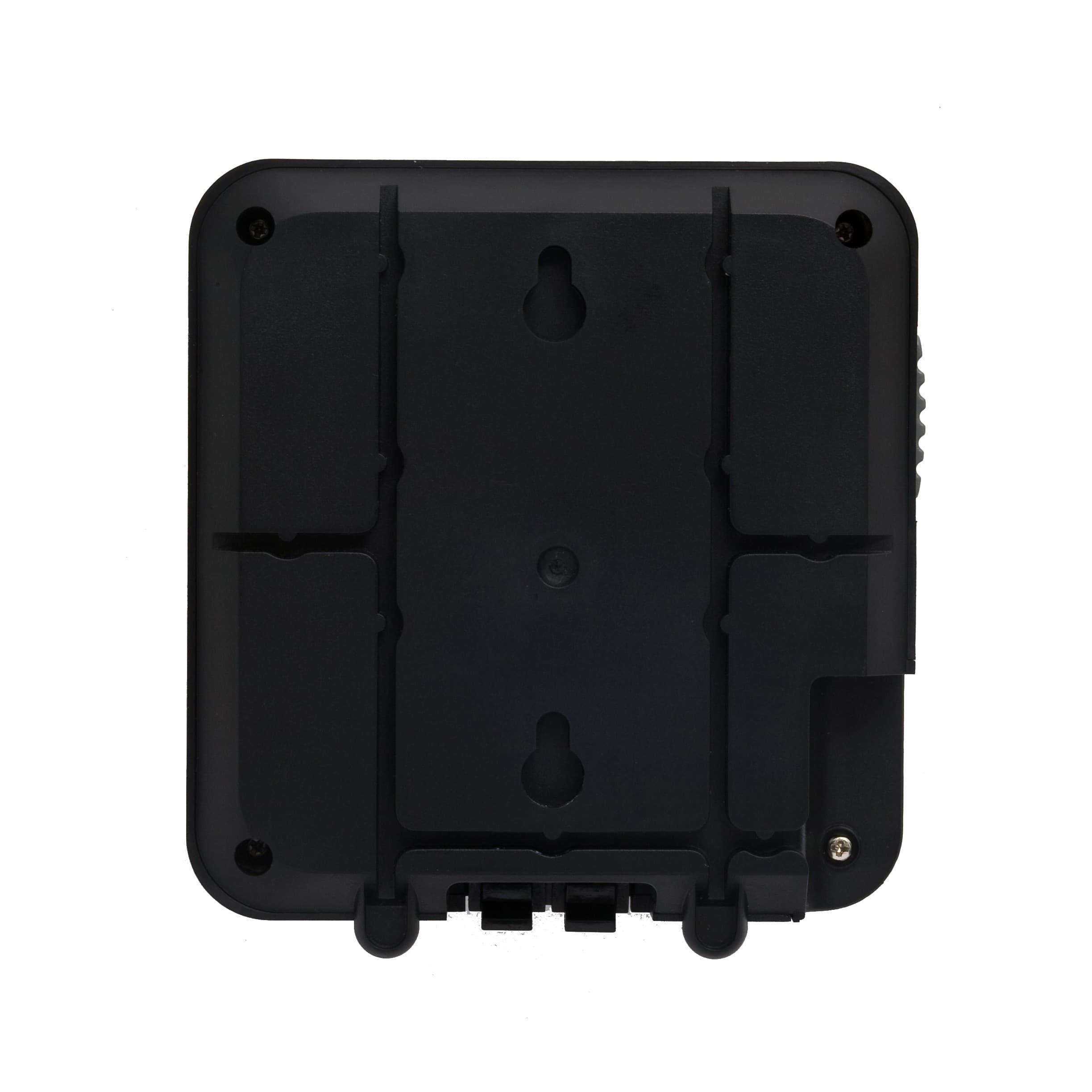
Click to zoom
Application Details
- Equipment Class
- DCD - Part 15 Low Power Transmitter Below 1705 kHz
- Date of Grant
- Jul 31, 2014
- Application Purpose
- Original Equipment
- Date of Application
- Jul 30, 2014
- Equipment Note
- Petfence Pet Containment System
- Frequency Range
- 0.01000000 - 0.01000000
- Country
- Ireland
Documents & Files
Document Text
Text extracted from the exhibit documents filed with the FCC. Open a document above to read the original.
Users Manual
This device complies with Part 15 of the FCC Rules. Operation is subject to the following two conditions: (1) This device may not cause harmful interference, and (2) This device must accept any interference received, including interference that may cause undesired operation. L'exploitation est autorisée aux deux conditions suivantes: (1) l'appareil ne doit pas produire de brouillage, et (2) l'utilisateur de l'appareil doit accepter tout brouillage radioélectrique subi, même si le brouillage est susceptible d'en compromettre le fonctionnement. WARNING: Changes or modifications not expressively approved by the party responsible for compliance could void the user's authority to operate the equipment.
Block Diagram
10kHz Oscillator Shock Pulse 0.1J / 8kV 10kHz Detector Amplitude Comparitor Audible Warning Pulse Charger Battery Charger 3 x NiMh cells DC INPUT 18VDC Wall Mounted Unit Collar Unit DRALL ERT ORS & OMISSIONS O BE REPO.RTE .DIMENSIONS WORK ONRLY FROALE FWING -THIS DRCT SDO NOM FIGURED A OM .B .A ScaleDa etwnrDa aDrefecwing eRreneRvision rD aitleTwing crtojeP riptionescDDateIssue rGenetesal No A Pet Fence PHNTO S ALECTO AFOR OMMENTC PJH BLOCK DIAGRAM FF 497 4MHz 4MHz (See Schematic)
Cover Letter(s)
Forcefield Active Technology Ltd. Bay 118 Shannon Free Zone Shannon Co. Clare Ireland Phone +353 (0)61 471511 Fax +353 (0)61 471685 Email sales(5)forcefield.ie Authority to Act as Agent May 21st 2014 American Certification Body, Inc. 6731 Whittier Avenue Suite C110 McLean, V A 22101 To Whom It May Concern: Compliance Engineering Ireland Ltd, is authorized to act on our behalf, until otherwise notified, for applications to American Certification Body, Inc. (ACB). We certify that we are not subject to denial of federal benefits, that includes FCC benefits, pursuant to Section 5301 of the Anti-Drug Abuse Act of 1988, 21 U.S.C. 862. Further, no party, as defined in 47 CFR 1.2002 (b)? to the application is subject to denial of federal benefits, that includes FCC benefits. Thank you, Agency Agreement Expiration Date: May 20th 2015 By: Title: <VU (Signature ) (Print name) On behalf of: Telephone: L1Y) (Company Name) Registered in Ireland No. 450323 VAT Reg. IE 9674314O WEEE Reg. IE 01107
External Photos
111 116 Front Elevation All dims in mm 116 38 111 All dims in mm. Side Profile Bottom View Forcefield Active Technology PET FENCEFCC FRN:0023609506 Rear View
ID Label/Location Info
Proposed new label incorporating FCC ID Forcefield Active Technology SERIAL NUMBER MODEL POWER:0.75W AVGINPUT: MADE IN CHINA FCC ID: 2ACD7PF02 18 VDCPULSE ENERGY:0.1J www.forcefield.ie
ID Label/Location Info
Label Position
Internal Photos
PCB Top PCB Bottom PCB Connectors
Operational Description
Pet Fence Theory of Operation / Product Description Description Pet Fence is a perimeter fencing system designed to constrain animals (primarily dogs) within a pre-set property boundary. The system consists of two main components – a) a transmission loop of wire laid along the perimeter and b), a detector worn by the dog. The transmission loop is fed from a wall mounted unit within the property. The transmission loop is a low voltage loop connected to the wall unit and powered via a wall mounted power supply rated 18VDC. The detector is located in the collar worn by the dog. This is powered by a 3.6V re-chargeable battery. Theory of Operation Transmitter The perimeter transmission loop acts as an induction loop radiating a very low-energy, short-range, electro-magnetic field at a frequency of 10kHz along its length. This field radiates uniformly about the conductor length and is detectable at approximately 3m. The unit circuitry is straightforward consisting of a 10kHz generator followed by an impedance-matching power amplifier delivering a low voltage waveform to the transmission loop. The wall unit also contains a battery charger which is used to re-charge the collar batteries from time to time. Both the wall mounted and collar units are microprocessor controlled. Receiver As the dog approaches the conductor the field is detected using a tuned receiver located in the collar unit. At lower field strengths an audible warning is sounded to alert the dog to the boundary proximity. Following an audible warning, and if the field strength increases, a small electric stimulus is delivered to the dog via two electrodes located in the collar. The applied electrical pulse is generated using the on-board microprocessor via a step-up transformer located in the collar unit. This stimulus is unpleasant and the dog very quickly learns to avoid triggering it. Following minimal training the animal will stop short of the boundary every time. Receiver Battery Charging The receiver battery is re-charged by removing it from the collar unit and placing it in the integral charger which is part of the wall mount transmitter unit. Charge times are approximately 6 hours. Wall Unit Power Supply The wall unit is powered from a separate power source which is rated 110-240VAC input with an 18VDC output at 300mA.
Schematics
TITLE SHANNO N I RELAND DWG NO. TEKELEK EURO PE LTD DATE DRA WN Issu e No. CH No. SHEET OF (C) TEKEL EK EURO PE 2012 04 M.Callanan 1 2 TD-5541 30- 8-2012 TEK 497 Pet Fence Transmitte r B1 Bat Unde r Charge IN OUT IC27805 IN OUT IC1LM338 Q3 1RLR/V3410 C1 1000uF 25V C21000uF 25V C6 100uF 10V C3 1000uF C40.1uF C70.1uF C50.1uF C90.1uF C1047nF D3 BZV55C 4v7 1 2 D4 BEEPE R LED 1 Green /Red LED 2 Po wer LED 3 Wire Vdd 1 RA5 2 RA4/AN3 3 MCLR/RA3 4 RC5 5 RC4 6 RC3/AN7 7 RC2/AN6 8 RC1/AN5 9 RC0/AN4 10 RA2/AN2 11 RA1/AN1 12 RA0/AN0 13 Vss 14 IC3 PI C16F676 R3470R R43K3 R83R0 R7 1K R610K R15 100R R9100KR11 33K R10 2K2 R12 12K R22K2 R5470R VR110K D1LL4148 D81N4148 R11K3 R14 470R R13 470R +12V +5V 1 2 J2 C80.1uF R16100R Vout R171K5 R1822K R191K D5 BZV55C 4v7 Vin D7Sc hottky SM D Vdd Vdd Vdd 1 2 3 4 5 J1 Vdd R20 10K Vdd MCLR PG D PG C MCLR R23 10K PG C Vdd +5V Vbatt R2110K R22 22K R24 470R +Vdd PG D C11 0.1uF +12V +12V Vbatt Batte ry voltage must be switched in as it will be higher thsn 5V dur ing charging process Batte ry Backup Feature J3 Vin SW 2 SW 1 D9BZV55C 5v6 R2633R R25 2K2 R292K2 PG D R27 10K R28 10K R30 10K R31 10K Q2 BC857B Q4 BC857B Q1 BC857B Q6BC847B Q7 BC847B Q5 BC857B D6Sc hottky SM D 6728 Unde r_I Unde r_I RL110K RL21K RL327K RL40R RL52K7 CL10.1uF DL1 ES1 BL RL610R Vdd 3 4 1 52 ICL1 TS931 Vdd Vdd 10kHz Oscillator
Test Setup Photos
Report Ref: 13E4771-1 Page 1 of 7 Project Number: 13E4771-1 FCC ID: 0023609506 Prepared for: Forcefield Active Technologies Ltd By Compliance Engineering Ireland Ltd Clonross Lane Derrockstown Dunshaughlin Co. Meath FCC Site Registration: 92592 Industry Canada Assigned Code: 8517A Date 25 th March 2013 FCC EQUIPMENT AUTHORISATION Test Report EUT Description Petfence Authorised: Compliance Engineering Ireland Ltd Raystown, Ratoath Road, Ashbourne, Co. Meath Tel: +353 1 8256722 Fax: +353 1 8256733 Report Ref: 13E4771-1 Page 2 of 7 List of Exhibits Title Page List of Exhibits Exhibit A – Technical Report Exhibit B – Photographs THIS REPORT SHALL NOT BE REPRODUCED EXCEPT IN FULL, WITHOUT THE WRITTEN APPROVAL OF COMPLIANCE ENGINEERING IRELAND LTD Report Ref: 13E4771-1 Page 3 of 7 Exhibit A – Technical Report Forcefield Active Technologies Ltd Applicant Name and Address The system covered under this authorisation report was designed, manufactured and assembled by Forcefield Active Technologies Ltd. The company's full name and mailing address is given below: Unit 118, Shannon Free Zone West, Shannon, Co. Clare Model Name The model number for the EUT covered under this application report is: Petfence Report Ref: 13E4771-1 Page 4 of 7 Test Setups FIGURE 1: Radiated Emissions Anechoic Chamber Test Setup – Test Distance 10m FIGURE 2: Radiated Emissions Outdoor Test Setup – Test Distance 10m Report Ref: 13E4771-1 Page 5 of 7 FIGURE 3: Conducted Emissions Test Setup Report Ref: 13E4771-1 Page 6 of 7 Exhibit B Test Configurations Figure 1: Radiated emissions setup 9 kHz to 30 MHz Figure 2: Radiated emissions setup 9 kHz to 30 MHz Report Ref: 13E4771-1 Page 7 of 7 Figure 3: Radiated emissions anechoic chamber 30 MHz to 1 GHz Figure 4: Conducted emissions setup
Contact Information
Applicant
Pat Frayne(General Manager)
Technical Contact
Test Firm
Compliance Engineering Ireland Ltd.John McAuley
Technical Specifications
| # | Rule Parts | Frequency Range | Power Output |
|---|---|---|---|
| 1 | 15C | 0.01 MHz - 0.01 MHz | - |