2ACD8S1500Bluetooth module
ENPING PASGAO ELECTRONICS CO., LTD.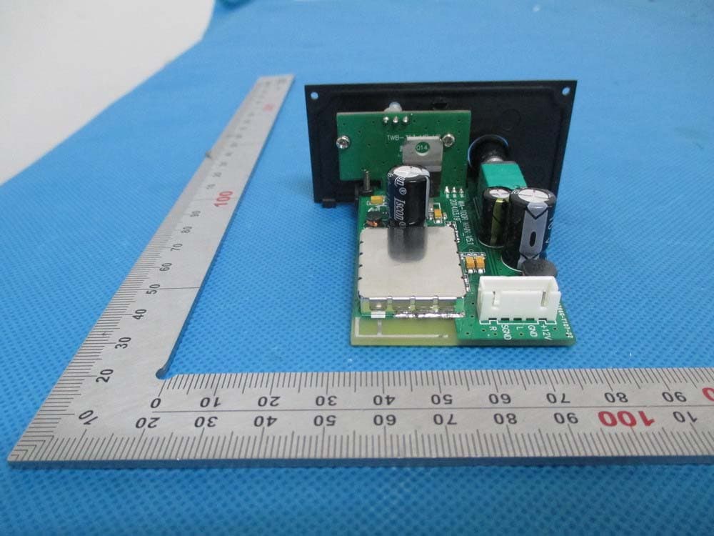
Click to zoom
Application Details
- Equipment Class
- DSS - Part 15 Spread Spectrum Transmitter
- Date of Grant
- Jun 03, 2014
- Application Purpose
- Original Equipment
- Date of Application
- Jun 03, 2014
- Equipment Note
- Bluetooth module
- Frequency Range
- 2402.00000000 - 2480.00000000
- Country
- China
Documents & Files
Document Text
Text extracted from the exhibit documents filed with the FCC. Open a document above to read the original.
Users Manual
Brand name:PASGAO FCC ID:2ACD8S1500 Faceplate Introduction ①power supply/volume button Turn the button to “off”, the bluetooth module is closed and power is off. Spin the button clockwise, bluetooth module will be on and volume will get high and higher. ②Status showing button Green light on, means the power supply of bluetooth module is on. Red light flickers quickly, means player (cell phone bluetooth) is not connected to the module. Red light flickers slowly (flicker about every 2 seconds) means it is playing. Red light off (only green light), means the playing is suspended or connection is finished & the module is ready to play. ③Press this button, it will play the former song. ④Press this button, it will change playing condition. When it is playing, it will suspend if pressing the button. When it doesn’t play, it will continue to play if pressing the button. ⑤Press this button, it will play next song. Notes:In order to avoid sonic boom when skipping or suspending playing, there will be a bit delay after pressing the button. The softwares of some mobile phones are not so suitable for the button controlling of bluetooth panel. Sometimes it even does not operate normally, which mainly cause d by software incompatibility. Pls try to install other playing software on your mobile phone. When the mobile phone is connected with bluetooth module for the first time, there may exist an occasion that the mobile phone can not search bluetooth device. The main reason for this occasion is that some mobile must search on-hook button first, and then it will be connected normally. To solve this probem, please press the playing button for a long time , and click “searching device” in setting functions of your mobile phone bluetooth, till bluetooth device is searched. The bluetooth will be connected when clicking bluetooth device. Module Instructions Firstly, turn o the power supply of bluetooth module. The green light on and red light flickers quickly means module is ready to be connected. Then open the bluetooth of your mobilephone (please make sure there is bluetooth module in your mobile phone, and it supports bluetooth headset ). Find bluetooth in the setting function of your mobile phone, and start bluetooth function. Then click “searching device ”in bluetooth setting. After the bluetooth find “AMPLIVOX S1500” ( this name can be produced according to customer’s requirements, and it should be settled during production. We will omit introducing this function in following passage), then click “AMPLIOX S1500”, then devices will be connected. When they are connected successfully, you can read “connected already” below “AMPLIOX S1500” on your phone. Or you can check if the status showing button is green. Thus devices finish pairing and being connected. when the bluetooth module is connected with bluetooth devices, you can start to play music on mobile phone. You can adjust the volume button to reach your requirements. Connectors sequence 0 Technical Data Bluetooth version: 3.0 Working Voltage: 8-12V Working current:60-80mA( not paired),45-65(paired) Standby current: 40-70mA(not paired) Output electrical level: -8.2 dBV)(390mVrms) Frequency response:20hz-18KHZ S/N:>68dB THD:0.05%(1kHZ) S1500Device name: "Attention ‐ Limited Modular Approval This RF Module is strictly limited to integration into battery powered host devices. Integration into devices that are directly or indirectly connected to AC lines must added via Class II Permissive Change." (OEM) Integrator has to assure compliance of the entire end‐product incl. the integrated RF Module. Additional measurements (15B) and/or equipment authorizations(e.g Verification) may need to be addressed depending on co‐location or simultaenous transmission issues if applicable. Integrator is reminded to assure that these installation instructions will not be made available to the end‐user of the final host device. With the documented max output power this RF Module meets the FCC SAR Exemption ‐ so it comply with any applicable RF exposure requirements in its final configuration. The RF Module is powered by battery,the antenna is PCB antenna and the antenna gain is 0 dBi The final host device, into which this RF Module is integrated" has to be labelledwith an auxilliary lable stating the FCC ID of the RF Module, such as"Contains FCC ID: 2ACD8S1500"." This device complies with part 15 of the FCC rules. Operation is subject to the following two conditions: (1) this device may not cause harmful interference, and (2) this device must accept any interference received, including interference that may cause undesired operation. "Changes or modifications to this unit not expressly approved by the party responsible for compliance could void the user’s authority to operate the equipment." This BT Module must be always marketed as it is mounted on this PCB with the dedicated onboard antenna. The BT module itself may not be integrated into any other application without C2P.
Cover Letter(s)
Applicant ENPING PASGAO ELECTRONICS CO., LTD. FCC ID: 2ACD8S1500 Section 15.212 Modular Transmitters Request for Modular Approval Request for Limited Modular Approval Y Requirements EUT Conditions Comply (Y/N) Single Modular Approval Requirements 1 The radio elements of the modular transmitter must have their own shielding. The physical crystal and tuning capacitors may be located external to the shielded radio elements. The metal shielding as shown on external photo, and the crystal and tuning capacitors are located in the shielded radio elements. Y 2 The modular transmitter must have buffered modulation/data inputs (if such inputs are provided) to ensure that the module will comply with Part 15 requirements under conditions of excessive data rates or over-modulation. Please refer the Schematic, The modular transmitter have buffered modulation/data inputs U1 Y 3 The modular transmitter must have its own power supply regulation. The modular has it’s own power supply regulation, refer to U1(OVC3960) with integrated LDO regulator Y 4 The modular transmitter must comply with the antenna and transmission system requirements of Sections 15.203, 15.204(b) and 15.204(c). The antenna must either be permanently attached or employ a “unique” antenna coupler (at all connections between the module and the antenna, including the cable). The “professional installation” provision of Section 15.203 is not applicable to modules but can apply to limited modular approvals under paragraph (b) of this section. Referring to onboard PCB antenna Y 5 The modular transmitter must be tested in a stand-alone configuration, i.e., the module must not be inside another device during testing for compliance with Part 15 requirements. Unless the transmitter module will be battery powered, it must comply with the AC line conducted requirements found in Section 15.207. AC or DC power lines and data input/output lines connected to the module must not contain ferrites, unless they will be marketed with the module (see Section 15.27(a)). The length of these lines shall be the length typical of actual use or, if that length is unknown, at least 10 centimeters to insure that there is no coupling between the case of the module and supporting equipment. Any accessories, peripherals, or support equipment connected to the module during testing shall be unmodified and commercially available equipment. Any accessories, peripherals, or support equipment connected to the module during testing shall be unmodified and commercially available (see Section 15.31(i)). Referring to the test setup photos. This module is tested on the test board in a stand-alone configuration.And AC Powerline Conducted Emissions not performed. Because this RF Module will be exclusively integrated into battery power host devices under strict control of the Grantee N 6 The modular transmitter must be equipped with either a permanently affixed label or must be capable of electronically displaying its FCC identification number. (A) If using a permanently affixed label, the modular transmitter must be labeled with its own FCC identification number, and, if the FCC identification number is not visible when the module is installed inside another device, then the outside of the device into which the module is installed must also display a label referring to the enclosed module. This exterior label can use wording such as the following: “Contains Transmitter Module FCC ID: XYZMODEL1” or “Contains FCC ID: XYZMODEL1.” Any similar wording that expresses the same meaning may be used. The Grantee may either provide such a label, an example of which must The modular was labeled with its own FCC ID. The outside of device in to which the module is installed will labeled ‘Contains TX FCC ID:2ACD8S1500, Please refer to User Manual Y be included in the application for equipment authorization, or, must provide adequate instructions along with the module which explain this requirement. In the latter case, a copy of these instructions must be included in the application for equipment authorization. (B) If the modular transmitter uses an electronic display of the FCC identification number, the information must be readily accessible and visible on the modular transmitter or on the device in which it is installed. If the module is installed inside another device, then the outside of the device into which the module is installed must display a label referring to the enclosed module. This exterior label can use wording such as the following: “Contains FCC certified transmitter module(s).” Any similar wording that expresses the same meaning may be used. The user manual must include instructions on how to access the electronic display. A copy of these instructions must be included in the application for equipment authorization. 7 The modular transmitter must comply with any specific rules or operating requirements that ordinarily apply to a complete transmitter and the manufacturer must provide adequate instructions along with the module to explain any such requirements. A copy of these instructions must be included in the application for equipment authorization. This RF Module will exclusively integrated into battery power host devices. The integration limitations are clearly addressed within the integration manual, please refer to the User Manual. Y 8 The modular transmitter must comply with any applicable RF exposure requirements in its final configuration. With the documented max output power this RF Module meets the FCC SAR Exemption,so it comply with any applicable RF exposure requirements in its final configuration. Y A limited modular approval may be granted for single or split modular transmitters that do not comply with all of the above requirements, e.g., shielding, minimum signaling amplitude, buffered modulation/data inputs, or power supply regulation, if the manufacturer can demonstrate by alternative means in the application for equipment authorization that the modular transm…
Text truncated - open the document above for the full version.
External Photos
External Photos TOP VIEW OF EUT BOTTOM VIEW OF EUT FRONT VIEW OF EUT BACK VIEW OF EUT LEFT VIEW OF EUT RIGHT VIEW OF EUT
ID Label/Location Info
FCC ID Label Location Model: S1500 Brand Name:PASGAO FCC ID: 2ACD8S1500 TWB‐313,WA‐100R AV AMPLIVOX, BES AUDIO
Internal Photos
Internal Photos OPEN VIEW OF EUT INTERNAL VIEW OF EUT-1 PCB ANT of EUT used PCB ANT of RF Moduleis not used. INTERNAL VIEW OF EUT-2 INTERNAL VIEW OF EUT-3
Test Report
Report No.: AGC01040140401FE03 Page 1 of 56 FCC Test Report Report No.: AGC01040140401FE03 FCC ID : 2ACD8S1500 APPLICATION PURPOSE : Original Equipment PRODUCT DESIGNATION : Bluetooth Module BRAND NAME : PASGAO, AV AMPLIVOX,BES AUDIO MODEL NAME : S1500, TWB‐313, WA‐100R CLIENT : ENPING PASGAO ELECTRONICS CO., LTD. DATE OF ISSUE : Apr.28, 2014 STANDARD(S) : FCC Part 15 Rules REPORT VERSION : V1.0 Attestation of Global Compliance (Shenzhen) Co., Ltd CAUTION: This report shall not be reproduced except in full without the written permission of the test laboratory and shall not be quoted out of context. Report No.: AGC01040140401FE03 Page 2 of 56 Report Revise Record Report Version Revise Time Issued Date Valid VersionNotes V1.0 / Apr.28, 2014 Valid Original Report Report No.: AGC01040140401FE03 Page 3 of 56 TABLE OF CONTENTS 1. VERIFICATION OF CONFORMITY ...................................................................................... 5 2. GENERAL INFORMATION .................................................................................................. 6 2.1. PRODUCT DESCRIPTION ........................................................................................................... 6 2.2. TABLE OF CARRIER FREQUENCYS .......................................................................................... 6 2.3. RECEIVER INPUT BANDWIDTH ................................................................................................. 7 2.4. EXAMPLE OF A HOPPING SEQUENCY IN DATA MODE ........................................................... 7 2.5. EQUALLY AVERAGE USE OF FREQUENCIES AND BEHAVIOUR ............................................ 7 2.6. RELATED SUBMITTAL(S) / GRANT (S) ....................................................................................... 8 2.7. TEST METHODOLOGY................................................................................................................ 8 2.8. SPECIAL ACCESSORIES ............................................................................................................ 8 2.9. EQUIPMENT MODIFICATIONS ................................................................................................... 8 3. MEASUREMENT UNCERTAINTY........................................................................................ 9 4. DESCRIPTION OF TEST MODES ........................................................................................ 9 5. SYSTEM TEST CONFIGURATION .................................................................................... 10 5.1. CONFIGURATION OF EUT SYSTEM ........................................................................................ 10 5.2. EQUIPMENT USED IN EUT SYSTEM ....................................................................................... 10 5.3. SUMMARY OF TEST RESULTS ................................................................................................ 10 6. TEST FACILITY .................................................................................................................. 11 7. PEAK OUTPUT POWER .................................................................................................... 12 7.1. MEASUREMENT PROCEDURE ................................................................................................ 12 7.2. TEST SET-UP (BLOCK DIAGRAM OF CONFIGURATION) ....................................................... 12 7.3. LIMITS AND MEASUREMENT RESULT .................................................................................... 13 8. 20DB BANDWIDTH ............................................................................................................ 19 8.1. MEASUREMENT PROCEDURE ................................................................................................ 19 8.2. TEST SET-UP (BLOCK DIAGRAM OF CONFIGURATION) ....................................................... 19 8.3. LIMITS AND MEASUREMENT RESULTS .................................................................................. 19 9. CONDUCTED SPURIOUS EMISSION ............................................................................... 26 9.1. MEASUREMENT PROCEDURE ................................................................................................ 26 9.2. TEST SET-UP (BLOCK DIAGRAM OF CONFIGURATION) ....................................................... 26 9.3. MEASUREMENT EQUIPMENT USED ....................................................................................... 26 9.4. LIMITS AND MEASUREMENT RESULT .................................................................................... 26 10. RADIATED EMISSION ..................................................................................................... 30 10.1. MEASUREMENT PROCEDURE .............................................................................................. 30 10.2. TEST SETUP ............................................................................................................................ 32 10.3. TEST RESULT .......................................................................................................................... 33 Report No.: AGC01040140401FE03 Page 4 of 56 11. BAND EDGE EMISSION .................................................................................................. 37 11.1. MEASUREMENT PROCEDURE .............................................................................................. 37 11.2. TEST SET-UP ........................................................................................................................... 37 11.3. TEST RESULT .......................................................................................................................... 38 12. NUMBER OF HOPPING FREQUENCY ............................................................................ 42 12.1. MEASUREMENT PROCEDURE .........................................................................................…
Text truncated - open the document above for the full version.
Test Setup Photos
APPENDIX IV PHOTOGRAPHS OF TEST SETUP FCC RADIATED EMISSION TEST SETUP Control box
Contact Information
Applicant
Xiaoxia Lu
Test Firm
Attestation of Global Compliance Shenzhen Co. Ltd.Forrest Lei
Technical Specifications
| # | Rule Parts | Frequency Range | Power Output |
|---|---|---|---|
| 1 | 15C | 2.40 GHz - 2.48 GHz | 5.30 mW |
Other Applications from ENPING PASGAO ELECTRONICS CO., LTD.
2ACD8BW16R
Nov 26, 2014Bodypack Receiver
Equipment Class
CXX - Communications Rcvr for use w/ licensed Tx and CBs
2ACD8PAH-800
May 14, 2014HANDHELD TRANSMITTER
Equipment Class
TNF - Licensed Non-Broadcast Transmitter Held to Face