2ACF6KTDC14M2M 2G/3G Data Terminal
KYB Trondule Co.,Ltd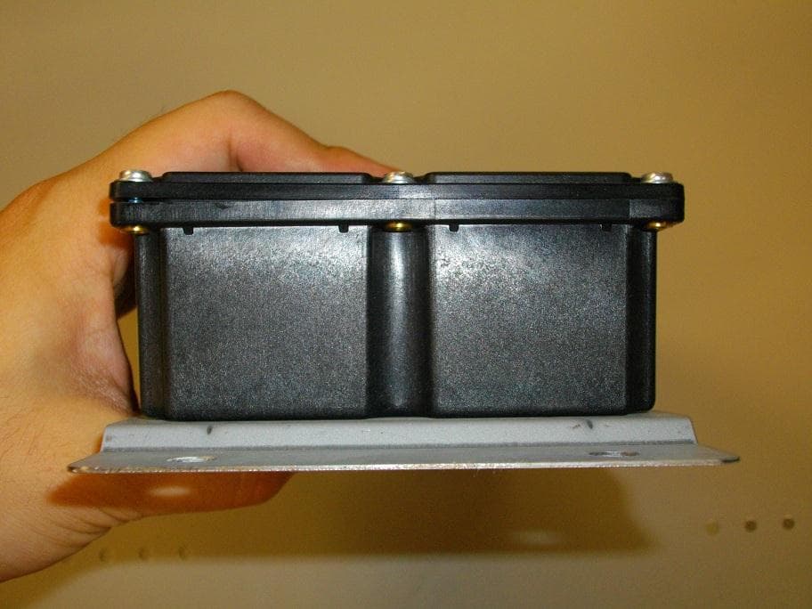
Click to zoom
Application Details
- Equipment Class
- PCB - PCS Licensed Transmitter
- Date of Grant
- Jul 14, 2014
- Application Purpose
- Original Equipment
- Date of Application
- Jul 14, 2014
- Equipment Note
- M2M 2G/3G Data Terminal
- Frequency Range
- 1852.40000000 - 1907.60000000
- Company
- KYB Trondule Co.,Ltd
- Country
- Japan
Documents & Files
Document Text
Text extracted from the exhibit documents filed with the FCC. Open a document above to read the original.
Users Manual
KTDC14 User manual 1. Product Information The product is a data transmission installed in the vehicle. It is designed to communicate with GSM/UMTS cellular network systems. In addition it has GNSS receiver and input/outputs interfaces that allow user applications, such as PC,etc. 2. Product description 2-1: General Specifications Model name : KTDC14 Input voltage : DC+8 to +32 V Current consumption : Standby: 36 mA : Transmission: 120 mA Operating temperature/humidity ranges : -20°C to 70°C 5 to 95% Storage temperature/humidity ranges : -30°C to 85°C 5 to 95% 2-2: External terminal Specifications GNSS antenna terminal: BNC-J (50 Ω) External interface: MX23A34NF1 (JAE) 3. Operational Description 1) Positioning by the GNSS 2) Data with the external interface (RS232C, General I/O, and CAN) 3) Transmission of the 1) and 2) through the GSM/UMTS cellular network systems. FCC Compliance Statements: This device complies with Part 15 of the FCC. Operation is subject to the following two conditions: (1) this device may not cause harmful interference, and (2) this device must accept any interference received, including interference that may cause undesired operation. Modifications not expressly approved by KYB Trondule Co.,Ltd. could void the user’s authority to operate the equipment. This equipment has been tested and found to comply with the limits for a Class B digital device, pursuant to Part 15 of the FCC Rules. These limits are designed to provide reasonable protection against harmful interference in a residential installation. This equipment generates, users and can radiate radio frequency energy and, if not installed and used in accordance with the instructions, may cause harmful interference to radio communications. However, there is no guarantee that interference will not occur in a particular installation. If this equipment does cause harmful interference to radio or television reception, which can be determined by turning the equipment off and on, the user is encouraged to try to correct the interference by one or more of the following measures: ‐ Reorient or relocate the receiving antenna. ‐ Increase the separation between the equipment and receiver. ‐ Connect the equipment into an outlet on a circuit different from that to which the receiver is connected. ‐ Consult the dealer or an experienced radio/TV technician for help. Radiofrequency radiation exposure Information: This equipment complies with FCC radiation exposure limits set forth for an uncontrolled environment. This equipment should be installed and operated with minimum distance of 20 cm between the radiator and your body. This transmitter must not be co-located or operating in conjunction with any other antenna or transmitter.
ID Label/Location Info
ApprovalLabel approvalModel LabelDomestic SIM ID Label 12 44 20 68 6.2 図 面 印 エ リ ア Label Layout 1:1A3 Model:KTDC14
Internal Photos
Cinterion Wireless Module PH8-P PH8-P Top side PH8-P Bottom Side
RF Exposure Info
Equipment Model Number: KTDC14 Acc. RSS-102 Issue 4 Chapter 2.5.2: Exemption from Routine Evaluation Limits – RF Exposure Evaluation RF exposure evaluation is required if the separation distance between the user and the device’s radiating element is greater than 20 cm, except when the device operates as follows: - below 1.5 GHz and the maximum e.i.r.p. of the device is equal to or less than 2.5 W; - at or above 1.5 GHz and the maximum e.i.r.p. of the device is equal to or less than 5 W. In these cases, the information contained in the RF exposure technical brief may be limited to information that demonstrates how the e.i.r.p. was derived. Prediction of MPE limit at given distance S = PG / 4π R 2 where: S = Power density P = Power input to the antenna (including tolerance of tune up procedure of +0.5 dB) G = Antenna gain R = Distance to the center of radiation of the antenna The table below is excerpted from Table 1B of 47 CFR 1.1310 titled “Limits for Maximum Permissible Exposure (MPE), Limits for General Population/Uncontrolled Exposure” Frequency Range (MHz) Power Density (mW/cm 2 ) Averaging Time (minutes) 300 -1500 f/1500 30 1500 - 100000 1.0 30 where f = Frequency (MHz) Prediction: GSM 850 P Max power input to the antenna: not measured G Antenna gain: not measured P*G ERP 32.4 dBm / 1737.8 mW R Distance: 20 cm S MPE limit for uncontrolled exposure: 0.56 mW/cm 2 Calculated Power density: 0.35 mW/cm 2 This prediction demonstrates the following: The power density levels at a distance of 20 cm are below the maximum levels allowed by FCC regulations. The radiated power is below the maximum level allowed by IC regulations. Prediction: GSM 1900 P Max power input to the antenna: not measured G Antenna gain: not measured P*G EIRP 32.0 dBm / 1584.9 mW R Distance: 20 cm S MPE limit for uncontrolled exposure: 1 mW/cm 2 Calculated Power density: 0.32 mW/cm 2 This prediction demonstrates the following: The power density levels at a distance of 20 cm are below the maximum levels allowed by FCC regulations The radiated power is below the maximum level allowed by IC regulations. Prediction: WCDMA 850 P Max power input to the antenna: not measured G Antenna gain: not measured P*G ERP 24.1 dBm / 257.0 mW R Distance: 20 cm S MPE limit for uncontrolled exposure: 0.56 mW/cm 2 Calculated Power density: 0.05 mW/cm 2 This prediction demonstrates the following: The power density levels at a distance of 20 cm are below the maximum levels allowed by FCC regulations The radiated power is below the maximum level allowed by IC regulations. Prediction: WCDMA 1900 P Max power input to the antenna: not measured G Antenna gain: not measured P*G EIRP 26.1 dBm / 407.4 mW R Distance: 20 cm S MPE limit for uncontrolled exposure: 1 mW/cm 2 Calculated Power density: 0.08 mW/cm 2 This prediction demonstrates the following: The power density levels at a distance of 20 cm are below the maximum levels allowed by FCC regulations The radiated power is below the maximum level allowed by IC regulations. Signature: Date: 2014-06-26 NAME (Please print or type): Dipl.-Ing. (FH) Stefan Bös TITLE (Please print or type): Senior Testing Manager COMPANY (Please print or type): Cetecom ICT Services GmbH
Test Report
Final Report on Cinterion Wireless Module PH8-P HW: Release 2, B2 SW: Revision 01.370 MDE_CINTE_1107_FCCb acc. Title 47 CFR chapter I part 22 subpart H Report Reference: Se ptember 22, 2011Date: Test Laboratory: 7Layers AG Borsigstr. 11 40880 Ratingen Germany Note: The following test results relate only to the devices specified in this document. This report shall not be reproduced in parts without the written approval of the test laboratory. 7Layers AG Aufsichtsratsvorsitzender Registergericht registered in: Borsigstrasse 11 Chairman of the Supervisory Board: Düsseldorf, HRB 44096 40880 Ratingen, Germany Markus Becker USt-IdNr VAT No.: Phone: +49 (0) 2102 749 0 Vorstand Board: DE 203159652 Fax: +49 (0) 2102 749 350 Dr. H.-J. Meckelburg TAX No. 147/5869/0385 www.7Layers.com Reference: MDE_CINTE_1107_FCCb acc. Title 47 CFR chapter I part 22 subpart H 2.2Detailed Description of OUT Samples Sample : b01 OUT IdentifierPH8-P Sample Descriptionsample #02 Serial No.IMEI: 004401080640028 HW StatusRelease 2, B2 SW StatusRevision 01.370 Date of Receipt2011/08/05 Low VoltageLow Temp.3.3 V-10 °C High Temp.High Voltage4.2 V+55 °C Normal Temp.Nominal Voltage4.2 V+22 °C 2.3OUT Features Features for OUT: PH8-P Allowed ValuesDesignationDescriptionSupported Value(s) Features for scope: FCC_v2 ACThe OUT is powered by or connected to AC Mains DCThe OUT is powered by or connected to DC Mains EDGE850EUT supports EDGE in the band 824 MHz - 849 MHz EDGE1900 EUT supports EDGE in the band 1850 MHz - 1910 MHz FDD2EUT supports UMTS FDD2 in the band 1850 MHz - 1910 MHz FDD5EUT supports UMTS FDD5 in the band 824 MHz - 849 MHz GSM850EUT supports GSM850 band 824MHz - 849MHz HSDPA- FDD2 EUT supports UMTS FDD2 HSDPA in the band 1850 MHz - 1910 MHz HSDPA- FDD5 EUT supports UMTS FDD5 HSDPA in the band 824 MHz - 849 MHz HSUPA- FDD2 EUT supports UMTS FDD2 HSUPA in the band 1850 MHz - 1910 MHz HSUPA- FDD5 EUT supports UMTS FDD5 HSUPA in the band 824 MHz - 849 MHz PantCpermanent fixed antenna connector, which may be built-in, designed as an indispensable part of the equipment PCS1900EUT supports PCS1900 band 1850MHz - 1910MHz Page 4 of 210 Reference: MDE_CINTE_1107_FCCb acc. Title 47 CFR chapter I part 22 subpart H 2.4Auxiliary Equipment AE No.Serial No.SW StatusHW StatusDescriptionType Designation AE 09----Direct RF coupler to SMA AE 02----Flex cable AE Ant1----GSM/UMTS antenna AE Ant2----UMTS antenna AE Ant3ANN-MS-0-005 M827B 601657--GPS antenna AE 01DSB75_B1.1_0152---Evaluation board 2.5Setups used for Testing For each setup a relation is given to determine if and which samples and auxiliary equipment is used. The left side list all OUT samples and the right side lists all auxiliary equipment for the given setup. Sample No.Sample DescriptionAE No.AE Description Setup No.List of OUT samplesList of auxiliary equipment B01_direct (used for measurement using antenna port at the module) AE 09Direct RF coupler to SMAb01sample #02Sample: AE 02Flex cable AE 01Evaluation board B01_rad (used for radiated measurement using external antennas) AE 02Flex cableb01sample #02Sample: AE Ant1GSM/UMTS antenna AE Ant2UMTS antenna AE Ant3GPS antenna AE 01Evaluation board B01_RF1 (used for measurement at external RF connector RF1) AE 02Flex cableb01sample #02Sample: AE 01Evaluation board Page 5 of 210 Reference: MDE_CINTE_1107_FCCb acc. Title 47 CFR chapter I part 22 subpart H 3Results 3.1General Available at the test laboratory. The results of the inspection are described on the following pages, where 'Conformity' or 'Passed' means that the certification criteria were verified and that the tested device is conform to the applied standard. In cases where 'Declaration' is printed, the required documents are available in the manufacturers product documentation. In cases where 'not applicable' is printed, the test case requirements are not relevant to the specific equipment implementation. Documentation of tested devices: Interpretation of the test results: 3.2List of the Applicable Body (Body for Scope: FCC_v2) DesignationDescription Part 22, Subpart H - Cellular Radiotelephone ServiceFCC47CFRChIPART22PUBLIC MOBILE SERVICES 3.3List of Test Specification Test Specification:FCC part 2 and 22 Version10-1-10 Edition Title:PART 2 - GENERAL RULES AND REGULATIONS PART 22 - PUBLIC MOBILE SERVICES Page 6 of 210 Reference: MDE_CINTE_1107_FCCb acc. Title 47 CFR chapter I part 22 subpart H 3.4Summary Test Case Identifier / Name SetupDate of TestResultTest (condition)Ref. Lab 22.1 RF Power Output §2.1046, §22.913 22.1; Frequency Band = 850, Mode = EDGE, Channel = 128, Frequency = 824.2MHz, Method = conducted 2011/08/19B01_directLab 2Passed 22.1; Frequency Band = 850, Mode = EDGE, Channel = 190, Frequency = 836.6MHz, Method = conducted 2011/08/19B01_directLab 2Passed 22.1; Frequency Band = 850, Mode = EDGE, Channel = 251, Frequency = 848.8MHz, Method = conducted 2011/08/19B01_directLab 2Passed 22.1; Frequency Band = 850, Mode = GSM, Channel = 128, Frequency = 824.2MHz, Method = conducted 2011/08/19B01_directLab 2Passed 22.1; Frequency Band = 850, Mode = GSM, Channel = 190, Frequency = 836.6MHz, Method = conducted 2011/08/19B01_directLab 2Passed 22.1; Frequency Band = 850, Mode = GSM, Channel = 251, Frequency = 848.8MHz, Method = conducted 2011/08/19B01_directLab 2Passed 22.1; Frequency Band = FDD5, Mode = HSDPA_subtest_1, Channel = 4132, Frequency = 826.4MHz, Method = conducted 2011/08/19B01_directLab 2Passed 22.1; Frequency Band = FDD5, Mode = HSDPA_subtest_1, Channel = 4183, Frequency = 836.6MHz, Method = conducted 2011/08/19B01_directLab 2Passed 22.1; Frequency Band = FDD5, Mode = HSDPA_subtest_1, Channel = 4233, Frequency = 846.6MHz, Method = conducted 2011/08/19B01_directLab 2Passed 22.1; Frequency Band = FDD5, Mode = HSDPA_subtest_2, Channel = 4132, Frequency = 826.4MHz, Method = conducted 2011/08/19B01_directLab 2Passed 22.1; Frequency Band = FDD5, Mode = HSDPA_subtest_2, Channel = 4183, Frequency = 836.6MHz, Method = conducted 2011/08/19B01_directLab 2Pas…
Text truncated - open the document above for the full version.
Test Report
Final Report on Cinterion Wireless Module PH8-P HW: Release 2, B2 SW: Revision 01.370 MDE_CINTE_1107_FCCc acc. Title 47 CFR chapter I part 24 subpart E Report Reference: Se ptember 22, 2011Date: Test Laboratory: 7Layers AG Borsigstr. 11 40880 Ratingen Germany Note: The following test results relate only to the devices specified in this document. This report shall not be reproduced in parts without the written approval of the test laboratory. 7Layers AG Aufsichtsratsvorsitzender Registergericht registered in: Borsigstrasse 11 Chairman of the Supervisory Board: Düsseldorf, HRB 44096 40880 Ratingen, Germany Markus Becker USt-IdNr VAT No.: Phone: +49 (0) 2102 749 0 Vorstand Board: DE 203159652 Fax: +49 (0) 2102 749 350 Dr. H.-J. Meckelburg TAX No. 147/5869/0385 www.7Layers.com Reference: MDE_CINTE_1107_FCCc acc. Title 47 CFR chapter I part 24 subpart E 2.2Detailed Description of OUT Samples Sample : b01 OUT IdentifierPH8-P Sample Descriptionsample #02 Serial No.IMEI: 004401080640028 HW StatusRelease 2, B2 SW StatusRevision 01.370 Date of Receipt2011/08/05 Low VoltageLow Temp.3.3 V-10 °C High Temp.High Voltage4.2 V+55 °C Normal Temp.Nominal Voltage4.2 V+22 °C 2.3OUT Features Features for OUT: PH8-P Allowed ValuesDesignationDescriptionSupported Value(s) Features for scope: FCC_v2 ACThe OUT is powered by or connected to AC Mains DCThe OUT is powered by or connected to DC Mains EDGE850EUT supports EDGE in the band 824 MHz - 849 MHz EDGE1900 EUT supports EDGE in the band 1850 MHz - 1910 MHz FDD2EUT supports UMTS FDD2 in the band 1850 MHz - 1910 MHz FDD5EUT supports UMTS FDD5 in the band 824 MHz - 849 MHz GSM850EUT supports GSM850 band 824MHz - 849MHz HSDPA- FDD2 EUT supports UMTS FDD2 HSDPA in the band 1850 MHz - 1910 MHz HSDPA- FDD5 EUT supports UMTS FDD5 HSDPA in the band 824 MHz - 849 MHz HSUPA- FDD2 EUT supports UMTS FDD2 HSUPA in the band 1850 MHz - 1910 MHz HSUPA- FDD5 EUT supports UMTS FDD5 HSUPA in the band 824 MHz - 849 MHz PantCpermanent fixed antenna connector, which may be built-in, designed as an indispensable part of the equipment PCS1900EUT supports PCS1900 band 1850MHz - 1910MHz Page 4 of 213 Reference: MDE_CINTE_1107_FCCc acc. Title 47 CFR chapter I part 24 subpart E 2.4Auxiliary Equipment AE No.Serial No.SW StatusHW StatusDescriptionType Designation AE 09----Direct RF coupler to SMA AE 02----Flex cable AE Ant1----GSM/UMTS antenna AE Ant2----UMTS antenna AE Ant3ANN-MS-0-005 M827B 601657--GPS antenna AE 01DSB75_B1.1_0152---Evaluation board 2.5Setups used for Testing For each setup a relation is given to determine if and which samples and auxiliary equipment is used. The left side list all OUT samples and the right side lists all auxiliary equipment for the given setup. Sample No.Sample DescriptionAE No.AE Description Setup No.List of OUT samplesList of auxiliary equipment B01_direct (used for measurement using antenna port at the module) AE 09Direct RF coupler to SMAb01sample #02Sample: AE 02Flex cable AE 01Evaluation board B01_rad (used for radiated measurement using external antennas) AE 02Flex cableb01sample #02Sample: AE Ant1GSM/UMTS antenna AE Ant2UMTS antenna AE Ant3GPS antenna AE 01Evaluation board B01_RF1 (used for measurement at external RF connector RF1) AE 02Flex cableb01sample #02Sample: AE 01Evaluation board Page 5 of 213 Reference: MDE_CINTE_1107_FCCc acc. Title 47 CFR chapter I part 24 subpart E 3Results 3.1General Available at the test laboratory. The results of the inspection are described on the following pages, where 'Conformity' or 'Passed' means that the certification criteria were verified and that the tested device is conform to the applied standard. In cases where 'Declaration' is printed, the required documents are available in the manufacturers product documentation. In cases where 'not applicable' is printed, the test case requirements are not relevant to the specific equipment implementation. Documentation of tested devices: Interpretation of the test results: 3.2List of the Applicable Body (Body for Scope: FCC_v2) DesignationDescription Part 24, Subpart E - Broadband PCSFCC47CFRChIPART24PERSONAL COMMUNICATIONS SERVICES 3.3List of Test Specification Test Specification:FCC part 2 and 24 Version10-1-10 Edition Title:PART 2 - GENERAL RULES AND REGULATIONS PART 24 - PERSONAL COMMUNICATIONS SERVICES Page 6 of 213 Reference: MDE_CINTE_1107_FCCc acc. Title 47 CFR chapter I part 24 subpart E 3.4Summary Test Case Identifier / Name SetupDate of TestResultTest (condition)Ref. Lab 24.1 RF Power Output §2.1046, §24.232 24.1; Frequency Band = 1900, Mode = EDGE, Channel = 512, Frequency = 1850.2MHz, Method = conducted 2011/08/19B01_directLab 2Passed 24.1; Frequency Band = 1900, Mode = EDGE, Channel = 661, Frequency = 1880.0MHz, Method = conducted 2011/08/19B01_directLab 2Passed 24.1; Frequency Band = 1900, Mode = EDGE, Channel = 810, Frequency = 1909.8MHz, Method = conducted 2011/08/20B01_directLab 2Passed 24.1; Frequency Band = 1900, Mode = GSM, Channel = 512, Frequency = 1850.2MHz, Method = conducted 2011/08/19B01_directLab 2Passed 24.1; Frequency Band = 1900, Mode = GSM, Channel = 661, Frequency = 1880.0MHz, Method = conducted 2011/08/19B01_directLab 2Passed 24.1; Frequency Band = 1900, Mode = GSM, Channel = 810, Frequency = 1909.8MHz, Method = conducted 2011/08/19B01_directLab 2Passed 24.1; Frequency Band = FDD2, Mode = HSDPA_subtest_1, Channel = 9262, Frequency = 1852.4MHz, Method = conducted 2011/08/20B01_directLab 2Passed 24.1; Frequency Band = FDD2, Mode = HSDPA_subtest_1, Channel = 9400, Frequency = 1880MHz, Method = conducted 2011/08/20B01_directLab 2Passed 24.1; Frequency Band = FDD2, Mode = HSDPA_subtest_1, Channel = 9538, Frequency = 1907.6MHz, Method = conducted 2011/08/20B01_directLab 2Passed 24.1; Frequency Band = FDD2, Mode = HSDPA_subtest_2, Channel = 9262, Frequency = 1852.4MHz, Method = conducted 2011/08/20B01_directLab 2Passed 24.1; Frequency Band = FDD2, Mode = HSDPA_subtest_2, Channel = 9400, Frequency = 1880MHz, Method = conducted 2011/08/20B01…
Text truncated - open the document above for the full version.
Test Report
2014-06-20 Page 1 of 47 TEST REPORT Test report no.: 1-5825/13-33-07 Testing laboratory Applicant CETECOM ICT Services GmbH Untertuerkheimer Strasse 6 – 10 66117 Saarbruecken / Germany Phone: + 49 681 5 98 - 0 Fax: + 49 681 5 98 - 9075 Internet: http://www.cetecom.com e-mail: [email protected] Accredited Testing Laboratory: The testing laboratory (area of testing) is accredited according to DIN EN ISO/IEC 17025 (2005) by the Deutsche Akkreditierungsstelle GmbH (DAkkS) The accreditation is valid for the scope of testing procedures as stated in the accreditation certificate with the registration number: D-PL-12076-01-01 Area of Testing: Radio Communications & EMC (RCE) KYB Trondule Co.,Ltd 3909, Ura, Nagaoka Niigata 949-5406 / JAPAN Phone: -/- Fax: + 81 258 92 6921 Contact: Katsuyuki Harada e-mail: [email protected] Phone: +81 258 92 6903 Manufacturer KYB Trondule Co.,Ltd 3909, Ura, Nagaoka Niigata 949-5406 / JAPAN Test standard/s 47 CFR Part 22 Title 47 of the Code of Federal Regulations; Chapter I; Part 22 - Public mobile services 47 CFR Part 24 Title 47 of the Code of Federal Regulations; Chapter I; Part 24 - Personal communications services For further applied test standards please refer to section 3 of this test report. Test Item Kind of test item: 3G data terminal with integrated module Model name: KTDC14 FCC ID: 2ACF6KTDC14 IC: -/- Frequency: GSM: 824.2 – 848.8 MHz, 1850.2 – 1909.8 MHz UMTS: 826.4 – 848.6 MHz, 1852.4 – 1907.6 MHz Technology tested: GSM, UMTS Antenna: Integrated antenna Power supply: 24.0V DC by external power supply Temperature range: -20°C to +55°C This test report is electronically signed and valid without handwriting signature. For verification of the electronic signatures, the public keys can be requested at the testing laboratory. Test report authorised: Test performed: Stefan Bös Tobias Wittenmeier Senior Testing Manager Expert Test report no.: 1-5825/13-33-07 2014-06-20 Page 2 of 47 1 Table of contents 1 Table of contents ............................................................................................................................................ 2 2 General information ....................................................................................................................................... 4 2.1 Notes and disclaimer .......................................................................................................................... 4 2.2 Application details ............................................................................................................................... 4 3 Test standard/s ............................................................................................................................................... 4 4 Test environment ............................................................................................................................................ 5 5 Test item .......................................................................................................................................................... 5 5.1 Additional information ........................................................................................................................ 5 6 Test laboratories sub-contracted ................................................................................................................. 5 7 Description of the test setup ......................................................................................................................... 6 7.1 Radiated measurements chamber C ................................................................................................. 6 7.2 Radiated measurements 12.75 GHz to 25 GHz ................................................................................. 7 7.3 Radiated measurements 12.75 GHz to 50 GHz ................................................................................. 8 8 Summary of measurement results ............................................................................................................... 9 8.1 GSM 850 ................................................................................................................................................ 9 8.2 PCS 1900 .............................................................................................................................................. 9 8.3 UMTS band II ...................................................................................................................................... 10 8.4 UMTS band V...................................................................................................................................... 10 9 RF measurements ........................................................................................................................................ 11 9.1 Results GSM 850 ............................................................................................................................... 11 9.1.1 RF output power ....................................................................................................................... 11 9.1.2 Frequency stability .................................................................................................................... 13 9.1.3 Spurious emissions radiated .................................................................................................... 14 9.1.4 Spurious emissions conducted ................................................................................................. 18 9.1.5 Block edge compliance ............................................................................................................. 18 9.1.6 Occupied bandwidth ................................................................................................................. 18 9.2 Results PCS 1900 ............................................................................................................…
Text truncated - open the document above for the full version.
Contact Information
Applicant
Katsuyuki Harada
Test Firm
cetecom advanced GmbHGerald Schmidt
Technical Specifications
| # | Rule Parts | Frequency Range | Power Output | Emission | Tolerance |
|---|---|---|---|---|---|
| 6 | 24E | 1.85 GHz - 1.91 GHz | 410.00 mW | 4M15F9D | 38 Hz |