FCCID.CO- FCC ID Database
HomeCompaniesEquipment ClassesSearch

© 2026 FCC ID Database. All rights reserved.

AboutContactData sourced from FCC public records
  1. Home/
  2. ez-Wheel SAS/
  3. 2ACF9EZRTHW1

2ACF9EZRTHW1Remote using a zigbee module

ez-Wheel SAS
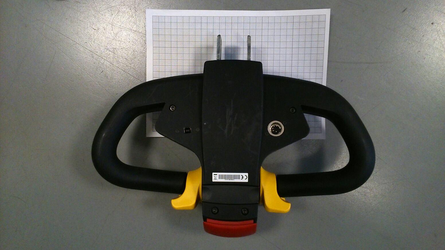
Remote using a zigbee module - FCC ID 2ACF9EZRTHW1 - ez-Wheel SAS
Click to zoom

Application Details

Equipment Class
DTS - Digital Transmission System
Date of Grant
Jul 01, 2014
Application Purpose
Original Equipment
Date of Application
Jul 01, 2014
Equipment Note
Remote using a zigbee module
Frequency Range
2405.00000000 - 2475.00000000
Company
ez-Wheel SAS
Country
France

Documents & Files

Select a file to view

Users Manual

↗

Cover Letter(s)

↗
↗

External Photos

↗

ID Label/Location Info

↗
↗

Internal Photos

↗

Test Report

↗

Test Setup Photos

↗

Document Text

Text extracted from the exhibit documents filed with the FCC. Open a document above to read the original.

Users Manual

Operating Manual autonomous wheels ezW10 and ezW300 tiller head ezRTH wireless versions Revision B – May 2014 Index 1. Characteristics of the ez-Wheel product 4 2. Installation of the ez-Wheel product 5 □ Positioning/direction of operation 5 □ Mounting of the tiller head 5 □ Mounting of the wheel on the application 5 3. Use of the ez-Wheel product 7 □ Starting up for the first time 7 □ Use 7 □ Charging the wheel 8 □ Charging of the tiller head batteries 9 □ Versions with tyres: Changing a tyre 9 □ Versions with solid tyres 10 4. Precautions for use 10 □ Wheel maintenance 10 □ Prolonged shutdown 11 □ Precautions for use relative to the wheel 11 □ Precautions for use relative to the tiller head 11 □ Safety rules in relation to the batteries 11 □ Incorrect use 11 5. Customer Department contact 11 6. Troubleshooting 12 □ Display 12 □ Changing a tyre 12 □ Wheel malfunctioning 12 □ Tiller head malfunction 13 □ System reset procedure 13 7. Product end-of-life 13 8. Compliance with the limits for digital device 13 9. Radiation exposure limits 14 □ The wheel 14 □ The tiller head 14 Display 15 Declaration of incorporation 16 Declaration of CE conformity 16 Do not use ez-Wheel products for other purposes or in other conditions than those mentioned in the technical documentation. Read and make sure you have understood the manual before using ez-Wheel products. Observe all the warnings and usage instructions in this manual. Keep this manual for reference throughout the life of the product. In the event of loss, you can obtain a copy of this manual from the ez-Wheel Customer Department If the product is transferred to another owner, make sure that the manual is transferred as well. The characteristics, descriptions, and illustrations in this document are applicable at the date of publication. ez-Wheel reserves the right to make any modifications and revisions to this document. Product users obtain their own information on these modifications. Page 4 User's Manual – Revision B – May 2014 1. Characteristics of the ez-Wheel product The range of autonomous wheels, ezW10 and ezW300, enables powerful electric drive to be installed quickly and easily. ezW10 and ezW300 wheels are controlled by the interface in the tiller head ezRTH via a wireless communication system. This operating manual contains the instructions to be followed for installation, use and maintenance of ezW10 and ezW300 wheels and the ezRTH tiller head Page 5 User's Manual – Revision B – May 2014 2. Installation of the ez-Wheel product All mechanical drawings that could serve for the installation of ez-Wheel products are available on request. All the accessories mentioned are available in the ez-Wheel catalogue. The wheels and the tiller heads are designed to work together according to the configuration described in the configuration sheet delivered with the equipment. □ Positioning/direction of operation • Refer to the configuration sheet. • Take the tiller head with the serial number mentioned on the configuration sheet. • Identify the serial numbers of the wheels given on the configuration sheet. • Prepare and position the corresponding wheels, as shown on the configuration sheet □ Mounting of the tiller head • The tiller head must be held by the plate situated on the back of the box. • Fix the tiller head to the application in such a way as to ensure that it is intuitive and ergonomic for the user to handle it. All mechanical drawings that could serve for the installation of the tiller head are available on request. □ Mounting of the wheel on the application • Check that the tiller head is switched off: All lights are off. • Inspect the general condition of the wheel and check for damage. • Check the condition of the wheel: Press the ON/OFF zone on the wheel label and check that the light is green. Page 6 User's Manual – Revision B – May 2014 • Check that the application on which the wheel is going to be mounted has a spindle with a diameter of 16 mm, of which the length corresponds to the thickness of the wheel, for each wheel. • Check the presence of a hexagon anti-rotation zone (XC 18 steel or equivalent hardness). • Position the wheel on the spindle and make sure that the hexagon zone of the wheel is correctly inserted in that of the application. • The optional ezMAR anti-rotation washer accessory can be used. Remove the M3 screw from the ezMAR washer with a 2.5 mm Allen key. - Position the hexagon zone of the ezMAR clamp on the wheel spindle. It is possible to use a mallet for this operation but the wheel spindle must not be damaged in any circumstances. Face A of the clamp should be against the wheel. - Tighten the M3 side screw with an Allen key to ensure that the clamp is locked around the hexagon zone. CHC M3x12 SCREW 2.5 mm Allen key Mallet • Lock the wheel to the spindle with a screw on the side opposite the hexagon zone (or both sides of the spindle if the application is fitted with a fork or a yoke) • Check the holding of the wheel before putting the tiller head into operation. • Repeat this operation for each wheel if the system has several wheels. Face A Face B Page 7 User's Manual – Revision B – May 2014 3. Use of the ez-Wheel product □ Starting up for the first time • Check the condition of the wheel: Press the ON/OFF zone on the wheel label and check that the light is green. (The light indicates the level of charge of the battery. See "Display" appendix) • If the application has several wheels, repeat the operation for all the wheels. • Press the ON/OFF button on the tiller head and check that the light is green. • Check that communication is established between the tiller head and the wheels: The light lights up green on the tiller head. It is preferable to recharge the wheels completely before using for the first time. (See: Charging the wheel) It is essential to charge the tiller head before using it for the first time. If one of these steps does not take place as described, refer to "troubleshooting" or contact the e…

Text truncated - open the document above for the full version.

Internal Photos

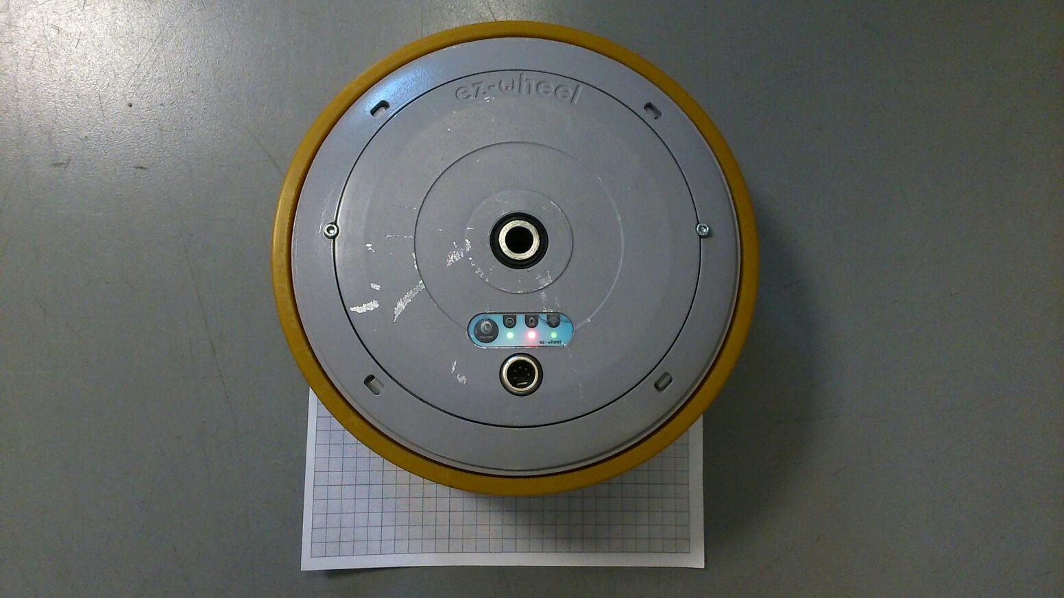
22/05/14 This document is confidential and may not be reproduced without ez-Wheel authorization. PCB – ezRTH Carte interface E_200186 22/05/14 This document is confidential and may not be reproduced without ez-Wheel authorization. Zoom zone RF carte E_200186 22/05/14 This document is confidential and may not be reproduced without ez-Wheel authorization. Carte IHM E_200731 22/05/14 This document is confidential and may not be reproduced without ez-Wheel authorization. Connexion carte interface + carte IHM

Test Report

Siège Social : Emitech - 3, rue des Coudriers - Z.A. de l’Observatoire - 78180 MONTIGNY LE BX - France Siret : 344 545 645 00022 - Tél. : 33 (0)1 30 57 55 55 - Fax : 33 (0)1 30 43 74 48 - E-mail : [email protected] - URL : www.emitech.fr S.A. au capital de 1 560 000 € - R.C.S. VERSAILLES 344 545 645 - APE 7112B RR051-14-101064-2-A Ed. 0 RADIO test report According to the standard: CFR47 FCC PART 15 Equipment under test: Wireless Tiller Head Model: ezRTH FCCID: 2ACF9EZRTHW1 Company: EZ WHEEL DISTRIBUTION: Mrs Marie (Company: EZ WHEEL ) Number of pages: 39 with 6 appendixes Technical Verification and Ed. Date Modified Written by Quality Approval pages Name Visa Name Visa 0 1-July-2014 Creation M. DUMESNIL O. ROY Duplication of this test report is only permitted for an integral photographic facsimile. It includes the number of pages referenced here above. This document is the result of testing a specimen or a sample of the product submitted. It does not imply an assessment of the conformity of the whole manufactured products of the tested sample. RR051-14-101064-2-A Ed. 0 Page 2 out of 39 DESIGNATION OF PRODUCT: Wireless Tiller Head Serial number (S/N): 14084BB10A01 Reference / model (P/N): ezRTH Software version: Not communicated MANUFACTURER: EZ WHEEL COMPANY SUBMITTING THE PRODUCT: Company: EZ WHEEL Address: P.A. du Grand Girac Rue Jean Doucet 16470 SAINT MICHEL (FRANCE) Responsible: Mrs Marie Person(s) present(s) during the tests: Mr Nicouleaud DATE(S) OF TEST: 17 April 2014 05 and 20 May 2014 TESTING LOCATION: EMITECH ANGERS laboratory at JUIGNE SUR LOIRE (49) FRANCE EMITECH ANGERS open area test site in JUIGNE SUR LOIRE (49) FRANCE 21 rue de la Fuye 49610 Juigne sur Loire France FCC 2.948 Listed Site Registration Number: 90469 FCC Accredited under US-EU MRA Designation Number: FR0009 Test Firm Registration Number: 873677 TESTED BY: M. DUMESNIL & T. LEDRESSEUR RR051-14-101064-2-A Ed. 0 Page 3 out of 39 CONTENTS TITLE PAGE 1. INTRODUCTION ________________________________________________________________ 4 2. PRODUCT DESCRIPTION ________________________________________________________ 4 3. NORMATIVE REFERENCE ________________________________________________________ 4 4. TEST METHODOLOGY ___________________________________________________________ 5 5. TEST EQUIPMENT CALIBRATION DATES ____________________________________________ 6 6. TESTS AND CONCLUSIONS ______________________________________________________ 7 6.1 unintentional radiator (subpart B) ______________________________________________________ 7 6.2 intentional radiator (subpart C) ________________________________________________________ 8 7. MEASUREMENT OF THE CONDUCTED DISTURBANCES ________________________________ 10 8. RADIATED EMISSION LIMITS ____________________________________________________ 13 9. ADDITIONAL PROVISIONS TO THE GENERAL RADIATED EMISSION LIMITATIONS ___________ 15 10. MAXIMUM PEAK OUTPUT POWER _______________________________________________ 16 11. INTENTIONAL RADIATOR ______________________________________________________ 18 12. PEAK POWER DENSITY ________________________________________________________ 21 APPENDIX 1: Photos of the equipment under test APPENDIX 2: Test set up APPENDIX 3: Test equipment list APPENDIX 4: 6 dB bandwidth APPENDIX 5: 20 dB bandwidth APPENDIX 6: Band edge RR051-14-101064-2-A Ed. 0 Page 4 out of 39 1. INTRODUCTION This document presents the result of RADIO test carried out on the following equipment: Wireless Tiller Head , in accordance with normative reference. 2. PRODUCT DESCRIPTION Class: A (Industrial) Utilization: Remote Antenna type and gain: internal antenna, unknow gain Operating frequency range: from 2405 MHz to 2475 MHz Number of channels: 15 Channel spacing: 5 Mz Frequency generation: Crystal Modulation: Zigbee 802.15.4 Power source: Internal battery Lithium-ion Power level, frequency range and channels characteristics are not user adjustable. The details pictures of the product and the circuit boards are joined with this file. 3. NORMATIVE REFERENCE The standards and testing methods related throughout this report are those listed below. They are applied on the whole test report even though the extensions (version, date and amendment) are not repeated. CFR 47 FCC Part 15 (2014) Radio Frequency Devices ANSI C63.4 (2003) Methods of Measurement of Radio-Noise Emissions from Low- voltage Electrical and Electronics Equipment in the range of 9 kHz to 40 GHz. KDB 558074 D01 v03r02 Guidance for Performing Compliance on Digital Transmission Systems Operating under §15.247 RR051-14-101064-2-A Ed. 0 Page 5 out of 39 4. TEST METHODOLOGY Radio performance tests procedures given in CFR 47 part 15: Subpart B –Unintentional Radiators Paragraph 107: Conducted limits Paragraph 109: Radiated emission limits Paragraph 111: Antenna power conduction limits for receivers Subpart C – Intentional Radiators Paragraph 203: Antenna requirement Paragraph 205: Restricted bands of operation Paragraph 207: Conducted limits Paragraph 209: Radiated emission limits; general requirements Paragraph 212: Modular transmitter Paragraph 215: Additional provisions to the general radiated emission limitations Paragraph 247: Operation within the bands 902-928 MHZ, 2400-2483.5 MHz and 5725-5850 MHz RR051-14-101064-2-A Ed. 0 Page 6 out of 39 5. TEST EQUIPMENT CALIBRATION DATES 6. Equipmen t 7. Model 8. Type 9. Last verification 10. Next verification 11. Validity 12. 0000 13. BAT-EMC 14. Software 15. / 16. / 17. / 18. 1922 19. Microwave DB C020180F-4B1 20. Low-noise amplifier 1 to 18 GHz 21. 12/09/2013 22. 12/09/20 14 23. 12/11/20 14 24. 1939 25. IMC WR42 26. Horn antenna 27. 20/04/2012 28. 20/04/20 16 29. 20/06/20 16 30. 1940 31. IMC WR42 32. Horn antenna 33. 20/04/2012 34. 20/04/20 16 35. 20/06/20 16 36. 4088 37. R&S FSP40 38. Spectrum Analyzer 39. 22/08/2013 40. 22/08/20 15 41. 22/10/20 15 7299 Microtronics BRM50702 reject band filter 25/10/2013 25/10/2015 25/12/2015 8507 Pacific 360-AMXT-UPC32 Power Source 29/08/2…

Text truncated - open the document above for the full version.

Test Setup Photos

Anechoic room Battery fully charged mode Charging mode Open area test site Charging mode

Contact Information

Applicant

Elodie Marie(Quality Manager)
[email protected]05 31615582Fax: +33545255101

Test Firm

EMITECH ANGERSOlivier ROY
[email protected]33241575740Fax: 332413455577

Technical Specifications

#Rule PartsFrequency RangePower Output
115C2.40 GHz - 2.48 GHz3.77 mW
Confidentiality
Long Term
Grant Notes
Power listed is conducted.

Other Applications from ez-Wheel SAS

AUTONOMOUS WHEEL USING A ZIGBEE MODULE - FCC ID 2ACF9EZW10X1 - ez-Wheel SAS
2ACF9EZW10X1

AUTONOMOUS WHEEL USING A ZIGBEE MODULE

Jul 06, 2014

Equipment Class

DTS - Digital Transmission System