2ACFB-M9SMART TV BOX
Shenzhen Shiningworth Technology Co., Ltd.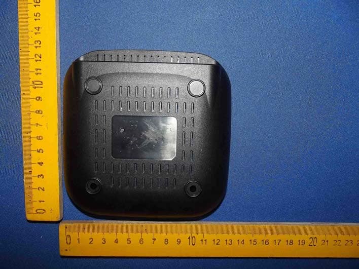
Click to zoom
Application Details
- Equipment Class
- DTS - Digital Transmission System
- Date of Grant
- May 26, 2014
- Application Purpose
- Original Equipment
- Date of Application
- May 26, 2014
- Equipment Note
- SMART TV BOX
- Frequency Range
- 2422.00000000 - 2452.00000000
- Country
- China
Documents & Files
Document Text
Text extracted from the exhibit documents filed with the FCC. Open a document above to read the original.
Users Manual
TT TV BOX 4X CPU Cortex-A9 8X GPU Mali-450 4kX2k DRM 3D-HD 1080Px2 User Manual 2HD wmv Matpewka MATROSKA Flash 10.2 Digital out x2 Android 4.4 KitKat Preface Thanks very much for choosing our TV Box.In order to make it more convenient for you to use proficiently, we provide you with a user manual. Please read it carefully before using and properly keep it for reference. Statements We have made every effort to provide the most current information about the product. We do not grant any guarantees as to the contents of the present instruction manual and disclaim any implied guarantees concerning market value or suitability for specific purposes. The information contained here is an instruction intended to enable the correct usage and maintenance of the receiver. We reserve itself the right to introduce amendments, changes or translations of the use rmanual without prior notification thereof. For this reason, we recommend you regularly visit our website in order to obtain the latest information. 1 1 01 TTTV BOX 02 TT TV BOX 02 02 02 03 04 04 05 06 07 07 08 08 09 09 10 10 11 11 12 12 13 14 16 16 15 1. 1 Key Features 1. 2 Environment for System 1. 3 Package Contents 2. 1 Introduction of Remote 3. 1 AV Connection 3. 2 HDMI Connection 3. 3 Startup 5.1 Email 5.2 Calculator 5.3 PPPoE 5.4 Browser 5.5 Movie Player 5.6 Media Centre 5.7 Gallery 5.8 Samba 5.9 File Browser 5.10 Download 5.11 Music 5.12 App Installer 5.13 Muti-interaction 5.14 OTA update 6.1 Network 6.2 Display 6.3 Advanced 6.4 Other Chapter 1 System Introduction Chapter 2 Remote Controller Chapter 3 System Connection Chapter 4 Home Chapter 5 Apps Chapter 6 Settings Chapter 7 Trouble Shotting Chapter 8 Specification Contents Chapter 1 System Introduction 1. 1 Key Features Android 4.4 operating system with Quad-Core Cortex-A9r4, 2.0GHz Support many kinds of IPTV and OTT TV programmes. Support three main HD formats:VC-1,H.264,MPEG-2 and many other normal formats such as MPEG-1、MPEG-2、MPEG-4、DIVX、REALMEDIA and so on. Video formats include avi, mpg, vob, rmvb, mkv, m2ts ,ts and so on. Photo formats include JPEG, BMP, and PNG up to 80M pixels. Audio formats include MP3、WMA、WAV、AC3、DTS、AAC and so on. Support SD/SDHC/MMC cards. Support two USB 2.0 host connectors with maximum output current of 1.5A/5V. Support standard RJ45 cable network connection and wireless network connection. Support infrared remote controller operation. Operation : Temperature limitation: 0--40°C; Humidity limitation: 20--80%。 Storage : Temperature limitation: -20--50°C; Humidity limitation: 10--90%。 1. 2 Environment for System 1. 3 Package Contents AccessoriesQuantity Power adaptor Remote control 1 1 HDMI cable User manual TTTV BOX 04 TT TV BOX AV 03 Power:Press to turn on/off Chapter 2 Remote Controller 2. 1 Introduction of Remote Website:Press to enter the browser Mute:Press to turn down the volume Vol:Press to increase/decrease the volume Navigation:Press to navigate left/right/up/down. Press OK to confirm your choose. MENU:Press to choose function menu of corresponding application in video,music,photo and website. Home:Press to get back the main menu. Return:Press to return back to previous menu Number:Press to choose the number. Backspace:Press to backspace the input. Mouse:Press to use the navigation button as mouse. Chapter 3 System Connection 3. 1 AV Connection 3. 2 HDMI Connection connect with TVconnect with TV HDMI cableAV cable Ethernet cable Router Power adaptor 05 TTTV BOX 06 TT TV BOX 3.3 Startup Turn on the TV box while indicator light is blue. Enter into main menu at about 30 seconds. Chapter 4 Home There are apps which you usual use. You can add the apps according to your own preference. Please tick the apps you need. Tick it again when you don’t need it. Chapter 5 My Apps Move to “My Apps”,Press OK to enter in. You can see icons referring to different function on the picture. 5.1 Email Move to “Email”. Press OK to enter in. It is a convenient way for you to send and receive your emails. You can configure Email for most accounts in just a few steps. Move to Email address. Press to input your email address and password. And press the icon “next”. 07 TTTV BOX 08 TT TV BOX 5.2 Calculator Move to “Calculator” icon. Press OK to enter in. It is a simple calculator for arithmetical workings. 5.3 PPPoE Move to “PPPoE”icon,Press OK to enter in.You can configure PPPoE here. 5.4 Browser Move to “Browser”. Press OK to enter in. It is a convenient way for you to go to your desired website. Notice: Please go to the system setting to set the internet connection before entering into the website. 5.5 Movie Player Move “Movie Player”. Press OK to enter into the movie list. 09 TTTV BOX 10 TT TV BOX 5.6 Media Centre Move to “Media Centre ”icon,You can play all your prefer media here. 5.7 Gallery Move to “Gallery”. Press OK to enter into the picture list Here you can enjoy the pictures 5.8 Samba Move to “Samba”. Press OK to enter in. The system will search the share files automatically. 5.9 File Browser Move to “Filebrowser” . Press OK to enter into the device list. When inserting with USB device or SD/SDHC/MMC cards,the sign“Device is mounting”will be shown on the screen. Here you can cut,copy,paste and move the files and folder betweenthe local disk and external storage card. 11 TTTV BOX 12 TT TV BOX 5.10 Download Move to “Downloads”. Press OK to enter in. You can check the status here when downloading apks from the internet. 5.11 Music Move to “Music”. Press OK to enter into the music list.This is for local media player. can enjoy beautiful music. Here you 5.12 App Installer Move to “App Installer”. Press OK to enter in. You can install software by this appinstaller function. Please first download your desired software by apk formats from the computer to the USB. You will choose your desired device in order to scan the apks. Press OK to install your desired software. After the installation finished, the software icon will be shown on the applications menu. 5.13 Muti-inter…
Text truncated - open the document above for the full version.
Cover Letter(s)
Shenzhen Shiningworth Technology Co., Ltd. FCC Confidentiality Request Number:CF303 Version:V05 Date: 21-05-2012 (Permanent or also called long term confidentiality is the normal method to keep certain docuements confidential, and may apply to schematics, block diagrams, operational description and bill of materials.) To: Federal Communications Commission Equipment Authorization Branch 7435 Oakland Mills Road Columbia, MD 21046 Pursuant to 47 CFR Section 0.459(a) & (b), we, (the applicant / grantee) Company nameShenzhen Shiningworth Technology Co., Ltd. AddressRoom 610-613, Block B, Huameiju Business Center, Xinhu Road, Baoan District, CityShenzhen, Guangdong, CountryChina request for this certification filing under: Grantee CodeProduct Number FCC ID:2ACFB-M9 to maintainpermanent confidentialityfor the following documents submitted within this application: (please cross what is applicable, or add other documents, provide the file name and description) ExhibitFile NameDescription √ Operational DescriptionOperational Descriptionexplaining the functioning of the block diagram √ Block DiagramsBlock Diagramsshowing the systematic building blocks of the EUT √ Schematics DiagramsSchematicsshowing components, their values and interconnection Bill of MaterialsList of components used on the PCB’s of the EUT Above materials crossed contain secrets, proprietary and technical information, which would customarily be guarded from competitors under 47 CFR, section 0.457(d)(2). Disclosure or publication or any portion of this company confidential material to other parties could cause substantial competitive harm and provide unjustified benefits for competitors. We understand that pursuant to 47 CFR section 0.457(d)(1)(ii) disclosure of the applicant and all accompanying documentation will not be made before the date of the grant. The documents indicated as confidential above, are not publicly available elsewhere. Attestation: City and Country:Date:Name: (this must be a person) Function:Signature: (or official company stamp) Shenzhen, China2014-05-15 Sam KwokHardware Manager
External Photos
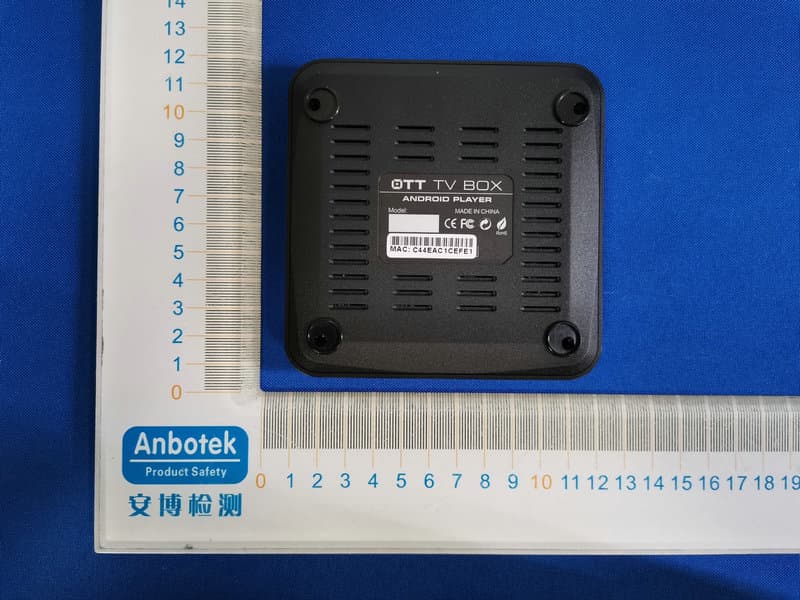
Figure 1 The EUT-Overall View Figure 2 The EUT-Front View Figure 3 The EUT- Back View Figure 4 TheEUT-SideView Figure 5 TheEUT-SideView
ID Label/Location Info
Label Location On EUT
ID Label/Location Info
Shenzhen Shiningworth Technology Co., Ltd.
Internal Photos
Figure 6 TheEUT-InsideView Figure 7 PCB of the EUT-Front View Figure 8 PCB of the EUT-Back View Figure 9 PCB of the EUT-Back View Figure 10 PCB of the EUT-Front View Figure 11 PCB of the EUT-Back View
RF Exposure Info
MPE Calculation FCC ID: 2ACFB-M9 EUT Description: SMART TV BOX Typical use distance: d ≥ 20 cm Power density limit for mobile devices at 2.4GHz: S ≤ 1 mW/cm 2 Remark: Average ≤ Peak, which means that calculating the power density applying Peak power is worst case. The worst case operation mode generating the highest power in each frequency range is taken for calculation. Frequency range: 2412-2462MHz, 2422-2452 Maximum measured conducted power (Peak): P conducted = 18.29 dBm = 67.5 mW Antenna Gain: G = 1 dBi Calculation: P radiated = P conducted + G linear = 18.29 dBm + 1 dBi = 19.29 dBm = 84.92 mW Power density S = (P radiated ) / (4π x d 2 ) = 84.92 / 5026 =0.0169 mW/cm 2 is below the limit, so pass.
Test Report
Shenzhen Anbotek Compliance Laboratory Limited FCC ID: 2ACFB-M9 Page 1 of 91 Report No.: 201403962F Shenzhen Anbotek Compliance Laboratory Limited Tel:(86)755-26066544 Fax:(86)755-26014772 www.anbotek.com FCC TEST REPORT for Shenzhen Shiningworth Technology Co., Ltd. SMART TV BOX Model No.: M6, M8, M9, M10, M12, M16, M18, M28, S8 Report Number: 201403962F Date of Test:Apr. 01 ~May15, 2014 Date of Report:Ma y16, 2014 Prepared fo r: Shenzhen Shiningworth Technology Co., Ltd. Address: Room 610-613, Block B, Huameiju Business Center, Xinhu Road, Baoan District, Shenzhen, Guangdong, China Prepared By: Shenzhen AnbotekCompliance Laboratory Limite d Address: 1/F., Building 1, SEC Industrial Park, No.0409 Qianhai Road, Nanshan District, Shenzhen, Guangdong, China Tel: (86) 755-26066544 Fax: (86) 755-26014772 Shenzhen Anbotek Compliance Laboratory Limited FCC ID: 2ACFB-M9 Page 2 of 91 Report No.: 201403962F Shenzhen Anbotek Compliance Laboratory Limited Tel:(86)755-26066544 Fax:(86)755-26014772 www.anbotek.com TABLE OF CONTENT Description Page Test Report 1. GENERAL INFORMATION......................................................................................................4 1.1. Description of Device (EUT)................................................................................................................4 1.2. Auxiliary Equipment Used during Test................................................................................................ 5 1.3. Description of Test Facility.................................................................................................................. 6 1.4. Measurement Uncertainty.....................................................................................................................6 2. TEST METHODOLOGY............................................................................................................7 2.1. Summary of Test Results......................................................................................................................7 2.2. Description of Test Modes....................................................................................................................7 2.3. List of channels:....................................................................................................................................8 3. CONDUCTED EMISSION TEST.............................................................................................. 9 3.1. Block Diagram of Test Setup................................................................................................................9 3.2. Power Line Conducted Emission Measurement Limits (15.207).........................................................9 3.3. Configuration of EUT on Measurement............................................................................................... 9 3.4. Operating Condition of EUT................................................................................................................ 9 3.5. Test Procedure.................................................................................................................................... 10 3.6. Test equipment....................................................................................................................................10 3.7. Power Line Conducted Emission Measurement Results.................................................................... 10 4. FCC PART 15.247 REQUIREMENTS FOR DSSS & OFDM MODULATION................. 13 4.1 Test Setup.............................................................................................................................................13 4.2 6dB Bandwidth.................................................................................................................................... 13 4.3. Maximum Peak output power test...................................................................................................... 21 4.4. Band Edges Measurement...................................................................................................................29 4.5. Peak Power Spectral Density..............................................................................................................66 4.6. Radiated Emissions.............................................................................................................................74 5. PHOTOGRAPH......................................................................................................................... 85 5.1. Photo of Conducted Emission Measurement......................................................................................85 5.2. Photo of Radiation Emission Test.......................................................................................................85 APPENDIX I (EXTERNAL PHOTOS)........................................................................................86 APPENDIXII(INTERNAL PHOTOS)...................................................................................... 89 Appendix I (3 Pages) Appendix II (3 Pages) Shenzhen Anbotek Compliance Laboratory Limited FCC ID: 2ACFB-M9 Page 3 of 91 Report No.: 201403962F Shenzhen Anbotek Compliance Laboratory Limited Tel:(86)755-26066544 Fax:(86)755-26014772 www.anbotek.com TEST REPORT Applicant: Shenzhen Shiningworth Technology Co., Ltd. Manufacturer: Shenzhen Shiningworth Technology Co., Ltd. EUT: SMART TV BOX Model No.: M6, M8, M9, M10, M12, M16, M18, M28, S8 Serial No.: N.A. Trade Mark: N.A. Rating: DC 5V, 10W, 2000mA Measurement Procedure Used: FCC Part15 Subpart C, Paragraph 15.247 The device described above is tested by Shenzhen Anbotek Compliance Laboratory Limited to determine the maximum emissionlevels emanating from the device and the severe levels of the device can endure and itsperformance criterion. The measurement results are contained in this test report andShenzhen Anbotek Compliance Laboratory Limited is assumed…
Text truncated - open the document above for the full version.
Contact Information
Applicant
Sam Kwok(Hardware Manager)
Technical Contact
Test Firm
Shenzhen Anbotek Compliance Laboratory LimitedDaniel zhu
[email protected]86-755-26014771
Technical Specifications
| # | Rule Parts | Frequency Range | Power Output |
|---|---|---|---|
| 2 | 15C | 2.42 GHz - 2.45 GHz | 50.40 mW |
Other Applications from Shenzhen Shiningworth Technology Co., Ltd.
2ACFBM6CX3-D4
Jan 16, 2020smart tv box
Equipment Class
DTS - Digital Transmission System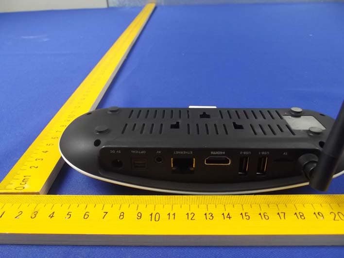
2ACFB-S6
Jun 03, 2014Smart TV Box
Equipment Class
DTS - Digital Transmission System