2ACH4SONWP2Wireless Remote
Sonatest AP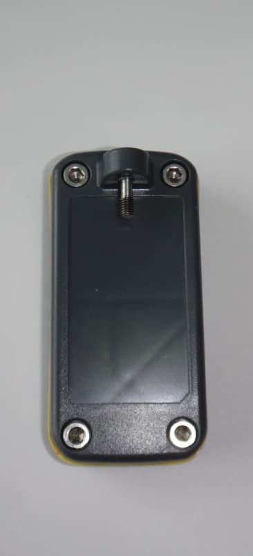
Click to zoom
Application Details
- Equipment Class
- DSC - Part 15 Security/Remote Control Transmitter
- Date of Grant
- Apr 20, 2015
- Application Purpose
- Original Equipment
- Date of Application
- Apr 20, 2015
- Equipment Note
- Wireless Remote
- Frequency Range
- 433.92000000 - 433.92000000
- Company
- Sonatest AP
- Country
- Canada
Documents & Files
Document Text
Text extracted from the exhibit documents filed with the FCC. Open a document above to read the original.
Users Manual
Sonatest WP2 Wheel Probe User Manual v Copyright © 2015 Sonatest Limited 2015-03-16 Copyright © 2015 Sonatest Limited - 2015-03-16 iii Table of Contents Table of Contents 1 Disclaimers and Notices1 1.1 Copyright ..............................................................................................................1 1.2 Warranty ...............................................................................................................1 1.3 Equipment Directive Conformance ....................................................................2 2 Introduction5 2.1 WP2 Compatibility ...............................................................................................5 2.2 Connection and Remote Control Compatibility ................................................5 2.3 Operator Requirements.......................................................................................6 2.4 Operating Conditions ..........................................................................................6 3 Product Overview7 3.1 Components .........................................................................................................7 3.2 Handles .................................................................................................................7 3.3 Cable Options and Connectors ..........................................................................8 3.4 Roller Options ......................................................................................................9 3.5 Wireless Remote Control ..................................................................................11 3.6 Status LEDs........................................................................................................12 3.7 Transportation Case and Standard Accessories............................................13 3.8 Laser Guidance Kit ............................................................................................13 3.9 Remote Display Kit ............................................................................................14 4 Setting up the WP215 5 Connecting the WP217 5.1 Connecting the WP2 to Sonatest Test Instruments .......................................17 5.2 Connecting the WP2 to Instruments from Other Manufacturers ..................20 6 Performing an Inspection23 7 Acoustic Recommendations25 7.1 Interface triggering (Zero Synchronization) ....................................................25 7.2 Material Velocity Calibration.............................................................................26 Copyright © 2015 Sonatest Limited - 2015-03-16 Sonatest WP2 - User Manual iv 7.3 TCG and Sensitivity Calibration ...................................................................... 26 7.4 Extractor Box Function .................................................................................... 29 7.5 Extracting C-scans from Gates........................................................................ 30 8 Maintenance33 8.1 Refilling the Wheel with Water ......................................................................... 33 8.2 Verification of the Tyre ..................................................................................... 33 8.3 Replacement of the Remote Control Battery.................................................. 34 8.4 Pairing the Remote Control with the WP2 ...................................................... 35 8.5 Replacing the Tyre ............................................................................................ 36 8.6 Contact Support ................................................................................................ 38 9 Product Specifications41 Copyright © 2015 Sonatest Limited - 2015-03-16 1 Disclaimers and Notices 1 Disclaimers and Notices The following information must be read and understood by users of the rolling transducer WP2 wheel probe. Failure to follow these instructions can lead to serious errors in test results or damage to the probe. Decisions based on erroneous results can lead to property damage, personal injury, or death. Anyone using this instrument should be fully qualified by their organization in the theory and practice of ultrasonic testing, or under the direct supervision of such a person. All statements, technical information, and recommendations contained in this manual or any other information supplied by Sonatest concerning the use, features, and qualification of the WP2 are based on tests believed to be reliable. However, the accuracy or completeness of the information is not guaranteed. Before using the product users should determine its suitability for the intended use based on their knowledge of ultrasonic testing and the characteristic of materials. Users bear all risk in connection with the use of the WP2 wheel probe. 1.1 Copyright Copyright © 2012 Sonatest Limited All rights reserved. No part of this publication may be reproduced, stored in a retrieval system or transmitted in any form or by any means, electronic, mechanical, photocopying, recording or otherwise, without the prior written permission of Sonatest Limited. 1.2 Warranty Immediately upon receipt of the goods, the buyer is required to check the goods carefully and thoroughly in order to benefit from the warranty; any defect in the product should be immediately reported in writing to Sonatest. We will make good by repair or by the supply of a replacement or by equivalent adjustment of the price at our sole option defects which under proper use appear in the goods within a period of twelve (12) calendar months after the goods have been delivered and which arise solely from faulty design, material or workmanship. Provided always that the goods are carefully packed and promptly returned by you free to our works unless otherwise arranged. Said goods should be covered while in transit to us and must be accompanied by a written statement detailing the precise nature of the fault and the operating conditi…
Text truncated - open the document above for the full version.
Users Manual
Copyright © 2015 Sonatest Limited - 2015-03-16 17 Connecting the WP2 5 Connecting the WP2 This section presents the connections between the Sonatest WP2 wheel probe to Sonatest test instruments and instruments from other manufacturers. The Sonatest test instruments include: •veo •Prisma •RapidScan2 5.1 Connecting the WP2 to Sonatest Test Instruments To connect the WP2 to the veo, the Prisma, and the RapidScan2, connect the wheel-probe side of the cable to the WP2 and connect the instrument side of the cable to the test instrument. To connect the cable to the WP2: 1 Connect the phased array connector to the Samtec connector and fasten it using the thumbscrews. 2 Connect the 10-pin Lemo to the Encoder/GPIO connector located next to the Samtec connector. Figure 5-1 WP2 connectors To connect the cable to the veo: 1 Unscrew the protective cap on the right side of the instrument and place it on the back of the unit (over the CE markings). 2 Connect the phased array connector to the Samtec connector and secure it with the hand screws. Phased array connector (Samtec) Connector thumb screwsEncoder/GPIO connector (Lemo) Copyright © 2015 Sonatest Limited - 2015-03-16 Sonatest WP2 - User Manual 18 Figure 5-2 Connectors on the right side of the veo 3 Connect the 8-pin Lemo connector to the encoder input (S connector on the right side of the veo). 4 Connect the GPIO, 8-pin, Lemo to the I/O input (I/O connector on the right side of the veo). 5 Turn on the veo and, on the Inspection tab, select Wheel Probe 2 in the GPIO list. To connect the cable to the Prisma: 1 Unscrew the protective cap on the right side of the instrument and place it on the back of the unit (over the CE markings). 2 Connect the phased array connector to the I-PEX connector and secure it with the hand screws. Phased array connector (Samtec) I/O connector S connector Copyright © 2015 Sonatest Limited - 2015-03-16 19 Connecting the WP2 Figure 5-3 Connectors on the right and back sides of the Prisma 3 Connect the 8-pin Lemo connector to the encoder input (E connector on the back side of the Prisma). 4 Connect the GPIO, 8-pin, Lemo to the I/O input (I/O connector on the back side of the Prisma). 5 Turn on the Prisma and, on the Inspection tab, select Wheel Probe 2 in the GPIO list. To connect the cable to the RapidScan2: 1 On the multi-way connector, turn the black handle to the open position. 2 Connect the multi-way connector on the RapidScan2 panel. The connector should offer no resistance. If the connector does not easily fit, verify the condition of the connector pins. 3 Once the multi-way connector is installed, turn the black handle to lock it in place. 4 Connect the 7-pin to 8-pin Lemo adaptor to the multi-way connector. 5 Connect the 8-pin Lemo (encoder) connector to the adapter. Phased array connector (I-PEX) I/O connector E connector Copyright © 2015 Sonatest Limited - 2015-03-16 Sonatest WP2 - User Manual 20 Figure 5-4 Connection to the RapidScan2 5.2 Connecting the WP2 to Instruments from Other Manufacturers To connect the WP2 to the Olympus OmniScan MX2 or MX, connect the wheel-probe side of the cable to the WP2 and connect the instrument side of the cable to the test instrument. To connect the cable to the WP2: 1 Connect the phased array connector to the Samtec connector and fasten it using the thumbscrews. 2 Connect the 10-pin Lemo to the Encoder/GPIO connector located next to the Samtec connector. Figure 5-5 WP2 connectors To connect the cable to the OmniScan: 1 Connect the phased array connector to the I-PEX connector and secure it with the hand screws. 2 Connect the Lemo GPIO and Encoder connectors to the adaptor box. 7-pin to 8-pin Lemo adaptor Black handle Multi-way connector 8-pin Lemo connector (encoder) Phased array connector (Samtec) Connector thumb screwsEncoder/GPIO connector (Lemo) Copyright © 2015 Sonatest Limited - 2015-03-16 21 Connecting the WP2 3 Connect the GPIO DB-9 to the Olympus instrument. 4 Connect the encoder HD-15 to the adaptor output box. With the OmniScan MX2, the HD15 to Lemo-16 adaptor is required. Tips for a basic setup in OmniScan Set the inspection plan to raster scan. Select the encoder 1 as quadrature. Select the encoder 2 as a clicker and steps as your index step. In Preferences, set Din1 for the Reset Scan position. Set Din2 to None because it is a clicker. Set Din3 to Acquisition Enable. In the Gate/Alarm settings, set alarm 1 for gate A and alarm 2 for gate B. On the Output menu, set gates A and B as outputs 1 and 2 respectively. Copyright © 2015 Sonatest Limited - 2015-03-16 Sonatest WP2 - User Manual 22 Copyright © 2015 Sonatest Limited - 2015-03-16 23 Performing an Inspection 6 Performing an Inspection This section presents the procedures to perform an inspection using the WP2 wheel probe and Sonatest veo, Prisma, and RapidScan2. Figure 6-1 Copyright © 2015 Sonatest Limited - 2015-03-16 Sonatest WP2 - User Manual 24 Copyright © 2015 Sonatest Limited - 2015-03-16 25 Acoustic Recommendations 7 Acoustic Recommendations This section presents the acoustic recommendations while scanning with the WP2. It provides information about settings, calibrations and data extraction for both veo and Prisma test instruments. 7.1 Interface triggering (Zero Synchronization) The interface triggering is used to modify the reception of ultrasound signals. When set to Yes, the IFT Active item enables the part interface triggering for this scan. It is available for the following types or primary scans: •A-scan (mono) •L-scan (phased array) Once enabled, a new gate (white named "I") is made available in the A-scan view. Interface triggering is used to synchronize signal interface when it varies from one beam to another. This corrects the distance between the probe and the part when the wedge does not have a fixed height. This feature overcomes delay variations due to the tyre deformation. To set the interface triggering: 1 On the test instrument, press the key. 2 Select the Scan tab and, on the Scan menu, s…
Text truncated - open the document above for the full version.
Operational Description
11‐ Operational description The Wireless Remote is made to wirelessly transfer commands to the main ultrasound device through the WheelProbe 2. There are three push‐buttons used to transmit the following commands: Record/Stop, Next Index, Reset Encoder Position. If desired, these commands can be entered directly on the ultrasound device. The Wireless Remote is powered from a 3 V CR2032 button cell and transmit data at a 433.92 MHz frequency. It is based on Linx technologies’ encoder (MS series) and transmitter (LR series). The encoder is configured to use a 9600 baudrate. Whenever a button is pressed, the encoder wakes up, encode the pressed button, send it to the transmitter as long as the button is pressed and go back to sleep when the button is released. When the transmitter receives the encoded data, it wirelessly sends the data to the WheelProbe 2 which relays the command to the ultrasound device through its GPIO connector.
Test Report
Nemko Canada Inc., a testing laboratory, is accredited by the Standards Council of Canada. The tests included in this report are within the scope of this accreditation www.nemko.com FCC and IC 433 MHz.docx; Date: June, 2013 SCC Accredited LAB LAB Accrédité CCN TM ONE WORLDOURAPPROVAL Test report 259622-1TRFWL Date of issue: April 16, 2015 Applicant: Sonatest AP Inc. Product: 64 Elements – 5MHz Model: WP2 FCC ID: IC Registration number: 2ACH4SONWP2 12048A-SONWP2 Specification: FCC 47 CFR Part 15, Subpart C, Chapter 15.231 Periodic operation in the band 40.66–40.70 MHz and above 70 MHz RSS-210, Issue 8 Annex 1.1 Momentarily operated devices Report reference ID: 259622-1TRFWL Page 3 of 22 Test location Company name: Nemko Canada Inc. Address: 303 River Road City: Ottawa Province: Ontario Postal code: K1V 1H2 Country: Canada Telephone: +1 613 737 9680 Facsimile: +1 613 737 9691 Toll free: +1 800 563 6336 FCC site ID: 176392 IC site ID: 2040A Website: www.nemko.com Tested by: Kevin Rose, Wireless/EMC Specialist Reviewed by: Andrey Adelberg, Senior Wireless/EMC Specialist Date: April 16, 2015 Signature: Limits of responsibility Note that the results contained in this report relate only to the items tested and were obtained in the period between the date of initial receipt of samples and the date of issue of the report. This test report has been completed in accordance with the requirements of ISO/IEC 17025. All results contain in this report are within Nemko Canada’s ISO/IEC 17025 accreditation. Copyright notification Nemko Canada Inc. authorizes the applicant to reproduce this report provided it is reproduced in its entirety and for use by the company’s employees only. Any use which a third party makes of this report, or any reliance on or decisions to be made based on it, are the responsibility of such third parties. Nemko Canada Inc. accepts no responsibility for damages, if any, suffered by any third party as a result of decisions made or actions based on this report. © Nemko Canada Inc. Report reference ID: 259622-1TRFWL Page 4 of 22 Table of Contents Table of Contents .......................................................................................................................................................................................... 4 Section 1 Report summary .................................................................................................................................................................... 5 1.1 Applicant ........................................................................................................................................................................................... 5 1.2 Manufacturer ..................................................................................................................................................................................... 5 1.3 Test specifications ............................................................................................................................................................................ 5 1.4 Statement of compliance ................................................................................................................................................................... 5 1.5 Test report revision history ................................................................................................................................................................ 5 Section 2 Summary of test results ........................................................................................................................................................ 6 2.1 FCC Part 15 Subpart C – Intentional Radiators, test results .............................................................................................................. 6 2.2 RSS-210, Issue 8 Annex 1.1, test results .......................................................................................................................................... 6 Section 3 Equipment under test (EUT) details ..................................................................................................................................... 7 3.1 Sample information ........................................................................................................................................................................... 7 3.2 EUT information ................................................................................................................................................................................ 7 3.3 EUT technical specifications ............................................................................................................................................................. 7 3.4 Operation of the EUT during testing .................................................................................................................................................. 8 3.5 EUT setup details .............................................................................................................................................................................. 9 Section 4 Engineering considerations ............................................................................................................................................... 10 4.1 Modifications incorporated in the EUT ............................................................................................................................................. 10 4.2 Technical judgment ......................................................................................................................................................................... 10 4.3 Deviations from laboratory tests procedures ................................................................................................................................... 10 Section 5 Test conditions ..............................…
Text truncated - open the document above for the full version.
Test Setup Photos
www.nemko.com Nemko Canada Inc., a testing laboratory, is accredited by the Standards Council of Canada. The tests included in this report are within the scope of this accreditation setup photos.docx; Date: May 2013 SCC Accredited LAB LAB Accrédité CCN TM ONE WORLDOURAPPROVAL Setup photos 259622-3RADWL Date of issue: July 10, 2014 Applicant: Sonatest AP Inc. Product: WheelProbe 2 Model: 64 Elements – 5MHz FCC ID: IC Registration number: 2ACH4SONWP2 12048A-SONWP2 Section 1: Setup photos Report reference ID: -2RADWL Page 2 of 2 Section 1. Setup photos 1.1 Radiated Emissions
Contact Information
Applicant
Yvan Gosselin(Technical Director)
Test Firm
Nemko Canada Inc. (Ottawa)Charles Neal
Technical Specifications
| # | Rule Parts | Frequency Range | Power Output |
|---|---|---|---|
| 1 | 15.231(e) | 433.92 MHz - 433.92 MHz | - |