2ACJGR300TRouter inalambrico N300
TECHVIEW,INC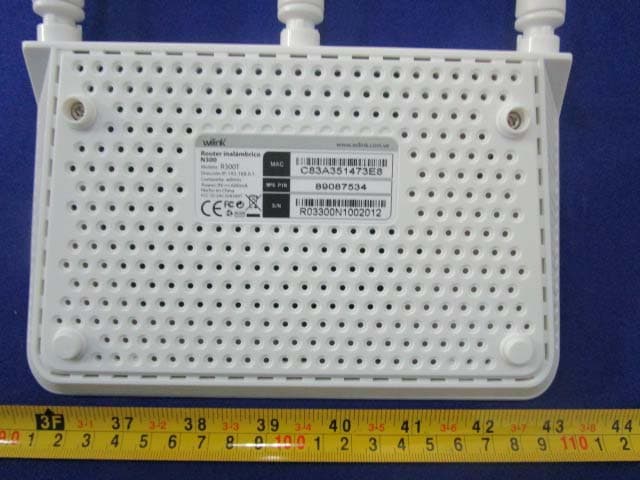
Click to zoom
Application Details
- Equipment Class
- DTS - Digital Transmission System
- Date of Grant
- Oct 26, 2014
- Application Purpose
- Original Equipment
- Date of Application
- Oct 26, 2014
- Equipment Note
- Router inalambrico N300
- Frequency Range
- 2422.00000000 - 2452.00000000
- Company
- TECHVIEW,INC
- Country
- United States
Documents & Files
Document Text
Text extracted from the exhibit documents filed with the FCC. Open a document above to read the original.
Users Manual
User Guide www.wilinklat.com Copyright Statement is the registered trademark of Techview Inc. All the products and product names mentioned herein are the trademarks or registered trademarks of their respective holders. Copyright of the whole product as integration, including its accessories and software, belongs to Techview Inc. Without prior expressed written permission from Techview Inc., any individual or party is not allowed to copy, plagiarize, reproduce, or translate it into other languages. All photos and product specifications mentioned in this manual are for references only. Upgrades of software and hardware may occur; Wilink reserves the right to revise this publication and to make changes in the content hereof without obligation to notify any person or organization of such revisions or changes. If you would like to know more about our product information, please visit our website at http://www.wilinklat.com. Table of Contents TABLE OF CONTENTS........................................................................2 CHAPTER 1 PRODUCT OVERVIEW............................................................1 1.1 P ACKAGE C ONTENTS ............................................................................................................1 1.2 G ETTING TO KNOW YOUR ROUTER .......................................................................................1 CHAPTER 2 INSTALLATION AND QUICK SETUP GUIDE..............................5 2.1 P REPARATION .....................................................................................................................5 2.2 P HYSICAL INSTALLATION ......................................................................................................5 2.3 I NTERNET C ONNECTION S ETUP ...........................................................................................7 2.3.1 Use Standard TCP/IP Properties for DHCP............................................................7 2.3.2 Log in to Web Manager..............................................................................................7 2.3.3 Quick Internet Connection Setup............................................................................8 2.3.4 Verify Internet Connection Settings........................................................................9 2.3.5 Wireless Settings......................................................................................................11 2.3.6 Connect to Device Wirelessly..............................................................................12 CHAPTER 3 ADVANCED SETTINGS.........................................................20 3.1 S TATUS ...........................................................................................................................20 3.2 I NTERNET C ONNECTION S ETUP .......................................................................................21 3.2.1 PPPoE...........................................................................................................................21 3.2.2 Static IP.....................................................................................................................22 3.2.3 DHCP...........................................................................................................................23 3.2.4 PPTP...........................................................................................................................24 3.2.5 L2TP...........................................................................................................................25 3.3 MAC C LONE ......................................................................................................................26 3.4 WAN S PEED .....................................................................................................................26 3.5 WAN M EDIUM T YPE .........................................................................................................27 3.6 LAN S ETTINGS ..................................................................................................................30 3.7 DNS S ETTINGS ...............................................................................................................30 3.8 DHCP...............................................................................................................................31 3.9 DHCP C LIENT L IST .........................................................................................................31 CHAPTER 4 WIRELESS SETTINGS............................................................33 4.1 W IRELESS B ASIC S ETTINGS ..............................................................................................33 4.1.1 Wireless AP Mode......................................................................................................33 4.1.2 WDS Bridge Mode...................................................................................................35 4.2 W IRELESS S ECURITY .........................................................................................................43 4.3 W IRELESS A CCESS C ONTROL ..........................................................................................46 4.4 W IRELESS C LIENT ............................................................................................................47 CHAPTER 5 BANDWIDTH CONTROL.........................................................49 5.1 B ANDWIDTH C ONTROL ......................................................................................................49 5.2 T RAFFIC S TATISTICS .........................................................................................................50 CHAPTER 6 SPECIAL APPLICATIONS......................................................52 6.1 P ORT R ANGE F ORWARDING .............................................................................................52 6.2 DMZ H OST ..............................................…
Text truncated - open the document above for the full version.
Users Manual
37 3) Select the wireless network to connect and click OK. 4) Verify that the SSID, channel, and AP MAC address on the page match those of the added wireless network. If not, manually correct them. 38 5) Close Scan and click OK to save your settings. 39 6) Go to Wireless Security page and set the wireless security settings exactly as they are on the link partner (Router 1). 7) Go to DHCP Server to disable the DHCP on Router 2. Now you have finished all settings on Router 2 required for WDS. 40 2. Configure Router 1: 1) Go to wireless section on Router 1 and specify WDS (or WDS Bridge) as its wireless working mode. 2) Manually enter Router 2's MAC address (Also, you can use the Scan option as mentioned above) and click OK to finish your settings. 3. Configure PC3 and PC4 : 41 1) Set PC3 and PC4 to Obtain an IP address automatically. 2) When the two PCs get IP addresses, 42 try below steps to verify the WDS connection: Click Start-> Run on PC3, input cmd on the appearing window and then click OK. Input ping 192.168.0.1 and press Enter. If you get a screen as seen below, you have successfully implemented WDS. 43 Note: 1. WDS feature can only be implemented between 2 WDS-capable wireless devices. Plus, SSID, channel, security settings and security key must be exactly the same on both such devices. 2. To ensure a proper wireless connection, do not change any settings on the two devices after WDS is successfully implemented. 4.2 Wireless Security This section allows you to secure your wireless network and block unauthorized accesses and malicious packet sniffing. To encrypt your wireless network, do as follows: 1. Select the wireless network (SSID) you wish to encrypt. 2. Disable WPS. (WPS is enabled on the router by default. If you want to use other security modes, you must first disable the WPS.) 3. Select a proper security mode and cipher type (also known as WPA Algorithm or WPA Encryption Type). WPA-PSK and AES are recommended by system default. (5 security modes are available for your selection. Among them, WPA-PSK outstands with greater compatibility and security. For more information of other security modes, see appendix 2) Specify a security key that includes at least 8 characters. 4. Click OK to complete your settings. 44 WPS Wi-Fi Protected Setup makes it easy for home users who know little of wireless security to establish a home network, as well as to add new devices to an existing network without entering long passphrases or configuring complicated settings. Simply enter a PIN code or press the software PBC button or hardware WPS button (if any) and a secure wireless connection is established. Operation Instructions: PBC: To use WPS-PBC, try two ways below: 1) Press the hardware WPS button on the router for about 1 second and then enable WPS/PBC on the client device within 2 minutes; 2) Press the hardware WPS button on the router for about 1 second and then enable WPS/PBC on the client device within 2 minutes; PIN: On the wireless security page, enable WPS, select PIN and enter the 45 8-digit PIN code from network adapter; then, within 2 minutes, enable WPS/PIN on the client device; Note: 1. With WPS successfully enabled, the WPS LED on the router keeps blinking for about 2 minutes, and during this time, you can enable WPS on a wireless adapter; if the adapter successfully joins the wireless network, the WPS LED will display a solid light. Repeat steps above if you want to add more wireless adapters to the router. 2. Reset OOB: Clicking this button will reset SSID to factory default and disable security mode. 3. Existing wireless settings will still be maintained by default after a successful WPS connection. Namely security settings and SSID on the router will still be the same. If you want to generate a random wireless key via WPS, click Reset OOB and then follow WPS setup instructions above. 46 Note: 1. To use the WPS security, the wireless client must be also WPS-capable. 2. Before you press the hardware WPS button on the device for WPS/PBC connection, making sure the WPS feature has been enabled on the device. 4.3 Wireless Access Control The Access Control feature allows you to specify a list of devices to Permit or Forbid a connection to your wireless network via the devices’ MAC addresses. All other devices not listed as Permitted will be Forbidden and vice versa. 1. Select the wireless network (SSID) you wish to enable Access Control on. 2. MAC Address Filter: Select Permit or Forbid from the drop-down list. 3. To permit a wireless device to connect to your wireless network, select Permit (or Allow), enter its MAC address, click Add and then OK. Then 47 only this device listed as “Permitted” will be able to connect to your wireless network; all other wireless devices will forbidden. Step1. Select the wireless network (SSID) you wish to enable Access Control on. Step2. Select Permit from the corresponding drop-down menu. Step3. Enter the MAC address you wish to permit in the MAC address box and click Add. Step4. Click OK to save your settings. You can add more wireless MAC addresses you wish to allow. Example: To forbid the PC at the MAC address of C8:3A:35:65:82:E6 from connecting to your wireless network, do as follows: Step1. Select an SSID, say, Wilink_home. Step2. Select Forbid (or Deny) from the corresponding drop-down menu. Step3. Enter C8:3A:35:65:82:E6 in the MAC address box and click Add. Step4. Click OK to save your settings. You can add more wireless MAC addresses you wish to forbid. 4.4 Wireless Client Here you can see a list of wireless devices connected to the router, including their MAC addresses and bandwidth 48 Note: The bandwidth here refers to the channel bandwidth instead of wireless connection rate. 49 Chapter 5 Bandwidth Control 5.1 Bandwidth Control Use this section to manage bandwidth allocation to devices on your LAN. If there are multiple PCs behind your router competing for limited bandwidth resource, then you can use this feature to specify a rea…
Text truncated - open the document above for the full version.
External Photos
EXHIBIT B - EUT EXTERNAL PHOTOGRAPHS EUT – All View EUT – Top View EUT – Bottom View EUT –Side View EUT – Side View EUT – Port View EUT – Adapter View EUT –Adapter Side View EUT –Adapter Side View EUT –Adapter Label View
ID Label/Location Info
EXHIBIT A - FCC ID LABELING AND LOCATION FCC ID Label Proposed FCC ID Label Location The label shown shall be permanently affixed at a conspicuous location on the device and be readily visible to the user at the time purchase (Labeling requirements per 2.925) Label Here
Internal Photos
EXHIBIT C - EUT INTERNAL PHOTOGRAPHS EUT – Uncover View EUT – Main Board Top View EUT –Main Board Bottom View EUT –RF Chip View EUT –Antenna View
Test Report
Note: This test report is prepared for the customer shown above and for the device described herein. It may not be duplicated or used in part without prior written consent from Bay Area Compliance Laboratories Corp. (Dongguan). This report is valid only with a valid digital signature. The digital signature may be available only under the Adobe software above version 7.0. FCC PART 15.247 TEST REPORT For TECHVIEW, INC 8016 NW 68 STREET, MIAMI, FL33166, UNITED STATES FCC ID: 2ACJGR300T Report Type: Original Report Product Type: Router inalámbrico N300 Test En gineer: Dean Liu Re port Number: RDG140930008-00 Re port Date: 2014-10-17 Reviewed By: Sula Huang EMC Engineer Test Laboratory: Bay Area Compliance Laboratories Corp. (Dongguan) No.69 Pulongcun, Puxinhu Industrial Zone, Tangxia, Dongguan, Guangdong, China Tel: +86-769-86858888 Fax: +86-769-86858891 www.baclcorp.com.cn Bay Area Compliance Laboratories Corp. (Dongguan) Report No.: RDG140930008-00 FCC Part 15.247 Page 2 of 72 TABLE OF CONTENTS GENERAL INFORMATION ....................................................................................................................................... 4 PRODUCT DESCRIPTION FOR EQUIPMENT UNDER TEST (EUT) ..................................................................................... 4 OBJECTIVE ................................................................................................................................................................... 4 RELATED SUBMITTAL(S)/GRANT(S) ............................................................................................................................. 4 TEST METHODOLOGY .................................................................................................................................................. 4 TEST FACILITY ............................................................................................................................................................. 4 SYSTEM TEST CONFIGURATION .......................................................................................................................... 5 DESCRIPTION OF TEST CONFIGURATION ...................................................................................................................... 5 EQUIPMENT MODIFICATIONS ....................................................................................................................................... 5 EUT EXERCISE SOFTWARE .......................................................................................................................................... 5 SUPPORT EQUIPMENT LIST AND DETAILS .................................................................................................................... 6 EXTERNAL CABLE ........................................................................................................................................................ 6 BLOCK DIAGRAM OF TEST SETUP ................................................................................................................................ 6 SUMMARY OF TEST RESULTS ............................................................................................................................... 7 FCC §15.247 (i) & §1.1310 & §2.1091- MAXIMUM PERMISSIBLE EXPOSURE (MPE) ......................................... 8 APPLICABLE STANDARD .............................................................................................................................................. 8 FCC §15.203 - ANTENNA REQUIREMENT ............................................................................................................. 9 APPLICABLE STANDARD .............................................................................................................................................. 9 ANTENNA CONNECTOR CONSTRUCTION ...................................................................................................................... 9 FCC §15.207 (a) – AC LINE CONDUCTED EMISSIONS ..................................................................................... 10 APPLICABLE STANDARD ............................................................................................................................................ 10 MEASUREMENT UNCERTAINTY .................................................................................................................................. 10 EUT SETUP ................................................................................................................................................................ 10 EMI TEST RECEIVER SETUP ....................................................................................................................................... 11 TEST PROCEDURE ...................................................................................................................................................... 11 CORRECTED AMPLITUDE & MARGIN CALCULATION ................................................................................................. 11 TEST EQUIPMENT LIST AND DETAILS ......................................................................................................................... 12 TEST RESULTS SUMMARY .......................................................................................................................................... 12 TEST DATA ................................................................................................................................................................ 12 FCC §15.209, §15.205 & §15.247(d) - SPURIOUS EMISSIONS ............................................................................. 15 APPLICABLE STANDARD ............................................................................................................................................ 15 MEASUREMENT UNCERTAINTY ......................................................................................…
Text truncated - open the document above for the full version.
Test Setup Photos
EXHIBIT D - TEST SETUP PHOTOGRAPHS Conducted Emissions - Front View Conducted Emissions – Side View Radiated Emission Below 1GHz –Front View Radiated Emission Below 1GHz –Rear View Radiated Emission Above 1GHz-Front View Radiated Emission Above 1GHz-Rear View
Contact Information
Applicant
MIGUEL CIRCELLI(DIRECTOR)
Test Firm
Bay Area Compliance Laboratories Corp. (Dongguan)John Chan
[email protected]86-769-86858888
Technical Specifications
| # | Rule Parts | Frequency Range | Power Output |
|---|---|---|---|
| 2 | 15C | 2.42 GHz - 2.45 GHz | 380.00 mW |
Other Applications from TECHVIEW,INC
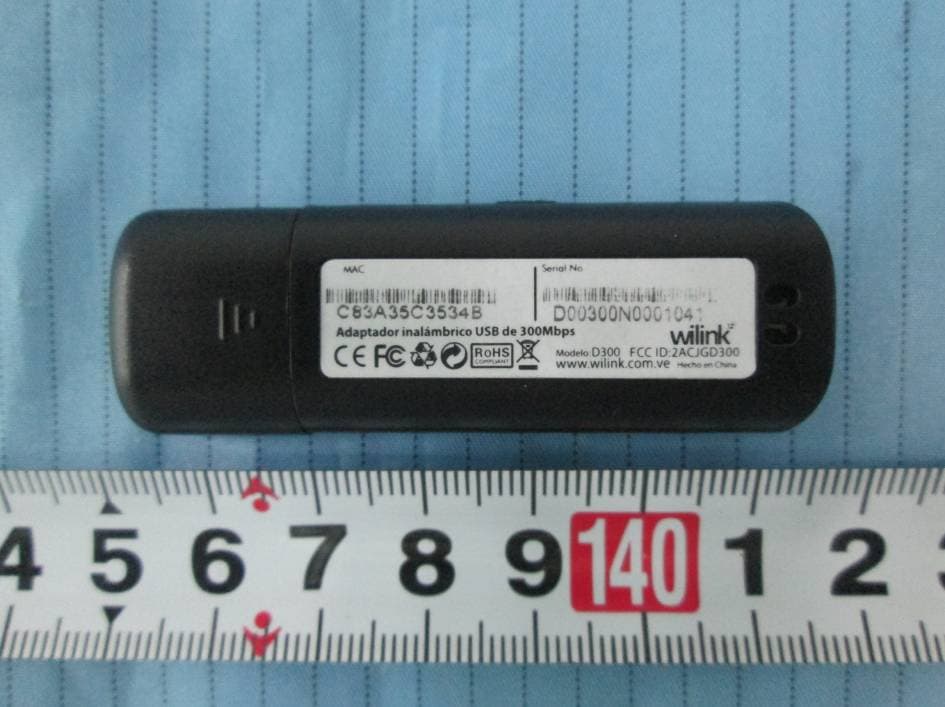
2ACJGD300
Nov 05, 2014Adaptador inalambrico USB de 300 Mbps
Equipment Class
DTS - Digital Transmission System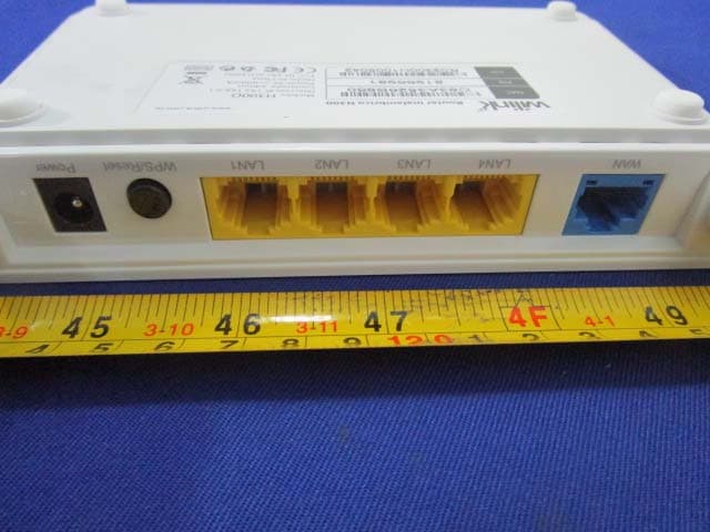
2ACJGH300D
Oct 24, 2014Router inalambrico N300
Equipment Class
DTS - Digital Transmission System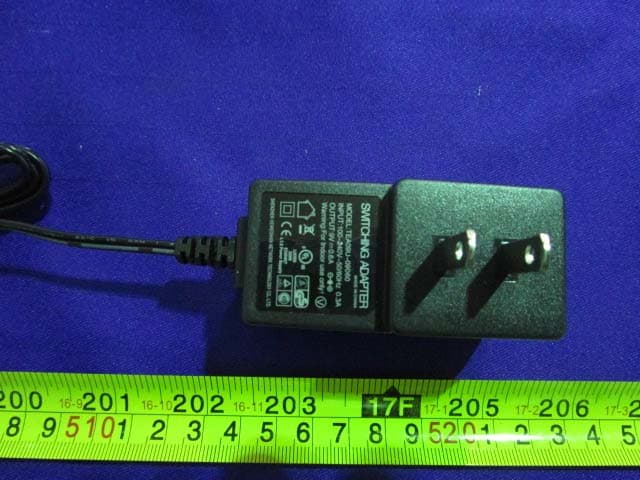
2ACJGR150S
Oct 24, 2014Router inalambrico N150
Equipment Class
DTS - Digital Transmission System