FCCID.CO- FCC ID Database
HomeCompaniesEquipment ClassesSearch

© 2026 FCC ID Database. All rights reserved.

AboutContactData sourced from FCC public records
  1. Home/
  2. CognitiveTPG, LLC/
  3. 2ACKK-0481401

2ACKK-0481401Bar Code Printer

CognitiveTPG, LLC
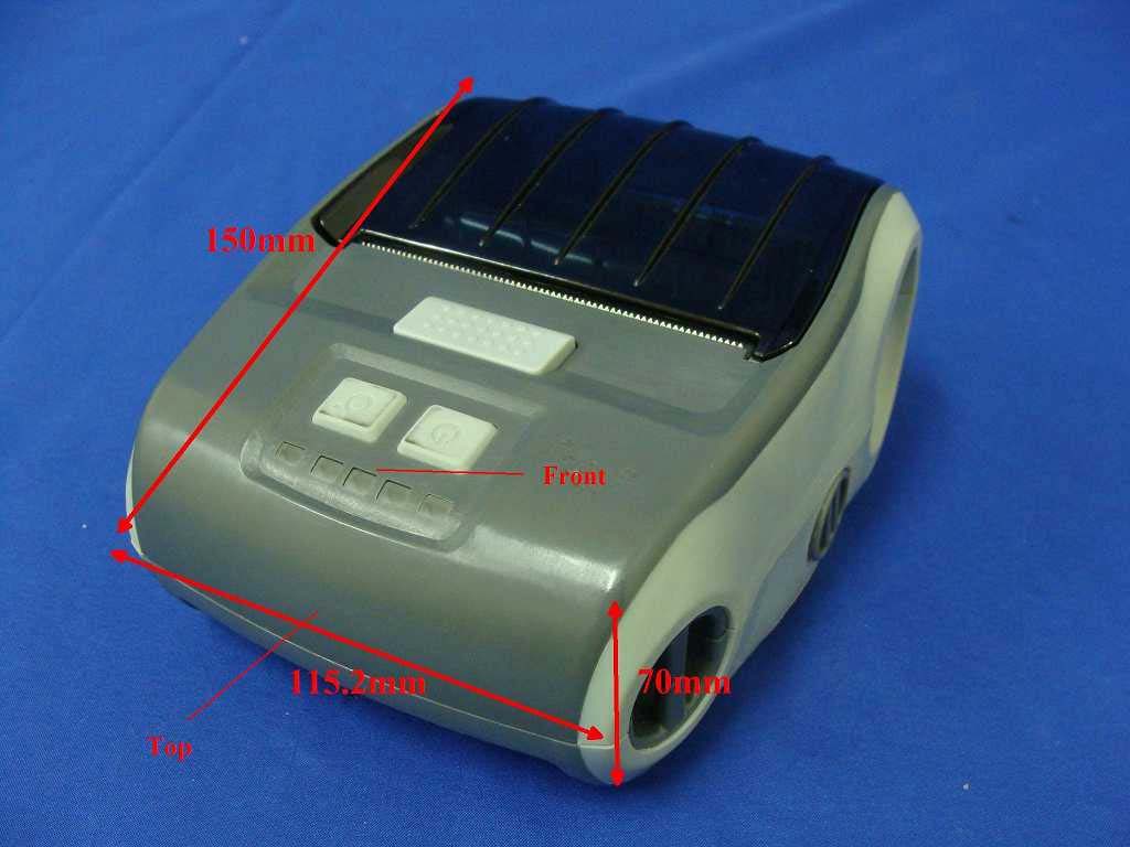
Bar Code Printer - FCC ID 2ACKK-0481401 - CognitiveTPG, LLC
Click to zoom

Application Details

Equipment Class
DSS - Part 15 Spread Spectrum Transmitter
Date of Grant
Jul 13, 2014
Application Purpose
Original Equipment
Date of Application
Jul 13, 2014
Equipment Note
Bar Code Printer
Frequency Range
2402.00000000 - 2480.00000000
Company
CognitiveTPG, LLC
Country
United States

Documents & Files

Select a file to view

Users Manual

↗

Cover Letter(s)

↗
↗
↗
↗

External Photos

↗

ID Label/Location Info

↗

Internal Photos

↗

RF Exposure Info

↗

Test Report

↗
↗

Test Setup Photos

↗

Document Text

Text extracted from the exhibit documents filed with the FCC. Open a document above to read the original.

Users Manual

WiFi Version: M320-Y010-100 Bluetooth Version: M320-B010-100 i Copyright Information Copyright © 2014, CognitiveTPG, Inc. CognitiveTPG™ is a trademark of CognitiveTPG, LLC. Microsoft® and Windows™ are trademarks of Microsoft Corporation. Other product and corporate names used in this document may be trademarks or registered trademarks of other companies, and are used only for explanation and to their owner’s benefit, without intent to infringe. All information in this document is subject to change without notice, and does not represent a commitment on the part of CognitiveTPG. No part of this document may be reproduced for any reason or in any form, including electronic storage and retrieval, without the expressed written permission of CognitiveTPG. All program listings in this document are copyrighted and are the property of CognitiveTPG and are provided without warranty. To contact CognitiveTPG, Write, email, or call: CognitiveTPG, LLC. 950 Danby Road Suite 200 Ithaca, NY 14850 E-Mail: [email protected] Telephone: 800.732.8950 Direct: 607.274.2500 ext 4 Fax: 607.274.2449 v Agency Compliance and Approvals CE CLASS B EN 55022:2006 +A1:2007 EN 55024:1998+A1:2001+A2:2003 EN 61000-4 SERIES REQULATIONS FCC CFR Title 47 Part 15 Subpart B:2011 Class B ICES-003 Issue 4:2004 Class B AS/NZS CISPR22---ITE AS/NZS 4268-----RF(WIFI & BT) Following standards for SAR( WIFI) Radio communications (Electromagnetic Radiation — Human Exposure) Standard 2003 Amendment 2011 IEC 62209-2 Wichtige Sicherheits-Hinweise 1. Bitte lesen Sie diese Hinweis sorgfältig durch. 2. Heben Sie diese Anleitung fűr den späteren Gebrauch auf. 3. Vor jedem Reinigen ist das Gerät vom Stromentz zu trennen. Verwenden Sie keine FlĂĽssig-oder Aerosolreiniger. Am besten eignet sich ein angefeuchtetes Tuch zur Reinigung. 4. Die NetzanschluĂź-Steckdose soll nahe dem Gerät angebracht und leicht zugänglich sein. 5. Das Gerät ist vor Feuchtigkeit zu schűtzen. 6. Bei der Aufstellung des Gerätes ist auf sicheren Stand zu achten. Ein Kippen oder Fallen könnte Beschädigungen hervorrufen. 7. Beachten Sie beim AnschluĂź ans Stromnetz die AnschluĂźwerte. 8. Dieses Gerät kann bis zu einer AuĂźentemperatur von maximal 40°C betrieben werden. Battery safety warning: DO NOT throw the battery in fire. DO NOT short circuit the contacts. DO NOT disassemble the battery. DO NOT throw the battery in municipal waste. v The symbol of the crossed out wheeled bin indicates that the battery should not be placed in municipal waste. Class B: FEDERAL COMMUNICATIONS COMMISSION INTERFERENCE STATEMENT This equipment has been tested and found to comply with the limits for a Class B digital device, pursuant to part 15 of the FCC Rules. These limits are designed to provide reasonable protection against harmful interference in a residential installation. This equipment generates, uses and can radiate radio frequency energy and, if not installed and used in accordance with the instructions, may cause harmful interference to radio communications. However, there is no guarantee that interference will not occur in a particular installation. If this equipment does cause harmful interference to radio or television reception, which can be determined by turning the equipment off and on, the user is encouraged to try to correct the interference by one or more of the following measures: -Reorient or relocate the receiving antenna. -Increase the separation between the equipment and receiver. -Connect the equipment into an outlet on a circuit different from that to which the receiver is connected. -Consult the dealer or an experienced radio/ TV technician for help. CAUTION: Any changes or modifications not expressly approved by the grantee of this device could void the user's authority to operate the equipment. RF exposure warning (WiFi) This equipment must be installed and operated in accordance with provided instructions and must not be co-located or operating in conjunction with any other antenna or transmitter. End-users and installers must be providing with antenna installation instructions and transmitter operating conditions for satisfying RF exposure compliance. SAR Value: 0.023 W/kg RF exposure warning (For Bluetooth) v The equipment complies with FCC RF exposure limits set forth for an uncontrolled environment. The equipment must not be co-located or operating in conjunction with any other antenna or transmitter. Canada, Industry Canada (IC) Notices This Class B digital apparatus complies with Canadian ICES-003 and RSS-210. Operation is subject to the following two conditions: (1) this device may not cause interference, and (2) this device must accept any interference, including interference that may cause undesired operation of the device. Radio Frequency (RF) Exposure Information The radiated output power of the Wireless Device is below the Industry Canada (IC) radio frequency exposure limits. The Wireless Device should be used in such a manner such that the potential for human contact during normal operation is minimized. This device has been evaluated for and shown compliant with the IC Specific Absorption Rate (“SAR”) limits when installed in specific host products operated in portable exposure conditions. (For WiFi) This device has also been evaluated and shown compliant with the IC RF Exposure limits under portable exposure conditions. (antennas are less than 20 cm of a person's body). (For Bluetooth) Canada, avis de l'Industry Canada (IC) Cet appareil numĂ©rique de classe B est conforme aux normes canadiennes ICES-003 et RSS-210. Son fonctionnement est soumis aux deux conditions suivantes : (1) cet appareil ne doit pas causer d'interfĂ©rence et (2) cet appareil doit accepter toute interfĂ©rence, notamment les interfĂ©rences qui peuvent affecter son fonctionnement. Informations concernant l'exposition aux frĂ©quences radio (RF) La puissance de sortie Ă©mise par l’appareil sans fil est infĂ©rieure Ă  la limite d'exposition aux frĂ©quences radio de l'Industry Canada (IC). Ut…

Text truncated - open the document above for the full version.

External Photos

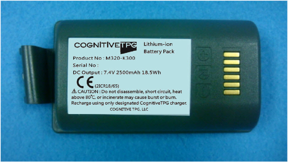
Report No.: 1450507R-RFUSP23V00 Page : 1 of 17 Attachment 2 : EUT Detailed Photographs (1) EUT Photo (2) EUT Photo Report No.: 1450507R-RFUSP23V00 Page : 2 of 17 (3) EUT Photo (4) EUT Photo Report No.: 1450507R-RFUSP23V00 Page : 3 of 17 (5) EUT Photo (6) EUT Photo

ID Label/Location Info

CognitiveTPG, LLC 950 DANBY ROAD ITHACA New York United States 14850 Tel : 607-274-2534 IC Label The IC Label will be placed on the equipment as shown in the photograph below.

Internal Photos

Report No.: 1450507R-RFUSP23V00 Page : 4 of 17 (7) EUT Photo (8) EUT Photo Report No.: 1450507R-RFUSP23V00 Page : 5 of 17 (9) EUT Photo (10) EUT Photo Report No.: 1450507R-RFUSP23V00 Page : 6 of 17 (11) EUT Photo (12) EUT Photo Report No.: 1450507R-RFUSP23V00 Page : 7 of 17 (13) EUT Photo (14) EUT Photo Report No.: 1450507R-RFUSP23V00 Page : 8 of 17 (15) EUT Photo (16) EUT Photo Report No.: 1450507R-RFUSP23V00 Page : 9 of 17 (17) EUT Photo (18) EUT Photo Report No.: 1450507R-RFUSP23V00 Page : 10 of 17 (19) EUT Photo (20) EUT Photo Report No.: 1450507R-RFUSP23V00 Page : 11 of 17 (21) EUT Photo (22) EUT Photo Report No.: 1450507R-RFUSP23V00 Page : 12 of 17 (23) EUT Photo (24) EUT Photo Report No.: 1450507R-RFUSP23V00 Page : 13 of 17 (25) EUT Photo (26) EUT Photo Report No.: 1450507R-RFUSP23V00 Page : 14 of 17 (27) EUT Photo (28) EUT Photo Report No.: 1450507R-RFUSP23V00 Page : 15 of 17 (29) EUT Photo (30) EUT Photo Report No.: 1450507R-RFUSP23V00 Page : 16 of 17 (31) EUT Photo (32) EUT Photo Report No.: 1450507R-RFUSP23V00 Page : 17 of 17 (33) EUT Photo

Test Report

Report No. 1450507R-RFUSP23V00 Page: 1 of 85 FCC Test Report Product Name Bar Code Printer Model No. M320-B010-100 FCC ID. 2ACKK-0481401 Applicant CognitiveTPG, LLC Address 950 DANBY ROAD ITHACA, NY 14850 U.S.A. Date of Receipt Apr. 23, 2012 Issued Date Jun. 13, 2014 Report No. 1450507R-RFUSP23V00 Report Version V1.0 The test results relate only to the samples tested. The test results shown in the test report are traceable to the national/international standard through the calibration report of the equipment and evaluated measurement uncertainty herein. This report must not be used to claim product endorsement by TAF or any agency of the government. The test report shall not be reproduced without the written approval of QuieTek Corporation. Report No. 1450507R-RFUSP23V00 Page: 2 of 85 Test Report Issued Date: Jun. 13, 2014 Report No.: 1450507R-RFUSP23V00 Product Name Bar Code Printer Applicant CognitiveTPG, LLC Address 950 DANBY ROAD ITHACA, NY 14850 U.S.A. Manufacturer CognitiveTPG, LLC Model No. M320-B010-100 FCC ID. 2ACKK-0481401 EUT Rated Voltage DC 7.4V (Power by Battery), DC 12V(Power by Adapter) EUT Test Voltage AC 120V/ 60Hz Trade Name CognitiveTPG Applicable Standard FCC CFR Title 47 Part 15 Subpart C: 2012 ANSI C63.10: 2009 Test Result Complied Documented By : ( Senior Adm. Specialist / Jinn Chen ) Tested By : ( Assistant Engineer / Jack Hsu ) Approved By : ( Director / Vincent Lin ) Report No. 1450507R-RFUSP23V00 Page: 3 of 85 TABLE OF CONTENTS Description Page 1. GENERAL INFORMATION ...............................................................................................................5 1.1. EUT Description......................................................................................................................................5 1.2. Operational Description...........................................................................................................................7 1.3. Tested System Details..............................................................................................................................8 1.4. Configuration of Tested System ..............................................................................................................8 1.5. EUT Exercise Software ...........................................................................................................................9 1.6. Test Facility ...........................................................................................................................................10 2. CONDUCTED EMISSION ................................................................................................................ 11 2.1. Test Equipment ......................................................................................................................................11 2.2. Test Setup ..............................................................................................................................................11 2.3. Limits.....................................................................................................................................................12 2.4. Test Procedure .......................................................................................................................................12 2.5. Uncertainty ............................................................................................................................................12 2.6. Test Result of Conducted Emission .......................................................................................................13 3. PEAK POWER OUTPUT ..................................................................................................................19 3.1. Test Equipment ......................................................................................................................................19 3.2. Test Setup ..............................................................................................................................................19 3.3. Limit .....................................................................................................................................................19 3.4. Test Procedure .......................................................................................................................................19 3.5. Uncertainty ............................................................................................................................................19 3.6. Test Result of Peak Power Output .........................................................................................................20 4. RADIATED EMISSION .....................................................................................................................22 4.1. Test Equipment ......................................................................................................................................22 4.2. Test Setup ..............................................................................................................................................22 4.3. Limits.....................................................................................................................................................23 4.4. Test Procedure .......................................................................................................................................24 4.5. Uncertainty ............................................................................................................................................24 4.6. Test Result of Radiated Emission ..........................................................................................................25 5. RF ANTENNA CONDUCTED TEST................................................................................................39 5.1. Test Equipment ............................................…

Text truncated - open the document above for the full version.

Test Report

Report No. 1450507R-RFUSP23V00 Page: 66 of 85 8. Channel Separation 8.1. Test Equipment Equipment Manufacturer Model No./Serial No. Last Cal. Spectrum Analyzer R&S FSP40 / 100170 Jun, 2013 Spectrum Analyzer Agilent E4407B / US39440758 Jun, 2013 X Spectrum Analyzer Agilent N9010A / MY48030495 Apr., 2014 Note: 1. All equipments are calibrated every one year. 2. The test instruments mark by “X” are used to measure the final test results. 8.2. Test Setup 8.3. Limit Frequency hopping systems shall have hopping channel carrier frequencies separated by a minimum of 25 kHz or the 20 dB bandwidth of the hopping channel, whichever is greater. 8.4. Test Procedure The EUT was setup to ANSI C63.10, 2009; tested to FHSS test procedure of FCC Public Notice DA 00-705 for compliance to FCC 47CFR 15.247 requirements. 8.5. Uncertainty ± 150Hz SMA Connecter EUT Spectrum Analyzer RF Cable Report No. 1450507R-RFUSP23V00 Page: 67 of 85 8.6. Test Result of Channel Separation Limit Limit of (2/3)*20dB Channel No. Frequency (MHz) Measurement Level (kHz) (kHz) Bandwidth (kHz) Result 00 2402 1000 >25 kHz 746.7 Pass 39 2441 1000 >25 kHz 753.3 Pass 78 2480 1000 >25 kHz 753.3 Pass NOTE: The 20dB Bandwidth is refer to section 10. Channel 00 2402MHz Product : Bar Code Printer[u52] Test Item : Channel Separation Test Site : No.3 OATS Test Mode : Mode 1: Transmit - 1Mbps (GFSK) +Adapter#2 Report No. 1450507R-RFUSP23V00 Page: 68 of 85 Channel 39 2441MHz Channel 78 2480 MHz Report No. 1450507R-RFUSP23V00 Page: 69 of 85 Limit Limit of (2/3)*20dB Channel No. Frequency (MHz) Measurement Level (kHz) (kHz) Bandwidth (kHz) Result 00 2402 1000 >25 kHz 920.0 Pass 39 2441 1000 >25 kHz 926.7 Pass 78 2480 1000 >25 kHz 926.7 Pass NOTE: The 20dB Bandwidth is refer to section 10. Channel 00 2402MHz Product : Bar Code Printer[u53] Test Item : Channel Separation Test Site : No.3 OATS Test Mode : Mode 2: Transmit - 3Mbps (8DPSK) +Adapter#2 Report No. 1450507R-RFUSP23V00 Page: 70 of 85 Channel 39 2441MHz Channel 78 2480 MHz Report No. 1450507R-RFUSP23V00 Page: 71 of 85 9. Dwell Time 9.1. Test Equipment Equipment Manufacturer Model No./Serial No. Last Cal. Spectrum Analyzer R&S FSP40 / 100170 Jun, 2013 Spectrum Analyzer Agilent E4407B / US39440758 Jun, 2013 X Spectrum Analyzer Agilent N9010A / MY48030495 Apr., 2014 Note: 1. All equipments are calibrated every one year. 2. The test instruments marked by “X” are used to measure the final test results. 9.2. Test Setup 9.3. Limit The dwell time shall be the average time of occupancy on any frequency shall not be greater than 0.4 seconds within a 30 second period. 9.4. Test Procedure The EUT was setup to ANSI C63.10, 2009; tested to FHSS test procedure of FCC Public Notice DA 00-705 for compliance to FCC 47CFR 15.247 requirements. 9.5. Uncertainty ± 25msec SMA Connecter EUT Spectrum Analyzer RF Cable Report No. 1450507R-RFUSP23V00 Page: 72 of 85 9.6. Test Result of Dwell Time Product : Bar Code Printer[u54] Test Item : Dwell Time Test Site : No.3 OATS Test Mode : Mode 1: Transmit - 1Mbps (GFSK) +Adapter#2 (Channel 00,39,78 –DH5) Frequency (MHz) Time slot length (ms) Hopping of Number Sweep time (ms) Duty cycle Dwell Time (Sec) Limit (Sec) Result 2402 2.900 13 50 0.75 0.302 0.4 Pass 2441 2.900 14 50 0.81 0.325 0.4 Pass 2480 2.890 13 50 0.75 0.301 0.4 Pass Duty cycle =((Time slot length(ms)*Hopping of Number) / Sweep time (ms) Dwell time = (Duty cycle /79) * (79*0.4) CH 00 Time Interval between hops CH 00 Transmission Time CH39 Time Interval between hops CH 39Transmission Time Report No. 1450507R-RFUSP23V00 Page: 73 of 85 CH 78 Time Interval between hops CH 78 Transmission Time Note: The dwell times of the packet type of DH1, DH3, and DH5 are tested. Only the worst case is shown on the report. Report No. 1450507R-RFUSP23V00 Page: 74 of 85 Product : Bar Code Printer[u55] Test Item : Dwell Time Test Site : No.3 OATS Test Mode : Mode 2: Transmit - 3Mbps (8DPSK) +Adapter#2 (Channel 00,39,78 –DH5) Frequency (MHz) Time slot length (ms) Hopping of Number Sweep time (ms) Duty cycle Dwell Time (Sec) Limit (Sec) Result 2402 2.900 13 50 0.75 0.302 0.4 Pass 2441 2.900 13 50 0.75 0.302 0.4 Pass 2480 2.900 13 50 0.75 0.302 0.4 Pass Duty cycle =((Time slot length(ms)*Hopping of Number) / Sweep time (ms) Dwell time = (Duty cycle /79) * (79*0.4) CH 00 Time Interval between hops CH 00 Transmission Time CH39 Time Interval between hops CH 39Transmission Time Report No. 1450507R-RFUSP23V00 Page: 75 of 85 CH 78 Time Interval between hops CH 78 Transmission Time Note: The dwell times of the packet type of DH1, DH3, and DH5 are tested. Only the worst case is shown on the report. Report No. 1450507R-RFUSP23V00 Page: 76 of 85 10. Occupied Bandwidth 10.1. Test Equipment Equipment Manufacturer Model No./Serial No. Last Cal. Spectrum Analyzer R&S FSP40 / 100170 Jun, 2013 Spectrum Analyzer Agilent E4407B / US39440758 Jun, 2013 X Spectrum Analyzer Agilent N9010A / MY48030495 Apr., 2014 Note: 1. All equipments are calibrated every one year. 2. The test instruments marked by “X” are used to measure the final test results. 10.2. Test Setup 10.3. Limits N/A 10.4. Test Procedure The EUT was setup to ANSI C63.10, 2009; tested to FHSS test procedure of FCC Public Notice DA 00-705 for compliance to FCC 47CFR 15.247 requirements. 10.5. Uncertainty ± 150Hz SMA Connecter EUT Spectrum Analyzer RF Cable Report No. 1450507R-RFUSP23V00 Page: 77 of 85 10.6. Test Result of Occupied Bandwidth Product : Bar Code Printer[u56] [u57] Test Item : Occupied Bandwidth Data Test Site : No.3 OATS Test Mode : Mode 1: Transmit - 1Mbps (GFSK) +Adapter#2 (2402MHz) Channel No. Frequency (MHz) Measurement Level (kHz) Required Limit (kHz) Result 00 2402 1120 -- NA Figure Channel 00: Report No. 1450507R-RFUSP23V00 Page: 78 of 85 Product : Bar Code Printer[u58] [u59] Test Item : Occupied Bandwidth Data Test Site : No.3 OATS Test Mode : Mode 1: Transmit - 1Mbps (GFSK) +Adapter#2 (2441MHz) Channel No. Frequency (MHz) Measurement Level (kHz) Required Limit (kHz) Result…

Text truncated - open the document above for the full version.

Test Setup Photos

Report No.: 1450507R-RFUSP23V00 Page : 1 of 4 Attachment 1: EUT Test Setup Photographs Front View of Conducted Test Back View of Conducted Test Report No.: 1450507R-RFUSP23V00 Page : 2 of 4 Front View of Radiated Test Back View of Radiated Test Report No.: 1450507R-RFUSP23V00 Page : 3 of 4 Front View of Radiated Test - (DC Charger) Back View of Radiated Test - (DC Charger) Report No.: 1450507R-RFUSP23V00 Page : 4 of 4 Front View of Radiated Test (Horn) Back View of Radiated Test (Horn)

Contact Information

Applicant

Jeffrey Phoenix(Compliance Engineer)
[email protected]607-274-2534Fax: 607-274-2449

Technical Contact

QuieTek CorporationMaggie Chen
[email protected]886-2-8601-3788

No. 5-22, Rueishu Keng, Linkou Dist., · New Taipei City · Taiwan

Test Firm

DEKRA Testing and Certification Co., Ltd.Sky Hsu
[email protected]886-2-86013788Fax: 886-2-86013789

Technical Specifications

#Rule PartsFrequency RangePower Output
115C2.40 GHz - 2.48 GHz1.20 mW
Confidentiality
Long Term
Grant Notes
Power Output listed is conducted. End-users and installers must be provided with antenna installation instructions and transmitter operating conditions for satisfying RF exposure compliance.

Other Applications from CognitiveTPG, LLC
Bar Code Printer - FCC ID 2ACKK-0481402 - CognitiveTPG, LLC
2ACKK-0481402

Bar Code Printer

Jul 13, 2014

Equipment Class

DTS - Digital Transmission System