2ACLDT2001ARC2310 T2 Contactless Smart Card Terminal
LECIP Arcontia AB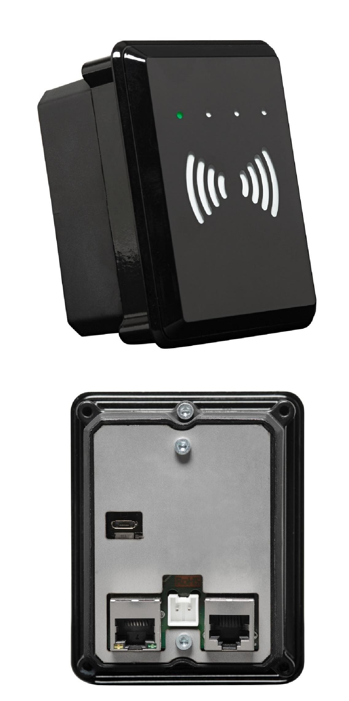
Click to zoom
Application Details
- Equipment Class
- DXX - Part 15 Low Power Communication Device Transmitter
- Date of Grant
- May 05, 2015
- Application Purpose
- Original Equipment
- Date of Application
- May 05, 2015
- Equipment Note
- ARC2310 T2 Contactless Smart Card Terminal
- Frequency Range
- 13.56100000 - 13.56100000
- Company
- LECIP Arcontia AB
- Country
- Sweden
Documents & Files
Document Text
Text extracted from the exhibit documents filed with the FCC. Open a document above to read the original.
Users Manual
Lecip Ar co n t ia AB, Gr u vg at an 35A, 421 30 Väst r a Fr ö lu n d a, Sw ed en , Tel + 46(0)31499930 w w w .ar co n t ia.se su p p o r t @ar co n t ia.se ARC2310 SDK ARC2310/T2 Validator SDK Smart card terminal Technical documentation - Software Development Kit (SDK) ARC2310/T2 SDK v er sio n 1.0 Lecip Ar co n t ia AB, Gr u vg at an 35A, 421 30 Väst r a Fr ö lu n d a, Sw ed en , Tel + 46(0)31499930 w w w .ar co n t ia.se su p p o r t @ar co n t ia.se 2 1 Index 2 Revision history ............................................................................................................................... 3 3 Introduction ..................................................................................................................................... 4 3.1 ARC2310 .................................................................................................................................. 4 3.2 Document version dependencies ............................................................................................ 4 4 ARC2310 System overview .............................................................................................................. 5 4.1 ARC2310 flash layout ............................................................................................................... 5 4.2 ARC2310 File system layout .................................................................................................... 6 4.2.1 Base file system layout .................................................................................................... 6 4.2.2 Layout for /usr/ directory ................................................................................................ 6 5 ARC2310 SSH handling .................................................................................................................... 7 6 Software tools ................................................................................................................................. 8 6.1 Development tool setup for the Arcontia ARC2310................................................................ 8 6.1.1 Tool chain requirements ................................................................................................. 8 6.1.2 Optional software ............................................................................................................ 8 6.1.3 Compiler setup ................................................................................................................ 8 6.2 Restore Image.......................................................................................................................... 8 6.3 Building the sample program ................................................................................................ 10 6.4 Power to the reader .............................................................................................................. 11 7 ARC2310 Linux Devices .................................................................................................................. 12 7.1 Kernel console port ............................................................................................................... 12 7.2 External RS232 port 1 ............................................................................................................ 12 7.3 RFID reader device ................................................................................................................ 12 8 Application development on ARC2310 ......................................................................................... 13 8.1 ARC2310 demo program ....................................................................................................... 13 8.1.1 Building the example ..................................................................................................... 13 8.1.2 Running the example ..................................................................................................... 14 9 Known Issues ................................................................................................................................. 15 ARC2310/T2 SDK v er sio n 1.0 Lecip Ar co n t ia AB, Gr u vg at an 35A, 421 30 Väst r a Fr ö lu n d a, Sw ed en , Tel + 46(0)31499930 w w w .ar co n t ia.se su p p o r t @ar co n t ia.se 3 2 Revision history Release Date Description 1.0 2014-09-09 First dev kit version ARC2310/T2 SDK v er sio n 1.0 Lecip Ar co n t ia AB, Gr u vg at an 35A, 421 30 Väst r a Fr ö lu n d a, Sw ed en , Tel + 46(0)31499930 w w w .ar co n t ia.se su p p o r t @ar co n t ia.se 4 3 Introduction 3.1 ARC2310 T2/ARC2310 3.2 Document version dependencies This document is based on software development kit version 1.0 and the following software and firmware versions. Software or firmware type Version Linux kernel 3.10 ArcB 3.7.15 ARC1300 firmware G ARC2310/T2 SDK v er sio n 1.0 Lecip Ar co n t ia AB, Gr u vg at an 35A, 421 30 Väst r a Fr ö lu n d a, Sw ed en , Tel + 46(0)31499930 w w w .ar co n t ia.se su p p o r t @ar co n t ia.se 5 4 ARC2310 System overview The ARC2310 is GNU/Linux based. The main operating system environment is provided by Busybox v1.20.1 http://www.busybox.net. 4.1 ARC2310 flash layout The flash memory is divided into several partitions for performing secure system upgrades. This table shows the details of these partitions: Partition name Partition size Partition information DTB 2 MiB Device Tree Blob Uboot 8 MiB Boot loader Kernel 8 MiB Kernel partition Root 128 MiB Root partition User 512 MiB User partition ARC2310/T2 SDK v er sio n 1.0 Lecip Ar co n t ia AB, Gr u vg at an 35A, 421 30 Väst r a Fr ö lu n d a, Sw ed en , Tel + 46(0)31499930 w w w .ar co n t ia.se su p p o r t @ar co n t ia.se 6 4.2 ARC2310 File system layout The file system tries to mimic common Posix based systems but there are some specific limitations because of the nature of an embedded Linux system. 4.2.1 Base file system layout The bas…
Text truncated - open the document above for the full version.
Users Manual
ARC2310 T2 e-Ticket Smart Card Reader A rugged and fully integratable compact NFC smart card reader The ARC2310 T2 is a standalone contactless smart card reader designed for use in a variety of payment and ticketing applications, offering faster and more convenient transactions. With its rugged construction and compact size, the T2 can be integrated in almost any sales device, such as vending machines, access control gates, fareboxes, kiosks, parking systems, loyalty schemes and gaming applications. The T2 is housed in a metal case for maximum protection, meeting the demands of any unattended environment. Due to the ferrite-shielded antenna, the T2 can be mounted on all types of material without compromising the reading range or the need to be re-certified or re-tuned. When integrated, the reader measures only 8mm from the terminal’s surface, offering a fully customizable solution. Moreover, it does not compromise the integrity of the IP rating of the host unit. Designed with an ISO/IEC 14443 A/B and NFC contactless smart card reader, the T2 supports a wide range of contactless standards within ticketing and payment, including the entire MIFARE family, Smart MX, FeliCa and Calypso, as well as being EMV contactless extensible. For added flexibility and seamless integration, the T2 comes with an extensive software support package and multiple interfaces, including Ethernet, USB and RS232. Moreover, it comes with an audio buzzer, 4 LED lights and a clearly marked landing zone. With its robust and unique form factor and contactless capabilities, the ARC2310 T2 is the ideal solution for upgrading new and existing payment and ticketing solutions with enhanced contactless features. Areas of use: • Fareboxes • Add Value Machines, Ticket Vending Machines • Turnstile Gates • Vending Machines, Kiosks • Parking Meters • Gas pumps at petrol stations Technical Specification: RF Frequency: 13.56 MHz RF Standards: ISO/IEC 14443 A/B, ISO/IEC 18092 (NFC) RF Speed: 106 kBit/s, 212 kBit/s, 424 kBit/s RF Reading Distance: Up to 50mm (depending on smart card) RF Antenna: Integrated SAM Security: 4 x ISO/IEC 7816 SAM slots with up to 1.1 Mbit/s Crypto Algorithms: 3DES, AES, RSA, PKI Hash Algorithms: SHA1, SHA2, MD5 Processor: i.MX287 working at 450MHz, Flash 4GB eMMC, Linux Kernel 3.1, RAM 128MB Firmware Upgrade: Yes, field upgradeable Interface: RS232, Ethernet 10/100 Mbit/s, USB OTG (On The Go), MicroSD slot User Interface: 4 x Triple coloured LEDs (red/green/yellow), Audio buzzer Power Supply: 9-36V DC Current Consumption: Approx. 4W Dimensions: 100x80x60mm Mounting Hole Required: 95x75mm, front/plate max 6mm thick Weight: Approx. 370g Operating Temperature: -25°C to +50°C Storage Temperature: -30°C to +70°C Compliances: RoHS, FCC, WEEE, CE for bus, tram and rail Supported Smart Cards: MIFARE 1k, MIFARE 4k, MIFARE Plus, MIFARE UltraLight, MIFARE UltraLight C, MIFARE DESFire, MIFARE DESFire EV1, MIFARE SmartMX, GTML, GML2, ISO 14443A tags, ISO 14443B tags, FeliCa RC-S962, FeliCa RC- SA01, Calypso, VDV Supported SAMs: MIFARE SAM (DESFire), MIFARE SAM AV1, MIFARE SAM AV2, S9TSAM, Calypso SAM, FeliCa SAM and other ISO/IEC 7816 compliant SAMs FCC Compliance info: This device complies with part 15 of the FCC Rules. Operation is subject to the following two conditions: (1) This device may not cause harmful interference, and (2) this device must accept any interference received, including interference that may cause undesired operation. Changes or modifications not expressly approved by the party responsible for compliance could void the user's authority to operate the equipment. Note: This equipment has been tested and found to comply with the limits for a Class A digital device, pursuant to part 15 of the FCC Rules. These limits are designed to provide reasonable protection against harmful interference when the equipment is operated in a commercial environment. This equipment generates, uses, and can radiate radio frequency energy and, if not installed and used in accordance with the instruction manual, may cause harmful interference to radio communications. Operation of this equipment in a residential area is likely to cause harmful interference in which case the user will be required to correct the interference at his own expense.
External Photos
ARC2310 T2 Capsulated Unit
ID Label/Location Info
Label Location
ID Label/Location Info
1.5 23 4 (c)(b) (g) (d)(f)(e)(a) (a)~(f)は左揃えのこと バーコード部 22 40 基準は、レベル1〔技標-02001 2-(2)表1〕によること。 2)環境負荷物質非含有のこと。 (g):製造年月 3RD ANGLE PRO. 三 角 法 4 3 2 1 ABC D A BC D 承認 担当 日付 改 訂 副番 K-99664 NAME PLATE(Arcontia) 飯 田 2014. 4.17 2:1 mm 図番 DRWG.No. TITLE MODEL 形式品名 REMARKS 摘 要 MATL. 材 料 SIZE 寸 法 PCS. 個数 UNITS 単位 名 称 DESCRIPTION APPVD.CHKD.DRAWN 製図 検印 承認 SCALE 尺度 NO. 番号 DESIGN 設計 質 量 WEIGHT 3)文書の書体は丸ゴシック体とする。 4)印刷色は、黒色とする。 5)銘板K-99770-*に印刷のこと。 6)(a)~(e)には下記の内容を印刷のこと。 (a):製品名(PRODUCT NAME) (b):型式(MODEL) (c):品番(PART No.) (d):FCC ID (e):定格電圧 (f):シリアルNo.(SERIAL No.) 飯 田 2014. 4.17 注1)この図面はSolidWorksの3Dデータを元に作図されています。 (0.1g) LECIP Confidential
RF Exposure Info
Reference No. 1406200STO-002 www.intertek-etlsemko.com This Statement of Compliance is for the exclusive use of Intertek's client and is provided pursuant to the agreement between Intertek and its Client. Intertek's responsibility and liability are limited to the terms and conditions of the agreement. Intertek assumes no liability to any party, other than to the Client in accordance with the agreement, for any loss, expense or damage occasioned by the use of this Statement. Only the Client is authorized to permit copying or distribution of this Statement of Compliance. Any use of the Intertek name or one of its marks for the sale or advertisement of the tested material, product or service must first be approved in writing by Intertek. 1(1) STATEMENT ON EXPOSURE TO ELECTROMAGNETIC FIELDS EQUIPMENT Type of equipment: 13.56 MHz RFID reader Brand name: Arcontia Type / Model: T2 Manufacturer: Lepic Arcontia AB By request of: Lepic Arcontia AB STANDARD 47 CFR §2.1091, 47 CFR §1.1307, 47 CFR §1.1310, KDB 447498 D01 v05r02 CALCULATIONS Measured field strength from 10 m/distance is 43.3 dBμV/m EIRP is calculated with following formula EIRP = ((E*d)^2)/30 = -41.47 dBm = 7.12*10 -5 mW E = field strength (V/m) d = measurement distance (m) EUT antenna has no gain therefore conducted power is also 7.12*10 -5 mW According to KDB 447498 D01, the 1-g SAR exemption limit for 13.561 MHz and at separation of 5mm is 443 mW. Output power is well below the limit and EUT is exempted from SAR testing. Intertek Semko AB, Radio& EMC Date of issue: 2015-05-05 Issued by: Matti Virkki Intertek Semko AB
Test Report
Test report no. 1406200STO-001 Ed. 1 Page 2 (17) Revision History Edition Date Description 1 2014-06-23 First release Test report no. 1406200STO-001 Ed. 1 Page 3 (17) CONTENTS Page 1 CLIENT INFORMATION .................................................................................................................... 4 2 EQUIPMENT UNDER TEST (EUT) .................................................................................................. 4 2.1 IDENTIFICATION OF THE EUT ACCORDING TO THE MANUFACTURER/CLIENT DECLARATION......... 4 2.2 ADDITIONAL HARDWARE INFORMATION ABOUT THE EUT .............................................................. 5 2.3 ADDITIONAL SOFTWARE INFORMATION ABOUT THE EUT .............................................................. 5 2.4 PERIPHERAL EQUIPMENT ............................................................................................................... 5 2.5 TEST SIGNALS ................................................................................................................................ 5 2.6 MODIFICATION DURING THE TESTS ................................................................................................ 5 3 TEST SPECIFICATIONS ................................................................................................................... 6 3.1 STANDARDS ................................................................................................................................... 6 3.2 ADDITIONS, DEVIATIONS AND EXCLUSIONS FROM STANDARDS AND ACCREDITATION .................. 6 3.3 TEST SITE ....................................................................................................................................... 6 3.4 TEST SET-UP .................................................................................................................................. 7 3.5 TEST CONDITIONS .......................................................................................................................... 7 4 TEST SUMMARY ................................................................................................................................ 8 5 RADIATED TEST BELOW 30 MHZ ................................................................................................. 9 5.1 REQUIREMENT ............................................................................................................................... 9 5.2 TEST SETUP DETAILS ..................................................................................................................... 9 5.3 TEST DATA .....................................................................................................................................11 5.4 TEST EQUIPMENT ..........................................................................................................................12 6 RADIATED EMISSIONS MEASUREMENTS FROM 30 MHZ TO 1000MHZ ...........................13 6.1 REQUIREMENT ..............................................................................................................................13 6.2 TEST SETUP DETAILS ....................................................................................................................13 6.3 TEST DATA .....................................................................................................................................14 6.4 TEST EQUIPMENT ..........................................................................................................................14 7 CARRIER OUTPUT STABILITY MEASUREMENTS ..................................................................15 7.1 REQUIREMENT ..............................................................................................................................15 7.2 TEST SETUP DETAILS ....................................................................................................................15 7.3 TEST DATA .....................................................................................................................................15 7.4 TEST EQUIPMENT ..........................................................................................................................15 8 UNCERTAINTIES SUMMARY .........................................................................................................16 9 PHOTO OF THE EUT ........................................................................................................................17 Test report no. 1406200STO-001 Ed. 1 Page 4 (17) 1 CLIENT INFORMATION The EUT has been tested by request of Company: Lepic Arcontia AB Gruvgatan 35 A 421 30 Västra Frölunda Sweden Name of contact: Tommy Eriksson 2 EQUIPMENT UNDER TEST (EUT) 2.1 Identification of the EUT according to the manufacturer/client declaration Equipment: 13.56 MHz RFID reader Type/Model: T2 Brand name: Arcontia Serial number: No visible serial number on EUT Manufacturer: Lepic Arcontia AB Gruvgatan 35 A 421 30 Västra Frölunda Sweden Transmitter frequency range: 13.561 MHz Receiver frequency range: 13.561 MHz Frequency agile or hopping: Yes No Antenna: Internal antenna External antenna Antenna connector: None, internal antenna Yes, type Type of modulation: No modulation or pulse modulation Temperature range: Category I (General): -20°C to +55°C Category II (Portable equipment): -10°C to +55°C Category III (Equipment for normal indoor use): +5°C to +35°C Other: Transmitter stand by mode supported: Yes No Test report no. 1406200STO-001 Ed. 1 Page 5 (17) 2.2 Additional hardware information about the EUT The EUT consists of the following units: Unit Part number Revision Serial number RFID reader N/A A N/A Following cables were connected to EUT Cable Type Length DC cable 2x0,05 mm 2 with Wϋrth 742 744 426 ferrite 1,5 m Ethernet Cat 5 STP 3 m Serial USB 1 m Serial Cat 5 UTP 1 m 2.3 Additional software information about the EUT During the tests the EUT supported the following software: Software revi…
Text truncated - open the document above for the full version.
Test Setup Photos
1(3) TEST SETUP PHOTOS Radiated test below 30 MHz Radiated test below 30 MHz 2(3) Radiated test below 30 MHz 3(3) Radiated emission 30-1000 MHz Radiated emission 30-1000 MHz
Contact Information
Applicant
Yasuhiro Ohara(Mr)
Technical Contact
LECIP Arcontia ABTommy Eriksson
[email protected]+46 729 870702
Gruvgatan 35A · Vastra Frolunda · Sweden
Non-Technical Contact
LECIP Arcontia ABNiklas Lindhardt
[email protected]+46 729 870703
Test Firm
Intertek Semko ABPar Iggstrom
[email protected]+46708750026
Technical Specifications
| # | Rule Parts | Frequency Range | Power Output |
|---|---|---|---|
| 1 | 15C | 13.561 MHz - 13.561 MHz | - |