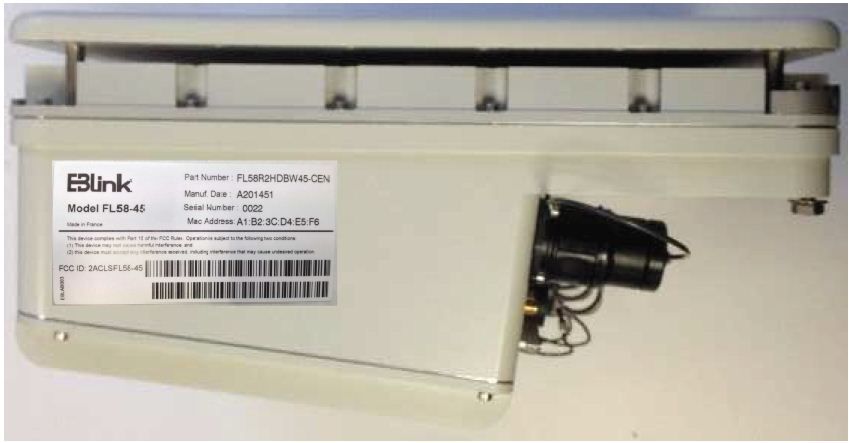
2ACLSFL58-45Wireless Transmitter System
EBlink
Click to zoom
Application Details
- Equipment Class
- NII - Unlicensed National Information Infrastructure TX
- Date of Grant
- May 26, 2015
- Application Purpose
- Original Equipment
- Date of Application
- May 26, 2015
- Equipment Note
- Wireless Transmitter System
- Frequency Range
- 5725.00000000 - 5850.00000000
- Company
- EBlink
- Country
- France (European Territory)
Documents & Files
Document Text
Text extracted from the exhibit documents filed with the FCC. Open a document above to read the original.
Users Manual
1 Document reference – version - date. This material is provided for informational purposes only; EBlink assumes no liability related to its use and expressly disclaims any implied warranties of merchantability or fitness for any particular purpose. All specifications, descriptions, and information contained herein are subject to change without prior notice. © 2014 EBlink Incorporated. ALL RIGHTS RESERVED www.e-blink.com FrontLink™5 8 USER MANUAL Description/Content Document reference: EBOP14-MO185-1 User Manual Version : V5 Date : 2015-05-15 HISTORICAL OF MODIFICATIONS VERSION CHAPTER/PAGE NATURE OF MODIFICATIONS APPLICATION DATE 0.01 ALL CREATION 2013-11-29 0.02 §4 Modification 2015-05-06 This document describes the FL58. 2 Document reference – version - date. This material is provided for informational purposes only; EBlink assumes no liability related to its use and expressly disclaims any implied warranties of merchantability or fitness for any particular purpose. All specifications, descriptions, and information contained herein are subject to change without prior notice. © 2014 EBlink Incorporated. ALL RIGHTS RESERVED www.e-blink.com Table of Contents 1. GENERAL INFORMATION 5 1.1. PURPOSE OF DOCUMENT 5 1.2. SCOPE OF DOCUMENT 5 1.1. RELATED DOCUMENTS 5 2. GENERAL PRODUCT DESCRIPTION 6 2.1. COMPLIANCE WITH THE STANDARD ENVIRONMENTAL CONDITIONS 6 2.2. CE MARKING AND FCC 6 3. PREREQUISITES 8 4. WFM COMPONENT AND DESCRIPTION 9 4.1. LABELLING 12 4.2. EXTERNAL CONNECTORS 12 5. INSTALLING THE SITE 13 5.1. PREPARING THE SITE 13 5.2. PHYSICAL AND ENVIRONMENTAL REQUIREMENTS 13 5.2.1. FL58 WFM CENTRAL & REMOTE LOCATION 13 5.3. UNPACKING THE FL58 13 5.3.1. PACKAGING LIST AND CONTENTS 13 5.3.2. MODULES 14 5.3.3. MOUNTING PREPARATION 14 5.4. PROVIDED BY INSTALLER 14 5.5. REQUIRED KITS 15 5.5.1. POWER CONNECTOR KIT 15 5.5.2. OPTICAL CONNECTOR KIT 15 5.6. MOUNTING PREPARATION 15 5.6.1. PREPARING FOR INSTALLATION 15 5.7. MOUNTING THE FRONTLINK™ 58 ON THE MAST 16 5.8. CONNECTING THE CABLES 16 3 Document reference – version - date. This material is provided for informational purposes only; EBlink assumes no liability related to its use and expressly disclaims any implied warranties of merchantability or fitness for any particular purpose. All specifications, descriptions, and information contained herein are subject to change without prior notice. © 2014 EBlink Incorporated. ALL RIGHTS RESERVED www.e-blink.com 5.8.1. CABLING REQUIREMENTS 16 5.8.2. GENERAL GROUNDING INFORMATION 16 5.8.3. STEPS TO CONNECT THE WEATHERPROOF POWER CORD PLUG 17 5.9. CPRI CONNECTION 19 5.9.1. REQUIRED ITEMS 19 5.9.2. ASSEMBLY STEPS 19 5.10. ALIGNING THE ANTENNA 19 5.10.1. ALIGNMENT/MODEM CONNECTOR 19 5.10.2. OUTPUT ALARMS 19 5.10.3. STATUS LED 20 5.10.4. PERFORMING THE ALIGNMENT 20 5.10.4.1. SETTING THE WFM TO ALIGNMENT MODE AT BOTH END 20 5.10.4.1.1. REPEAT STEPS ABOVE ON THE REMOTE WFM. 21 A. APPENDIX 21 A.1. PACKAGING 21 A.2. HANDLE WITH HOLE DEVICE 22 A.3. ALIGNMENT OPTION 23 A.3.1. DATA VOLT METER CABLE FOR ALIGNMENT (FL58VLTMCBL) 23 A.3.2. ALIGNMENT BUZZER TOOLS (FL58BZZ) 23 A.4. CAPACITY OPTION (FL58ACTIVEPORTBR) 23 A.4.1. CPRI CONNECTION 23 A.4.2. PREREQUISITE 23 A.4.3. REQUIRED ITEMS 24 A.5. ALARM CABLE OPTION (FL58ALCAB217) 24 A.6. TECHNICAL ASSISTANCE 25 A.7. GLOSSARY 25 Warning! Read and follow all warnings notices and instructions marked on the product or included in the documentation. Warning! Only use attachments and accessories specified and/or sold by the manufacturer. 4 Document reference – version - date. This material is provided for informational purposes only; EBlink assumes no liability related to its use and expressly disclaims any implied warranties of merchantability or fitness for any particular purpose. All specifications, descriptions, and information contained herein are subject to change without prior notice. © 2014 EBlink Incorporated. ALL RIGHTS RESERVED www.e-blink.com Warning! Refer all servicing to qualified service personnel. Servicing is required when the device has been damaged in any way, such as power-supply cord or plug is damaged, liquid has been spilled, or objects have fallen into the device, the device has been exposed to rain or moisture, does not operate normally, or has been dropped. Warning! Do not open the chassis. There are no user-serviceable parts inside. Opening the chassis will void the warranty unless performed by an EBlink service center or licensed facility. 5 Document reference – version - date. This material is provided for informational purposes only; EBlink assumes no liability related to its use and expressly disclaims any implied warranties of merchantability or fitness for any particular purpose. All specifications, descriptions, and information contained herein are subject to change without prior notice. © 2014 EBlink Incorporated. ALL RIGHTS RESERVED www.e-blink.com 1. General Information 1.1. Purpose of Document This manual is intended for all installation and service personnel involved in Operation and Maintenance of the FrontLink 58 (FL58) system. This information covered in this manual should be fully understood prior to installation. The FrontLink 58 wireless fronthaul system has been designed for ease of installation and maximum performance. This manual describes the physical installation process recommended for achieving optimal performance. 1.2. Scope Of Document This document is applicable to the FL58-45 and FL58-60 products. The information contained in this document is subject to change without notice. EBlink shall not be liable for errors contained herein or for incidental or consequential damage in connection with the furnishing, performance, or use of this document or equipment supplied with it. Any changes or modifications of equipment not expressly approved by the manufacturer could void the user’s authority to operate the equipment and the warranty for such equipment. 1.1. Related documents This paragraph lists the document related to this …
Text truncated - open the document above for the full version.
Attestation Statements
Software Security Requirements KDB594280 D02-FCC Table of contents REFERENCE DOCUMENTS ................................................................................................................... 1 SOFTWARE SECURITY DESCRIPTION................................................................................................. 2 General Description ...................................................................................................................... 2 Third-Party Access Control .............................................................................................................. 4 USER CONFIGURATION GUIDE ..................................................................................................... 5 REFERENCE DOCUMENTS Ref[1] : FL58 Product Description 1.1 – FCC.pdf Ref[2] : 133826-668754-CEN.pdf and 133826-668754-REM.pdf SOFTWARE SECURITY DESCRIPTION General Description 1. Describe how any software/firmware update will be obtained, downloaded, and installed. Software that is accessed through manufacturer’s website or device’s management system, must describe the different levels of security. It is to be noted that the FL58-45 is not a WIFI device neither a consumer device intended for home nor enterprise usage, but a telecommunication system intended to LTE mobile operators. As such, usage of firmware (FW) on the FL58-45 is fully controlled. As a reminder (please refer to [Ref1]), a FL58-45 system is composed of 2 Hardware units (aka WFM modules) making a wireless fronthaul link between a LTE BBU and RRH. FL58-45 shall only be used for that purpose. The FL58-45 is controlled by a Local Maintenance terminal (sometimes called craft terminal), named “Local and Remote Maintenance Terminal” (LRMT), since it can be used locally to the radio site or remotely from the radio site. The FL58-45 may need new firmware, which would be developed by EBlink. The firmware is not open to external development, i.e. FL58-45 firmware is exclusively developed by EBlink. When a new firmware is available (again produced by EBlink), it is provided to the customers who need it, under a controlled way. Again end customers are necessarily restricted to LTE operators. The firmware is provided by file transfer to the customer, via secured methods agreed with customer. The firmware is uploaded to a FL58-45 via the LRMT. The LRMT connects to a FL58-45 via TCP-IP, and uploads the new FW to a WFM of a FL58-45 link. The firmware can then be forwarded to the other WFM by the 1 st WFM module. Alternatively, the user connects the LRMT to the other WFM module and uploads the new firmware. Multiple checks (checksum, header tag) are performed on the FW file before activation. 2. Describe all the radio frequency parameters that are modified by any software/firmware without any hardware changes. Are these parameters in some way limited, such that, it will not exceed the authorized parameters? Any radio parameters modifiable by firmware are ensured to remain within the authorized limits defined by FCC, as depicted in the test report (Ref[2]). Indeed, the output power is set automatically by the FL58-45, depending on predefined LTE configurations. A predefined LTE configuration is selected by the customer using the LRMT. In any case, the output power is always below the authorized limits set by the FCC. The tests report provides the FL58-45 behaviour with all possible predefined LTE configurations supported by the FL58-45. Finally, the frequency plan might be modified by the customer using the LRMT. The frequency plan can be modified only in the limits of the 5725MHz – 5850MHz frequency band authorized by FCC. The tests report provides the FL58-45 behaviour with all representative possible frequency plans supported by the FL58-45. 3. Describe in detail the authentication protocols that are in place to ensure that the source of the software/firmware is legitimate. Describe in detail how the software is protected against modification. EBlink provides customers with executable firmware only. Source code is kept secret in EBlink. The FL58-45 hardware is proprietary and cannot accommodate standard WIFI software/firmware. No information is published on the HW or EBlink FW, so that it is almost impossible for non-EBlink personnel to develop a firmware for the FL58-45. The firmware is delivered as an encrypted package to customers. The package is protected by a password which is not accessible by customers. The password is only known by the LRMT software, which is provided as executable only. 4. Describe in detail the verification protocols in place to ensure that installed software/firmware is legitimate. The firmware is delivered as an encrypted package to customers. The package is protected by a password which is not accessible by customers. The password is only known by the LRMT software, which is provided as executable only. 5. Describe in detail any encryption methods used to support the use of legitimate software/firmware. Each FW is signed with a specific header tag - kept confidential – containing : - File checksum - Version stamp - File size 6. For a device that can be configured as a master and client (with active or passive scanning), explain how the device ensures compliance for each mode? In particular if the device acts as master in some band of operation and client in another; how is compliance ensured in each band of operation? Not relevant. FL58-45 is not configured in master / client mode as described above, but as a pair of modules to make a radio link. Third-Party Access Control 1. Explain if any third parties have the capability to operate a US sold device on any other regulatory domain, frequencies, or in any manner that is in violation of the certification. EBlink provides customers with executable firmware only. Source code is kept secret in EBlink. The FL58-45 hardware is proprietary and cannot accommodate non-EBlink software/firmware (unlike some WIFI devices). No information is…
Text truncated - open the document above for the full version.
Internal Photos
Antenna Radiator – EBBOARD61 and EBBOARD62/63 without Duplexors EBBOARD62/63 without Carter EBBOARD62/63 with Carter Antenna Radiator – EBBOARD61 and EBBOARD62/63 with Duplexors Daughter Radiator – EBBOARD65 and EBBOARD67
Internal Photos
EBBOARD65 – Pluton 3v2 Board Top EBBOARD65 – Pluton 3v2 Board Bottom EBBOARD62 / 63 – Mars 3v2 Board Top EBBOARD62 / 63 – Mars 3v2 Board Bottom EBBOARD61 – Mercure 3v2 Board Top EBBOARD61 – Mercure 3v2 Board Bottom EBBOARD67 – Mariner Board Top EBBOARD67 – Mariner Board Bottom
RF Exposure Info
FCC Id:2ACLSFL58-45 Prediction of MPE limit at a given distance Equation from page 18 of OET Bulletin 65, Edition 97-01 where:S = power density P = power input to the antenna G = power gain of the antenna in the direction of interest relative to an isotropic radiator R = distance to the center of radiation of the antenna Maximum peak output power at the antenna terminal:19.97(dBm) Maximum peak output power at the antenna terminal:99.31160484(mW) Antenna gain(typical):23(dBi) Maximum antenna gain:199.5262315(numeric) Prediction distance:50(cm) Prediction frequency:5725-5850(MHz) MPE limit for uncontrolled exposure at prediction frequency:1(mW/cm^2) Power density at prediction frequency:0.630740(mW/cm^2) Maximum allowable antenna gain:25.00149873(dBi) This equipment is intended to be used in fixed installations. The minimum distance of 50cm between the product and user is assumed by the way that the equipement is fixed on a pole 2 4R PG S p =
Test Report
This document shall not be reproduced, except in full, without the written approval of the LCIE. This document contains results related only to the item tested. It does not imply the conformity of the whole production to the item tested .Unless otherwise specified; the decision of conformity takes into account the uncertainty of measures. This document does not anticipate any certification decision. TEST REPORT N°: 133829-668754A Subject Radio spectrum Matters (ERM) tests according to standards: 47CFR Part 15.407 Test Site FCC registration number 888863 Issued to EBlink 3 rue marcel Pagnol ZI du Clos Auchin F-91800 Boussy-Saint-Antoine France Apparatus under test Product Front Link (FL58-45) equipment Trade mark EBlink Manufacturer EBlink Model under test FL58R2HDBW45-CEN Serial number 0006 FCC ID 2ACLSFL58-45 Test date March 09th, 2015 to March 23th, 2015 Test location Ecuelles Fontenay Aux Roses Test performed by Laurent Deneux & Arnaud Fayette Composition of document 97 pages Document issued on April 29th, 2015 Written by : Approved by : Arnaud Fayette Stéphane Phoudiah Tests operator Technical manager TEST REPORT N°133829-668754A Page 2/97 SUMMARY 1. TEST PROGRAM ................................................................................................................................ 3 2. EQUIPMENT UNDER TEST: CONFIGURATION (DECLARED BY PROVIDER) ................................ 4 3. MAXIMUM CONDUCTED OUTPUT POWER...................................................................................... 9 4. POWER SPECTRAL DENSITY ......................................................................................................... 12 5. 6DB BANDWIDTH ............................................................................................................................. 27 6. AC POWER LINE CONDUCTED EMISSIONS .................................................................................. 67 7. UNWANTED EMISSIONS ................................................................................................................. 72 8. UNCERTAINTIES CHART ................................................................................................................ 97 TEST REPORT N°133829-668754A Page 3/97 1. TEST PROGRAM References 47 CFR Part 15C ANSI C63.10 Radio requirement: Standard Section Test Description TEST RESULT - Comments CFR 47 § 15.407(a)(3) Maximum Conducted Output Power PASS FAIL NA NP (Limited Program) CFR 47 § 15.407(a)(3) Power Spectral Density PASS FAIL NA NP (Limited Program) CFR 47 § 15.407(b)(4) Undesirable Emission Limits PASS FAIL NA (The EUT complies with peak & average limit of 15.209. See FCC KDB 789033 D02 General UNII Test Procedures New Rules v01 § G 2.C) NP (Limited Program) CFR 47 § 15.407(e) 6dB bandwidth PASS FAIL NA NP (Limited Program) CFR 47 § 15.407(b)(6) CFR 47 § 15.207 AC Power Line Conducted Emissions PASS FAIL NA NP (Limited Program) CFR 47 § 15.407(b)(6) CFR 47 § 15.209 (a) CFR 47 § 15.205 (a) Unwanted Emissions PASS FAIL NA NP (Limited Program) CFR 47 § 15.407(g) Frequency stability PASS (The Manufacturer declares the EUT emission is maintained within the band of operation under all conditions of normal operation as specified in the user manual) FAIL NA NP (Limited Program) This table is a summary of test report, see conclusion of each clause of this test report for detail. PASS: EUT complies with standard’s requirement FAIL: EUT does not comply with standard’s requirement NA: Not Applicable NP: Test Not Performed DP: Declaration of provider TEST REPORT N°133829-668754A Page 4/97 2. EQUIPMENT UNDER TEST: CONFIGURATION (DECLARED BY PROVIDER) 2.1. EQUIPMENT OF THE SAME FAMILY None 2.2. HARDWARE IDENTIFICATION (EUT AND AUXILIARIES): Equipment under test (EUT): FL58R2HDBW45-CEN Serial Number: 0006 Equipment Under Test TEST REPORT N°133829-668754A Page 5/97 Inputs/outputs - Access Type Comments Power supply - - Ethernet - - Optical fiber * 3 - - Auxiliary equipment used during test: Type Reference Sn Comments Laptop CEN - - IQbox Rodhe & scharwz 1409.5504K04 - Optical coupleur Eblink - - Equipment information: Type: Frequency band: 5725MHz-5850MHz Channel bandwidth: 5MHz 10MHz 20MHz Antenna Type: Integral External Dedicated Antenna connector: Yes No Temporary for test Transmit chains: 1 2 Single antenna Symmetrical Asymmetrical Gain 1: 23dBi Gain 2: 23dBi Receiver chains 1 2 Type of equipment: Stand-alone Plug-in Combined Ad-Hoc mode: Yes No Duty cycle: Continuous duty Intermittent duty 100% duty Equipment type: Production model Pre-production model Operating temperature range: Tnom: 20°C Type of power source: AC power supply DC power supply Battery (Select Type) Operating voltage range: Vnom: 207V/50Hz 48Vdc TEST REPORT N°133829-668754A Page 6/97 Channel Plan See “EBDIRTECH15-MEM025-10” EBlink document describing all configurations available for the product. 2.3. RUNNING MODE The EUT is set in the following modes during tests: - Permanent emission with modulation on a fixed channel in the data rate that produced the highest power The specific test software “ETB V1.0.0-LCIE” are used to set the product. Test Configuration Tested Remarks Power limits 1-3-5-7-9-11-13-15-17-19-21-23-25-27- 29-31-32-33-36-38-39-41-42 42 configurations are available on the product. Some configurations are equivalents. So a sampling of the configurations is performed to test the product in Low, Middle, High channel for each bandwidth of the product Power spectral density 1-3-5-7-9-11-13-15-17-19-21-23-25-27- 29-31-32-33-36-38-39-41-42 42 configurations are available on the product. Some configurations are equivalents. So a sampling of the configurations is performed to test the product in Low, Middle, High channel for each bandwidth of the product 6db bandwidth 1-3-5-7-9-11-13-15-17-19-21-23-25-27- 29-31-32-33-36-38-39-41-42 4…
Text truncated - open the document above for the full version.
Test Report
This document shall not be reproduced, except in full, without the written approval of the LCIE. This document contains results related only to the item tested. It does not imply the conformity of the whole production to the item tested .Unless otherwise specified; the decision of conformity takes into account the uncertainty of measures. This document does not anticipate any certification decision. TEST REPORT N°: 133829-668754B Subject Radio spectrum Matters (ERM) tests according to standards: 47CFR Part 15.407 Test Site FCC registration number 888863 Issued to EBlink 3 rue marcel Pagnol ZI du Clos Auchin F-91800 Boussy-Saint-Antoine France Apparatus under test Product Front Link (FL58-45) equipment Trade mark EBlink Manufacturer EBlink Model under test FL58R2HDBW45-REM Serial number 0006 FCC ID 2ACLSFL58-45 Test date March 09th, 2015 to March 23th, 2015 Test location Fontenay Aux Roses Test performed by Laurent Deneux & Arnaud Fayette Composition of document 97 pages Document issued on April 28th, 2015 Written by : Approved by : Arnaud Fayette Stéphane Phoudiah Tests operator Technical manager TEST REPORT N°133829-668754B Page 2/97 SUMMARY 1. TEST PROGRAM ................................................................................................................................ 3 2. EQUIPMENT UNDER TEST: CONFIGURATION (DECLARED BY PROVIDER) ................................ 4 3. MAXIMUM CONDUCTED OUTPUT POWER...................................................................................... 9 4. POWER SPECTRAL DENSITY ......................................................................................................... 12 5. 6DB BANDWIDTH ............................................................................................................................. 27 6. AC POWER LINE CONDUCTED EMISSIONS .................................................................................. 67 7. UNWANTED EMISSIONS ................................................................................................................. 72 8. UNCERTAINTIES CHART ................................................................................................................ 97 TEST REPORT N°133829-668754B Page 3/97 1. TEST PROGRAM References 47 CFR Part 15C ANSI C63.10 Radio requirement: Standard Section Test Description TEST RESULT - Comments CFR 47 § 15.407(a)(3) Maximum Conducted Output Power PASS FAIL NA NP (Limited Program) CFR 47 § 15.407(a)(3) Power Spectral Density PASS FAIL NA NP (Limited Program) CFR 47 § 15.407(b)(4) Undesirable Emission Limits PASS FAIL NA (The EUT complies with peak & average limit of 15.209. See FCC KDB 789033 D02 General UNII Test Procedures New Rules v01 § G 2.C) NP (Limited Program) CFR 47 § 15.407(e) 6dB bandwidth PASS FAIL NA NP (Limited Program) CFR 47 § 15.407(b)(6) CFR 47 § 15.207 AC Power Line Conducted Emissions PASS FAIL NA NP (Limited Program) CFR 47 § 15.407(b)(6) CFR 47 § 15.209 (a) CFR 47 § 15.205 (a) CFR 47 § 15.247 (d) Unwanted Emissions PASS FAIL NA NP (Limited Program) CFR 47 § 15.407(g) Frequency stability PASS (The Manufacturer declares the EUT emission is maintained within the band of operation under all conditions of normal operation as specified in the user manual) FAIL NA NP (Limited Program) This table is a summary of test report, see conclusion of each clause of this test report for detail. PASS: EUT complies with standard’s requirement FAIL: EUT does not comply with standard’s requirement NA: Not Applicable NP: Test Not Performed DP: Declaration of provider TEST REPORT N°133829-668754B Page 4/97 2. EQUIPMENT UNDER TEST: CONFIGURATION (DECLARED BY PROVIDER) 2.1. EQUIPMENT OF THE SAME FAMILY None 2.2. HARDWARE IDENTIFICATION (EUT AND AUXILIARIES): Equipment under test (EUT): FL58R2HDBW45-REM Serial Number: 0006 Equipment Under Test TEST REPORT N°133829-668754B Page 5/97 Inputs/outputs - Cable: Access Type Comments Power supply - - Ethernet - - Optical fiber * 3 - - Auxiliary equipment used during test: Type Reference Sn Comments Laptop CEN - - IQbox Rodhe & scharwz 1409.5504K04 - Optical coupleur Eblink - - Equipment information: Type: Frequency band: 5725MHz-5850MHz Channel bandwidth: 5MHz 10MHz 20MHz Antenna Type: Integral External Dedicated Antenna connector: Yes No Temporary for test Transmit chains: 1 2 Single antenna Symmetrical Asymmetrical Gain 1: 23dBi Gain 2: 23dBi Receiver chains 1 2 Type of equipment: Stand-alone Plug-in Combined Ad-Hoc mode: Yes No Duty cycle: Continuous duty Intermittent duty 100% duty Equipment type: Production model Pre-production model Operating temperature range: Tnom: 20°C Type of power source: AC power supply DC power supply Battery (Select Type) Operating voltage range: Vnom: 207V/50Hz 48Vdc TEST REPORT N°133829-668754B Page 6/97 Channel Plan See “EBDIRTECH15-MEM025-10” EBlink document describing all configurations available for the product. 2.3. RUNNING MODE The EUT is set in the following modes during tests: - Permanent emission with modulation on a fixed channel in the data rate that produced the highest power The specific test software “ETB V1.0.0-LCIE” are used to set the product. Test Configuration Tested Remarks Power limits 1-3-5-7-9-11-13-15-17-19-21-23-25-27- 29-31-32-33-36-38-39-41-42 42 configurations are available on the product. Some configurations are equivalents. So a sampling of the configurations is performed to test the product in Low, Middle, High channel for each bandwidth of the product Power spectral density 1-3-5-7-9-11-13-15-17-19-21-23-25-27- 29-31-32-33-36-38-39-41-42 42 configurations are available on the product. Some configurations are equivalents. So a sampling of the configurations is performed to test the product in Low, Middle, High channel for each bandwidth of the product 6db bandwidth 1-3-5-7-9-11-13-15-17-19-21-23-25-27- 29-31-32-3…
Text truncated - open the document above for the full version.
Test Setup Photos
Test setup photos FCC Id: 2ACLSFL58-45 Test setup for power line conducted emissions Test setup for power line conducted emissions Test setup for radiated field strength Test setup for radiated field strength
Contact Information
Applicant
Michel Geneste(COO)
Test Firm
LCIEPatrick Pereira Teixeira
Technical Specifications
| # | Rule Parts | Frequency Range | Power Output |
|---|---|---|---|
| 1 | 15E | 5.72 GHz - 5.85 GHz | 98.00 mW |