2ACNS-KF01-02key finder
NINGBO JINGHUI OPTO-ELECTRONIC CO., LTD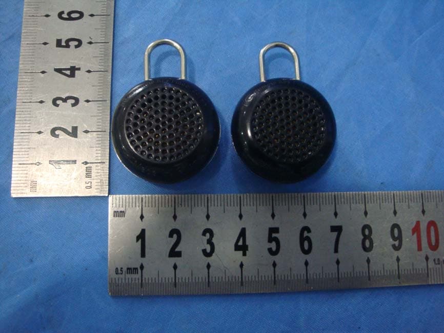
Click to zoom
Application Details
- Equipment Class
- CYY - Communications Receiver used w/Pt 15 Transmitter
- Date of Grant
- Jul 27, 2014
- Application Purpose
- Original Equipment
- Date of Application
- Jul 26, 2014
- Equipment Note
- key finder
- Frequency Range
- 315.00000000 - 315.00000000
- Country
- China
Documents & Files
Document Text
Text extracted from the exhibit documents filed with the FCC. Open a document above to read the original.
Users Manual
Keyfinder receiver Each requires one CR2032 button cell battery (included). NOTE: There are four CR2032 button cell batteries included. Two must be installed prior to your first use and the other two are replacements. Follow these steps for first time installation or if the batteries need to be replaced. 1. Grasp the back cover and screw off counterclockwise. 2. Insert a new battery into the metal slot, ensuring the “+” side of the battery is facing up. The fob will make its characteristic beeping sound as it is inserted into the slot. 3. Replace the back cover by screwing it clockwise back onto the fob. NOTE: Be sure that the "OPEN" markings are facing the bottom as you screw on the cover. This will ensure that the pieces are properly aligned. FCC STATEMENT 1. This device complies with Part 15 of the FCC Rules. Operation is subject to the following two conditions: (1) This device may not cause harmful interference. (2) This device must accept any interference received, including interference that may cause undesired operation. 2. Changes or modifications not expressly approved by the party responsible for compliance could void the user's authority to operate the equipment. NOTE: This equipment has been tested and found to comply with the limits for a Class B digital device, pursuant to Part 15 of the FCC Rules. These limits are designed to provide reasonable protection against harmful interference in a residential installation. This equipment generates uses and can radiate radio frequency energy and, if not installed and used in accordance with the instructions, may cause harmful interference to radio communications. However, there is no guarantee that interference will not occur in a particular installation. If this equipment does cause harmful interference to radio or television reception, which can be determined by turning the equipment off and on, the user is encouraged to try to correct the interference by one or more of the following measures: Reorient or relocate the receiving antenna. Increase the separation between the equipment and receiver. Connect the equipment into an outlet on a circuit different from that to which the receiver is connected. Consult the dealer or an experienced radio/TV technician for help.
External Photos
External photos:
Internal Photos
Internal photos:
Test Report
Report No.: 140609158GZU-002 Issued: 2014-7- 16 FCC ID: 2ACNS-KF01-02 Page 2 of 10 CONTENT TEST REPORT ....................................................................................................................................................................... 1 CONTENT ............................................................................................................................................................................... 2 1 TEST RESULTS SUMMARY ...................................................................................................................................... 3 2 TEST RESULTS CONCLUSION ................................................................................................................................ 4 3 LABORATORY MEASUREMENTS .......................................................................................................................... 5 4 TEST RESULTS ............................................................................................................................................................ 6 4.1 CONDUCTED DISTURBANCE VOLTAGE AT MAINS PORTS .............................................................................................. 6 4.2 RADIATED EMISSION (30 MHZ -2000 MHZ) ................................................................................................................ 6 4.2.1 Used Test Equipment ......................................................................................................................................... 6 4.2.2 Block Diagram of Test Setup ............................................................................................................................. 7 4.2.3 Field Strength Calculation ................................................................................................................................ 7 4.2.4 Test Setup and Procedure .................................................................................................................................. 8 4.2.5 Limit ................................................................................................................................................................... 8 4.2.6 Test Data............................................................................................................................................................ 9 4.2.7 Test Curve ........................................................................................................................................................ 10 4.2.8 Measurement uncertainty ................................................................................................................................ 10 Report No.: 140609158GZU-002 Issued: 2014-7- 16 FCC ID: 2ACNS-KF01-02 Page 3 of 10 1 TEST RESULTS SUMMARY Classification of EUT: Class B Test Item Standard Result Conducted disturbance voltage at mains ports FCC Part 15: 2013, Subpart B N/A Radiated emission (30 MHz–1 GHz) FCC Part 15: 2013, Subpart B Pass Radiated emission (Above 1 GHz) FCC Part 15: 2013, Subpart B Pass Remark: Reference publication is used for methods of measurement: ANSI C63.4:2009 Remark: 1. The symbol “N/A” in above table means Not Applicable. 2. When determining the test results, measurement uncertainty of tests has been considered. Report No.: 140609158GZU-002 Issued: 2014-7- 16 FCC ID: 2ACNS-KF01-02 Page 4 of 10 2 Test Results Conclusion (with Justification) RE: EMC Testing Pursuant to FCC Part 15, Subpart B Performed On the key finder, Model: KF01-02 We tested the key finder, Model: KF01-02, to determine if it was in compliance with the relevant FCC rules as marked on the Test Results Summary. We found that the unit met the requirement of FCC Part 15, Subpart B when tested as received. The worst case’s test data was presented in this test report. The equipment under test (EUT) is controlled by a remote controller; the controller is an intentional radiator using 315MHz frequency. The controller option of this receiver is subject to Certification procedure. The production units are required to conform to the initial sample as received when the units are placed on the market. Report No.: 140609158GZU-002 Issued: 2014-7- 16 FCC ID: 2ACNS-KF01-02 Page 5 of 10 3 LABORATORY MEASUREMENTS Configuration Information Equipment Under Test (EUT): key finder Model: KF01-02 Serial No. Not Labeled Support Equipment: N/A Rated Voltage: DC 3V Condition of Environment: Temperature : 22~28°C Relative Humidity: 35~60% Atmosphere Pressure 86~106kPa Notes: The EMI measurements had been made in the operating mode producing the largest emission in the frequency band being investigated consistent with normal applications. An attempt had been made to maximize the emission by varying the configuration of the EUT. All of the tests are performed at: Shenzhen EMTEK Co., Ltd. Bldg 69,Majialong Industry Zone, Nanshan District, Shen Zhen, Guangdong, 518052 China This test facility and site measurement data have been fully placed on file with the FCC, test firm registration number is 709623. Report No.: 140609158GZU-002 Issued: 2014-7- 16 FCC ID: 2ACNS-KF01-02 Page 6 of 10 4 TEST RESULTS 4.1 Conducted Disturbance Voltage at mains ports Test Result: Not Applicable Remark: This EUT is power by battery 4.2 Radiated Emission (30 MHz -2000 MHz) Test Result: Pass 4.2.1 Used Test Equipment Equipment No. Equipment Model Manufacturer 101414 EMI Test Receiver ESCI R&S 22013 Pre-Amplifier PAP-0203 CD DS1311159163660 Bilog Antenna(30M- 3GHz) VULP9163 Schwarzbeck /DE 531998 RF CABLE 2M 214/U 50 OHM HUBER+SUHNER C37001 RF CABLE 0.5M SS540 HUBER+SUHNER 10051588 RF CABLE 6.5M A05-01-01-6.5M MIcable Inc 414 RF CABLE 1M SAC-40G-1 A.H MY14871/4 RF CABLE 1.5M SUCOFLEX104 HUBER+SUHNER 3# 3m Semi-anechoic Chamber 966 SAEMC 1166.5950K03- 101384Bw EMI Test Receiver ESCI3 Rohde & Schwarz 10051588 RF CABLE 6.5M A05-01-01-6.5M MIcable Inc MY14871/4 RF CABLE 1.5M SUCOFLEX104 HUBER+S…
Text truncated - open the document above for the full version.
Test Setup Photos
FCC ID: 2ACNS‐KF01‐02 Radiated:
Contact Information
Applicant
Gordon Bai(General Manager)
Technical Contact
Intertek Testing Services Shenzhen Ltd.GuangzhouSky Zhu
86-20-82139691
Block E, No.7-2 Guang Dong Software Science Park · GETDD Guangzhou · China
Test Firm
Intertek Testing Services Shenzhen Ltd.strong yao
[email protected]8628219940
Technical Specifications
| # | Rule Parts | Frequency Range | Power Output |
|---|---|---|---|
| 1 | 15B | 315 MHz - 315 MHz | - |
Other Applications from NINGBO JINGHUI OPTO-ELECTRONIC CO., LTD

2ACNS-GTB8R
May 18, 2015LED lamp
Equipment Class
DTS - Digital Transmission System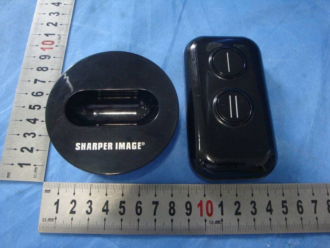
2ACNS-KF01-01
Jul 27, 2014Key finder
Equipment Class
DSC - Part 15 Security/Remote Control Transmitter