2ACP4LBT251BLUETOOTH EARPHONES
Sentry Industries limited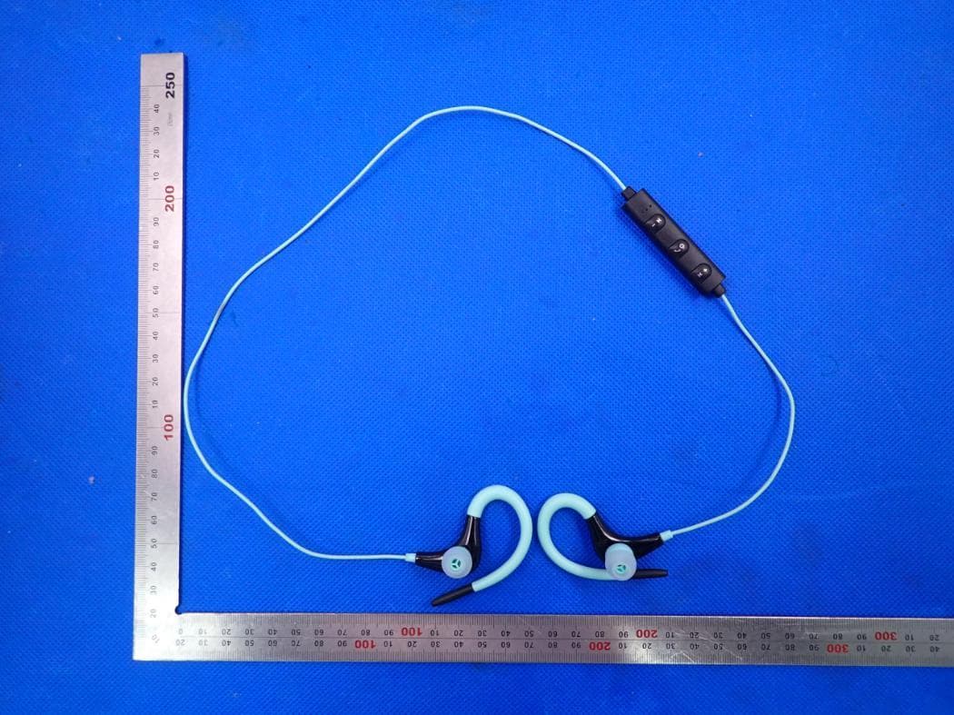
Click to zoom
Application Details
- Equipment Class
- DSS - Part 15 Spread Spectrum Transmitter
- Date of Grant
- Jul 13, 2020
- Application Purpose
- Original Equipment
- Date of Application
- Jul 13, 2020
- Equipment Note
- BLUETOOTH EARPHONES
- Frequency Range
- 2402.00000000 - 2480.00000000
- Company
- Sentry Industries limited
- Country
- China
Documents & Files
Document Text
Text extracted from the exhibit documents filed with the FCC. Open a document above to read the original.
Users Manual
Bluetooth Earbuds with Microphone Before use, make sure battery is fully charged. 1. Find the micro USB slot located on the headphones in-line control 2. Plug Micro USB (small) end into the slot, plug the standard USB (large) end into a charging port or computer. 3. When charging is complete, unplug both ends. The earbuds are ready for use. 1. When pairing, keep the distance between the mobile phone and the headset within 3.5 feet. 2. P ress and hold the button for about 5 seconds, and then release it when the red and blue lights alternately blink. At this time, the headset has entered paring mode. 3. Enable the Bluetooth function of the mobile phone, search the Bluetooth equipment and select After connection is successful, the blue light of the headset will blink slowly. I f the mobile phone prompts to enter the pairing password, please enter and confirm. The pairing mode will be maintained for 5 minutes. If pairing and connection are unsuccessful beyond 2 minutes, the headset will automatically switch to the stand-by mode. After pairing is complete, the headset and the handset will remember each other, without pairing. • • • Sensitivity: 102dB+/-3dB Cord Length: 2ft./0.6M Playtime: Up to 2 hours at 50% volume Frequency: 20Hz-20KHz Battery: Lithium-ion Driver Unit: 10mm Impedance: 32 ohms Version: Bluetooth 5.0 On/Off: Pres s and hold the for 5 seconds to turn on/off. Music Pause: Press the button to pause playing, and press the again to resume playback. Volume Increase: Press and hold the button. Volume Reduction: Press and hold the button. Next Song: Press the button. Previous Song: Press the button. Answer/Hang-up: Press the button to answer when the call is incoming, and press it again to hang up. Rejection: Press and hold the button for about 2 seconds, then release it. Audífonos Intraurales Bluetooth con Micrófono Antes de utilizar, asegúrese de que la batería esté completamente cargada. 1.Localice la ranura del USB micro ubicada en el control en línea de los auriculares 2.Enchufe el extremo (pequeño) del USB micro en la ranura y enchufe el extremo (grande) del USB estándar en un puerto de carga u ordenador. 3.Una vez completada la carga, desenchufe ambos extremos. Los audífonos están listos para ser utilizados. 1.Al emparejarlos, mantenga entre el teléfono móvil y el equipo auricular una distancia de máximo 1 m. 2.Apriete y mantenga apretado el botón de encendido durante unos 5 segundos, y suéltelo cuando las luces rojas y azules parpadeen de modo alternado. En ese momento, el equipo auricular ha pasado al modo de emparejamiento. 3.Habilite la función Bluetooth de su teléfono móvil, busque el equipo Bluetooth y seleccione "." Una vez lograda la conexión, la luz azul de los auriculares parpadeará lentamente. Si el teléfono móvil solicita la introducción de la contraseña de emparejamiento, introduzca "" y confirme. El modo de emparejamiento se mantendrá durante 5 minutos. Si emparejamiento y conexión no se consiguen tras 2 minutos, los auriculares pasarán automáticamente al modo de espera. Una vez completado el emparejamiento, los auriculares y el teléfono móvil se recordarán m utuamente sin emparejarse. • • • Sensibilidad: 102dB+/-3dB Longitud del cable: 0,6M Frecuencia: 20Hz-20KHz Batería:Lithium-ion Unidad de diafragma: 10mm Impedancia: 32 ohms Encendido/Apagado: Apriete y mantenga apretado durante 5 segundos para encender/apagar. Pausar la música: Apriete para pausar la música, y apriete de nuevo para reanudar la reproducción. Aumentar el volumen: Apriete y mantega apretado .Disminuir el volumen: Apriete y mantenga apretado . Canción siguiente: Apriete . Canción anterior: Apriete . Contestar/Colgar: Apriete para contestar cuando entra una llamada, y vuelva a apretarlo para colga r. Rechazar: Apriete y mantenga apretado durante unos 2 segundos, y suéltelo a continuación. •AVISO: Guardar siempre en una ubicación fresca y seca. •AVISO: Los auriculares tienen la capacidad de producir niveles de sonido que pueden dañar su oído. No utilice el volumen alto durante periodos de tiempo prolongados. Los auriculares pueden bloquear los sonidos circundantes. No lleve nunca auriculares mientras conduce un vehículo. Utilícelos con cuidado. El usuario asume todos los riesgos asociados con el uso de este producto. •AVISO: No realice una inserción excesiva en su conducto auditivo. Deje de utilizarlos apenas surja la primera señal de inco modidad. Utilice solo almohadillas diseñadas. No utilice almohadillas sucias o dañadas. Contiene partes pequeñas que pueden suponer peligro de asfixia. Manténgalos alejados de los niños 1.Lea estas instrucciones. 2.Conserve estas instrucciones. 3.Tome nota de todos los avisos. 4.Siga todas las instrucciones. 5.No utilice este aparato cerca del agua. 6.Límpielo sólo con un trapo seco. 7.No obstruya ninguna apertura de ventilación. Utilícelas de acuerdo con las instrucciones del fabr icante. 8.No lo cargue cerca de fuentes de calor tales como radiadores, calefactores, hornos o otros aparatos (incluidos los amplificadores) que produzcan calor. 9.Interrumpa el uso si está dañado. 10.Proteja el cable de manera que nadie o nada lo pise o lo aplaste, particularmente cerca de las clavijas, tomas de corriente y la parte de la salida del aparato. 11.Utilice solo los adjuntos/accesorios especificados por el fabricante. 12.Desenchufe este aparato durante tormentas eléctricas y cuando la carga se haya completado. 13.Toda reparación debe ser realizada p or personal cualificado. Las reparaciones son necesarias cuando el aparato haya sufrido cualquier daño, por ejemplo si está dañado el cable de alimentación o el enchufe, si se ha derramado líquido o si ha habido objetos que han caído dentro del aparato, si el aparato ha sido expuesto a lluvia o humedad, si no funciona con normalidad o si se ha dejado caer. 14.Los auriculares tienen la capacidad de producir niveles de sonido que pueden dañar su oído. No utilice el volumen alto durante periodos de tiempo prolongados. Los auricul…
Text truncated - open the document above for the full version.
Cover Letter(s)
Sentry Industries Limited July 10, 2020 Office of Engineering Technology Federal Communications Commission 7435 Oakland Mills Road Columbia, MD 21046 USA Subject: Explanation of differences between product types FCC ID : 2ACP4LBT251 Model Number: BT237, BT116, BT120, BT135, BT140, BT150, BT175 , BT231, BT234, BT115, BT239, BT250, BT251, BT315, BT320, BT350, BT450, BT550, BT650, BT651, BT652, BT750, BT751, BT752, BT850, BT875, BT885, BT895, BT876, BT877, BT878, BT879, BT886, BT887, BT888, BT889, BX150, BX250 To Whom It May Concern: We, The Sentry Industries Limited hereby declare that the model : BT116, BT120, BT135, BT140, BT150, BT175 , BT231, BT234, BT115, BT239, BT250, BT251, BT315, BT320, BT350, BT450, BT550, BT650, BT651, BT652, BT750, BT751, BT752, BT850, BT875, BT885, BT895, BT876, BT877, BT878, BT879, BT886, BT887, BT888, BT889, BX150, BX250 is identical with the model : BT237, except the model name. Except for the different above, no other modification is performed. Sincerely, Signature: Sentry Industries Limited Contact person: Peetu Melwani
Cover Letter(s)
Sentry Industries Limited Agent Authorization Company: Sentry Industries Limited Address: 507 Houston Center, 63 Mody Road, Tst, Hong Kong, China Product Name: Bluetooth Earphone Model Number(s): BT237, BT116, BT120, BT135, BT140, BT150, BT175 , BT231, BT234, BT115, BT239, BT250, BT251, BT315, BT320, BT350, BT450, BT550, BT650, BT651, BT652, BT750, BT751, BT752, BT850, BT875, BT885, BT895, BT876, BT877, BT878, BT879, BT886, BT887, BT888, BT889, BX150, BX250 Product Description: BLUETOOTH EARPHONES We authorize MiCOM Labs Inc., 575 Boulder Court, Pleasanton, California 94566, USA, to act on our behalf on all matters concerning the certification of above named equipment. We declare that MiCOM Labs Inc. is allowed to forward all information related to the approval and certification of equipment to the regulatory agencies as required and to discuss any issues concerning the approval application. Any and all acts carried out by MiCOM Labs on our behalf shall have the same effect as acts of our own. Signature: Date: 2020-07-10 Name: Peetu Melwani Company: Sentry Industries Limited
Cover Letter(s)
Sentry Industries Limited Office of Engineering Technology Federal Communications Commission 7435 Oakland Mills Road Columbia, MD 21046 USA Date: 2020-07-10 Subject; Request for Confidentiality FCC ID: 2ACP4LBT251 To Whom It May Concern, Pursuant to the provisions of the Commission’s rules Title 47 Sections §0.457 and §0.459, we are requesting the Commission to withhold the following attachment(s) as confidential documents from public disclosure indefinitely. These documents contain detailed system and equipment descriptions and are considered as proprietary information in operation of the equipment. The public disclosure of these documents might be harmful to our company and would give competitors an unfair advantage in the market. Schematic Diagram Block Diagram Parts List Operational Description Tune-up Procedure In additional to above mentioned documents, in order to comply with the marketing regulations in Title 47 CFR §2.803 and the importation rules in Title 47 CFR §2.1204, while ensuring that business sensitive information remains confidential until the actual marketing of newly authorized devices, we request Short Term Confidentiality of the following attachment(s); External Photos Test Setup Photos Internal Photos User Manual For 45 days, pursuant to Public Notice DA 04-1705. OR For 180 days pursuant to KDB 726920 D01. It is our understanding that all measurement test reports, FCC ID label format and correspondence during the certification review process cannot be granted as confidential documents and this information will be available for public review once the grant of equipment authorization is issued. Sincerely Sentry Industries Limited Contact person: Peetu Melwani
External Photos
External Photos TOP VIEW OF EUT BOTTOM VIEW OF EUT FRONT VIEW OF EUT BACK VIEW OF EUT LEFT VIEW OF EUT RIGHT VIEW OF EUT VIEW OF EUT(PORT)
ID Label/Location Info
FCC ID Label Location 5mm*20mm FCC ID: 2ACP4LBT251
Internal Photos
Internal Photos OPEN VIEW OF EUT VIEW OF BATTERY INTERNAL VIEW OF EUT-1 INTERNAL VIEW OF EUT-2 Antenna INTERNAL VIEW OF EUT-3
RF Exposure Info
RF EXPOSURE EVALUATION 1. PRODUCT INFORMATION Product Description BLUETOOTH EARPHONES Model Name BT237 FCC ID 2ACP4LBT251 2. EVALUATION METHOD According to 447498 D01 General RF Exposure Guidance v05 The 1-g and 10-g SAR test exclusion thresholds for 100 MHz to 6 GHz at test separation distances ≤ 50 mm are determined by: [(max. power of channel, including tune-up tolerance, mW)/(min. test separation distance, mm)] ·[√f(GHz)] ≤ 3.0 for 1-g SAR and ≤ 7.5 for 10-g extremity SAR. Where f(GHz) is the RF channel transmit frequency in GHz Power and distance are rounded to the nearest mW and mm before calculation 3. CALCULATION BR/EDR: P t =-8.210dBm=0.15mW The value of the Maximum output power P t is referred to the test report of the CFR47 §15.247. The result for RF exposure evaluation SAR=(0.15mW /5mm) .[√2.402GHz)]=0.05<3.0 for 1-g SAR and ≤ 7.5 for 10-g extremity SAR. 4. CONCLUSION The SAR evaluation is not required.
Test Report
Page 1 of 62 FCC Test Report Report No.: AGC08189200605FE03 FCC ID : 2ACP4LBT251 APPLICATION PURPOSE : Original Equipment PRODUCT DESIGNATION : BLUETOOTH EARPHONES BRAND NAME : SENTRY MODEL NAME : BT237, BT116, BT120, BT135, BT140, BT150, BT175 , BT231, BT234, BT115, BT239, BT250, BT251, BT315, BT320, BT350, BT450, BT550, BT650, BT651, BT652, BT750, BT751, BT752, BT850, BT875, BT885, BT895, BT876, BT877, BT878, BT879, BT886, BT887, BT888, BT889, BX150, BX250 APPLICANT : Sentry Industries Limited DATE OF ISSUE : Jul. 02, 2020 STANDARD(S) : FCC Part 15.247 REPORT VERSION : V1.0 Attestation of Global Compliance (Shenzhen) Co., Ltd CAUTION: This report shall not be reproduced except in full without the written permission of the test laboratory and shall not be quoted out of context. Report No.: AGC08189200605FE03 Page 2 of 62 REPORT REVISE RECORD Report Version Revise Time Issued Date Valid Version Notes V1.0 / Jun. 02, 2020 Valid Initial Release Report No.: AGC08189200605FE03 Page 3 of 62 TABLE OF CONTENTS 1. VERIFICATION OF CONFORMITY ............................................................................................................... 5 2. GENERAL INFORMATION ............................................................................................................................ 6 2.1. PRODUCT DESCRIPTION ..................................................................................................................... 6 2.2. TABLE OF CARRIER FREQUENCYS ..................................................................................................... 6 2.3. RECEIVER INPUT BANDWIDTH ............................................................................................................ 7 2.4. EXAMPLE OF A HOPPING SEQUENCY IN DATA MODE ....................................................................... 7 2.5. EQUALLY AVERAGE USE OF FREQUENCIES AND BEHAVIOUR ........................................................ 7 2.6. RELATED SUBMITTAL(S) / GRANT (S) .................................................................................................. 8 2.7. TEST METHODOLOGY .......................................................................................................................... 8 2.8. SPECIAL ACCESSORIES ....................................................................................................................... 8 2.9. EQUIPMENT MODIFICATIONS .............................................................................................................. 8 3. MEASUREMENT UNCERTAINTY ................................................................................................................. 9 4. DESCRIPTION OF TEST MODES ............................................................................................................... 10 5. SYSTEM TEST CONFIGURATION ............................................................................................................. 11 5.1. CONFIGURATION OF EUT SYSTEM .................................................................................................... 11 5.2 EQUIPMENT USED IN TESTED SYSTEM .............................................................................................. 11 5.3. SUMMARY OF TEST RESULTS ............................................................................................................. 11 6. TEST FACILITY ........................................................................................................................................... 12 7. PEAK OUTPUT POWER ............................................................................................................................. 13 7.1. MEASUREMENT PROCEDURE ........................................................................................................... 13 7.2. TEST SET-UP (BLOCK DIAGRAM OF CONFIGURATION) ................................................................... 13 7.3. LIMITS AND MEASUREMENT RESULT ............................................................................................... 14 8. 20DB BANDWIDTH ..................................................................................................................................... 18 8.1. MEASUREMENT PROCEDURE ........................................................................................................... 18 8.2. TEST SET-UP (BLOCK DIAGRAM OF CONFIGURATION) ................................................................... 18 8.3. LIMITS AND MEASUREMENT RESULTS ............................................................................................. 19 9. CONDUCTED SPURIOUS EMISSION ........................................................................................................ 23 9.1. MEASUREMENT PROCEDURE ........................................................................................................... 23 9.2. TEST SET-UP (BLOCK DIAGRAM OF CONFIGURATION) ................................................................... 23 9.3. MEASUREMENT EQUIPMENT USED .................................................................................................. 23 Report No.: AGC08189200605FE03 Page 4 of 62 9.4. LIMITS AND MEASUREMENT RESULT ............................................................................................... 23 10. RADIATED EMISSION ............................................................................................................................... 34 10.1. MEASUREMENT PROCEDURE ......................................................................................................... 34 10.2. TEST SETUP ....................................................................................................................................... 36 10.3. LIMITS AND MEASUREMENT RESULT ............................................................................................. 37 10.4. TEST RESULT .......................................................…
Text truncated - open the document above for the full version.
Test Report
Report No.: AGC08189200605FE03 Page 44 of 62 EUT BLUETOOTH EARPHONES Model Name BT237 Temperature 25°C Relative Humidity 55.4% Pressure 960hPa Test Voltage Normal Voltage Test Mode Mode 4 Antenna Vertical PK AV RESULT: PASS Report No.: AGC08189200605FE03 Page 45 of 62 EUT BLUETOOTH EARPHONES Model Name BT237 Temperature 25°C Relative Humidity 55.4% Pressure 960hPa Test Voltage Normal Voltage Test Mode Mode 6 Antenna Horizontal PK AV RESULT: PASS Report No.: AGC08189200605FE03 Page 46 of 62 EUT BLUETOOTH EARPHONES Model Name BT237 Temperature 25°C Relative Humidity 55.4% Pressure 960hPa Test Voltage Normal Voltage Test Mode Mode 6 Antenna Vertical PK AV RESULT: PASS Note: The factor had been edited in the “Input Correction” of the Spectrum Analyzer. The π /4-DQPSK modulation is the worst case and recorded in the report. Report No.: AGC08189200605FE03 Page 47 of 62 11. NUMBER OF HOPPING FREQUENCY 11.1. MEASUREMENT PROCEDURE The EUT shall have its hopping function enabled. Use the following spectrum analyzer settings: 1. Span: The frequency band of operation. Depending on the number of channels the device supports, it may be necessary to divide the frequency range of operation across multiple spans, to allow the individual channels to be clearly seen. 2. RBW: To identify clearly the individual channels, set the RBW to less than 30% of the channel spacing or the 20 dB bandwidth, whichever is smaller. 3. VBW ≥ RBW. Sweep: Auto. Detector function: Peak. Trace: Max hold. 4. Allow the trace to stabilize. 11.2. TEST SETUP (BLOCK DIAGRAM OF CONFIGURATION) Same as described in section 8.2 11.3. MEASUREMENT EQUIPMENT USED The same as described in section 6 11.4. LIMITS AND MEASUREMENT RESULT TOTAL NO. OF HOPPING CHANNEL LIMIT (NO. OF CH) MEASUREMENT (NO. OF CH) RESULT >=15 79 PASS TEST PLOT FOR NO. OF TOTAL CHANNELS Note: The GFSK modulation is the worst case and recorded in the report. Report No.: AGC08189200605FE03 Page 48 of 62 12. TIME OF OCCUPANCY (DWELL TIME) 12.1. MEASUREMENT PROCEDURE The EUT shall have its hopping function enabled. Use the following spectrum analyzer settings: 1. Span: Zero span, centered on a hopping channel. 2. RBW shall be≤channel spacing and where possible RBW should be set >> 1 / T, where T is the expected dwell time per channel. 3. Sweep: As necessary to capture the entire dwell time per hopping channel; where possible use a video trigger and trigger delay so that the transmitted signal starts a little to the right of the start of the plot. The trigger level might need slight adjustment to prevent triggering when the system hops on an adjacent channel; a second plot might be needed with a longer sweep time to show two successive hops on a channel. 4. Detector function: Peak. Trace: Max hold. 5. Use the marker-delta function to determine the transmit time per hop. 6. Repeat the measurement using a longer sweep time to determine the number of hops over the period specified in the requirements. The sweep time shall be equal to, or less than, the period specified in the requirements. Determine the number of hops over the sweep time and calculate the total number of hops in the period specified in the requirements, using the following equation: (Number of hops in the period specified in the requirements) = (number of hops on spectrum analyzer) × (period specified in the requirements / analyzer sweep time) 7. The average time of occupancy is calculated from the transmit time per hop multiplied by the number of hops in the period specified in the requirements. 12.2. TEST SETUP (BLOCK DIAGRAM OF CONFIGURATION) Same as described in section 8.2 12.3. MEASUREMENT EQUIPMENT USED The same as described in section 6 12.4. LIMITS AND MEASUREMENT RESULT Channel Time of Pulse for DH5 (ms) Number of hops in the period specified in the requirements Sweep Time (ms) Limit (ms) Low 2.925 24*4 280.800 400 Middle 2.926 27*4 316.008 400 High 2.925 25*4 292.500 400 Note: The π /4-DQPSK modulation is the worst case and recorded in the report. Report No.: AGC08189200605FE03 Page 49 of 62 TEST PLOT OF LOW CHANNEL Report No.: AGC08189200605FE03 Page 50 of 62 TEST PLOT OF MIDDLE CHANNEL Report No.: AGC08189200605FE03 Page 51 of 62 TEST PLOT OF HIGH CHANNEL Report No.: AGC08189200605FE03 Page 52 of 62 13. FREQUENCY SEPARATION 13.1. MEASUREMENT PROCEDURE The EUT shall have its hopping function enabled. Use the following spectrum analyzer settings: 1. Span: Wide enough to capture the peaks of two adjacent channels. 2. RBW: Start with the RBW set to approximately 30% of the channel spacing; adjust as necessary to best identify the center of each individual channel. 3. Video (or average) bandwidth (VBW) ≥ RBW. 4. Sweep: Auto. e) Detector function: Peak. f) Trace: Max hold. g) Allow the trace to stabilize. Use the marker-delta function to determine the separation between the peaks of the adjacent channels. 13.2. TEST SETUP (BLOCK DIAGRAM OF CONFIGURATION) Same as described in section 6.2 13.3. MEASUREMENT EQUIPMENT USED The same as described in section 6.3 13.4. LIMITS AND MEASUREMENT RESULT CHANNEL CHANNEL SEPARATION LIMIT RESULT MHz KHz Pass CH01-CH02 1009 2/3 20 dB BW TEST PLOT FOR FREQUENCY SEPARATION Note: The π /4-DQPSK modulation is the worst case and recorded in the report. Report No.: AGC08189200605FE03 Page 53 of 62 14. FCC LINE CONDUCTED EMISSION TEST 14.1. LIMITS OF LINE CONDUCTED EMISSION TEST Frequency Maximum RF Line Voltage Q.P.( dBuV) Average( dBuV) 150kHz~500kHz 66-56 56-46 500kHz~5MHz 56 46 5MHz~30MHz 60 50 Note: 1. The lower limit shall apply at the transition frequency. 2. The limit decreases linearly with the logarithm of the frequency in the range 0.15 MHz to 0.50 MHz. 14.2. BLOCK DIAGRAM OF LINE CONDUCTED EMISSION TEST EUT & Support Units Report No.: AGC08189200605FE03 Page 54 of 62 14.3. PRELIMINARY PROCEDURE OF LINE CONDUCTED EMISSION TEST 1. The equipment was set up as per the test configuration to simulate typical actual usage per the user’s manual. When the EUT is a tabletop s…
Text truncated - open the document above for the full version.
Test Setup Photos
Test Setup Photos RADIATED EMISSION TEST SETUP BELOW 1GHZ RADIATED EMISSION TEST SETUP ABOVE 1GHZ
Contact Information
Applicant
Peetu Melwani(Manager)
Technical Contact
Test Firm
Attestation of Global Compliance (Shenzhen) Co., LDoris Li
[email protected]+86-755-25234088
Technical Specifications
| # | Rule Parts | Frequency Range | Power Output |
|---|---|---|---|
| 1 | 15C | 2.40 GHz - 2.48 GHz | 200.00 µW |
Other Applications from Sentry Industries limited
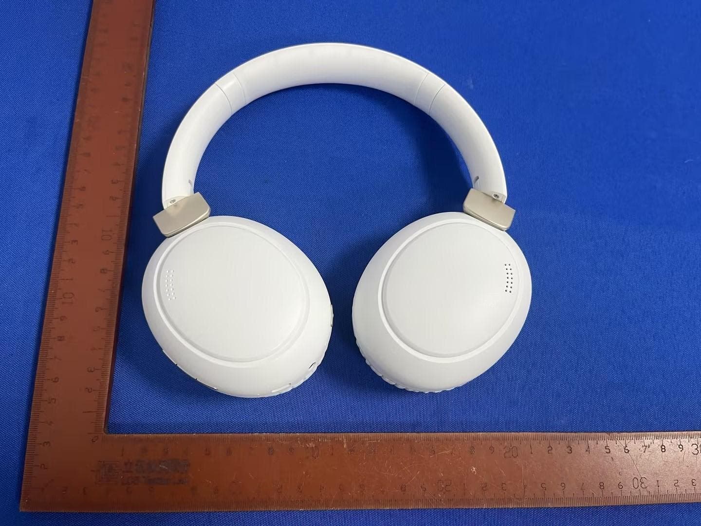
2ACP4BTA2000
Oct 13, 2024Bluetooth Headphone
Equipment Class
DSS - Part 15 Spread Spectrum Transmitter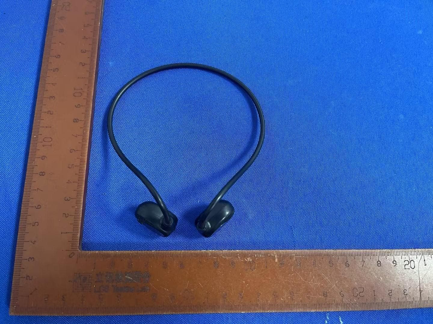
2ACP4BTO100
Oct 13, 2024Bluetooth Earbuds
Equipment Class
DSS - Part 15 Spread Spectrum Transmitter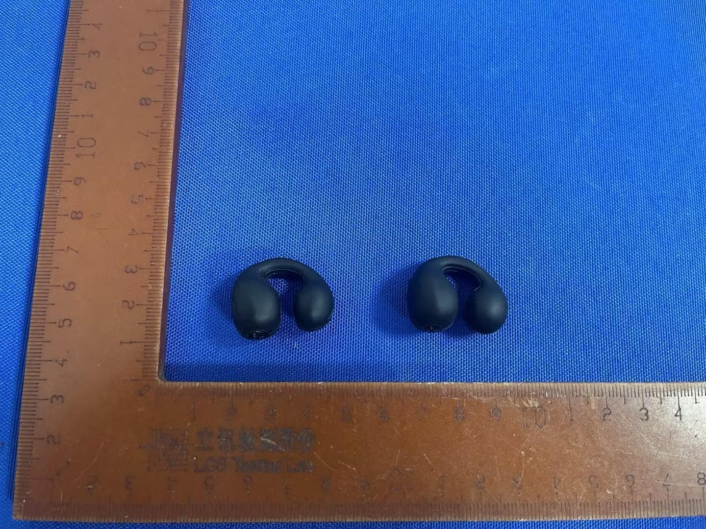
2ACP4BTO200
Oct 13, 2024Bluetooth Earbuds with charging case
Equipment Class
DSS - Part 15 Spread Spectrum Transmitter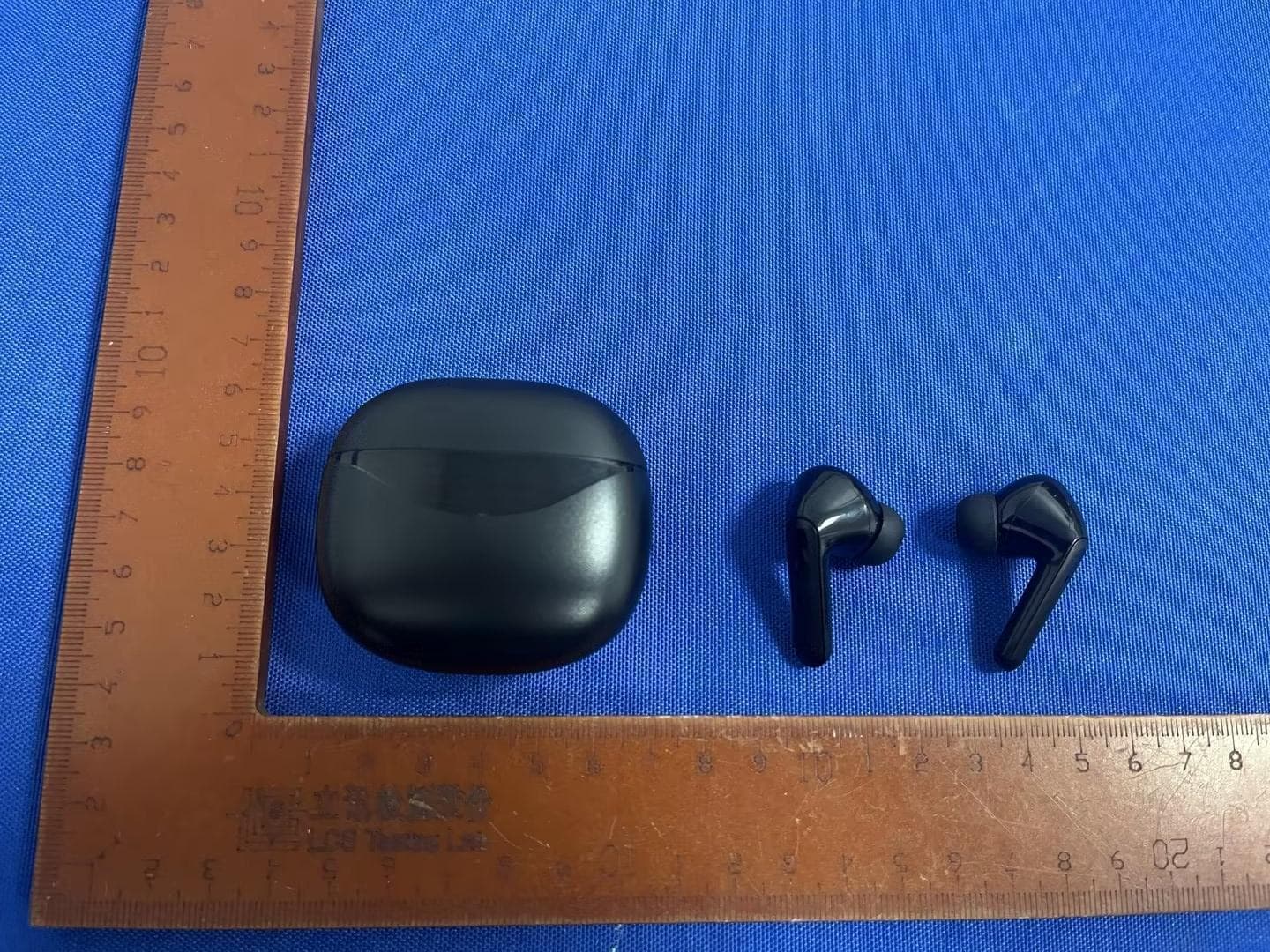
2ACP4BTA255
Oct 13, 2024Bluetooth Earbuds with charging case
Equipment Class
DSS - Part 15 Spread Spectrum Transmitter
2ACP4LBTA200
Aug 11, 2024Bluetooth EARPHONE
Equipment Class
DSS - Part 15 Spread Spectrum Transmitter