2ACQ5SPB411AF01Smart meter
Revogi Innovation Co., Ltd.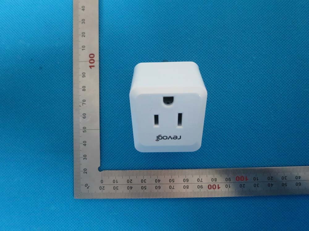
Click to zoom
Application Details
- Equipment Class
- DTS - Digital Transmission System
- Date of Grant
- Nov 15, 2014
- Application Purpose
- Original Equipment
- Date of Application
- Nov 15, 2014
- Equipment Note
- Smart meter
- Frequency Range
- 2402.00000000 - 2480.00000000
- Company
- Revogi Innovation Co., Ltd.
- Country
- China
Documents & Files
Document Text
Text extracted from the exhibit documents filed with the FCC. Open a document above to read the original.
Users Manual
www.revogi.com Add:2018,Anhui Building,No.6007,Shennan Boulevard,Shenzhen,Guangdong,China E:[email protected] T:+86-0755-83595380 Add new devices ® Quick Instruction Guide SPB411 Revogi Innovation Co.,Ltd. Bluetooth Smart Meter Smart meter, connected by Bluetooth 4.0, is kind of smart product which applies the smart phone to control ,e.g the on-off state of electrical appliance and check the power consumption state Description Power meter on work Power meter off work Off On Meter Indicator Function Button Power Touch Button LEDStatus Work as a physical switch to turn the smart meter power on /off Specification 100-120V~ / 60Hz / 10A 2.4GH 37.5X45X24 mm 100-120k V~ / 60Hz / 10A SPB411 Input: Wireless network: System required: Model: Dimention: Output: Weight:50g Android system:more than 800 x480 resolution,Android 2.2+; IOS:iOS6+ Web Browser Request: IE8+,Safari,Firefox,Chrome Installation Download App Scan with phone or pad,click the link,download&install Or search “Revogi” on Google Play and Apple store. Plug the smart meter into outlet Plug the Smart meter into a common power outlet Open the smart phone Bluetooth Products introduction Schedule Add Rule Delete Rule Slide one certain rule to the left/right lightly with the finger and the “Delete” icon will appear, just click it to delete the rule. Timer Click into the timer interface, set the time and start the countdown.. Settings Device Name You can change the name with the device applied like”AC”. Hardware Version Check the device information of the Smart Meter. Factory setting reset Proximity switch Week Click it to show the power consumption history in the past week. Click it to show the power consumption history in the past 30 days. Day Click it to show the power consumption history in the past 24 hours. Month Edit Rule: Click the rule and enter the “Edit Rule” interface. In this interface, you can revise the Time, Name and Rule enabled. It can be realized by clicking“ ” Done ON “ ”Click it to turn off the present power strip/socket. “ ”Click it to turn on the present power strip/socket. Check the watts of the current device powered by smart meter. OFF Watts Energy Meter Click to add rule of the smart meter work time. e.g you can set the rule to require the smart meter work from 6:00 am to 6:00pm. The rule can ben set to work just once or repeatedly. One smart phone can control about 10 smart meters at the same time, so when other new smart meters are applied, please click the on the app start interface and find the new smart meter. When this function start ,the smart meter will automatically start/stopworking as you step into/out the bluetooth coverage. The related dates will be deleted as setting the factory default. Enjoy! Operate the APP Operate the app, the smart meter will automatically liked with the smart phone. Functions Smart Meter interface Click it to show the current total power consumption. The Meter can be One-Key operated by refreshing the data after 5 seconds. Click it to show the curve graph of Daily, Weekly and Monthly power consumption history of each socket. Click it to show the rules which have been set. To set the countdown time for the on-off state Click it to show the version number, the on-off state of RGB LED, Entry Function Control and the factory default setting of the product. Setting Meter Energy Schedulle Timer Touch Button Meter Indicator FCC ID:2ACQ5SPB411AF01 This device complies with part 15 of the FCC rules. Operation is subject to the following two conditions: (1) this device may not cause harmful interference, and (2) this device must accept any interference received, including interference that may cause undesired operation. Changes or modifications to this unit not expressly approved by the party responsible for compliance could void the user's authority to operate the equipment.
External Photos
External Photos TOP VIEW OF EUT BOTTOM VIEW OF EUT FRONT VIEW OF EUT BACK VIEW OF EUT LEFT VIEW OF EUT RIGHT VIEW OF EUT
ID Label/Location Info
FCC ID Label Location FCC ID:2ACQ5SPB411AF01
Internal Photos
Internal Photos OPEN VIEW OF EUT INTERNAL VIEW OF EUT-1 INTERNAL VIEW OF EUT-2 INTERNAL VIEW OF EUT-3 INTERNAL VIEW OF EUT-4 INTERNAL VIEW OF EUT-5 INTERNAL VIEW OF EUT-6 INTERNAL VIEW OF EUT-7 INTERNAL VIEW OF EUT-8 Antenna
Test Report
Page 1 of 52 FCC Test Report Report No.: AGC02200141001FE08 FCC ID : 2ACQ5SPB411AF01 APPLICATION PURPOSE : Original Equipment PRODUCT DESIGNATION : Smart Meter BRAND NAME : Revogi MODEL NAME : SPB411 CLIENT : Revogi Innovation Co., Ltd. DATE OF ISSUE : Nov.11,2014 STANDARD(S) : FCC Part 15 Rules REPORT VERSION : V1.0 Attestation of Global Compliance (Shenzhen) Co., Ltd CAUTION: This report shall not be reproduced except in full without the written permission of the test laboratory and shall not be quoted out of context. Report No.: AGC02200141001FE08 Page 2 of 52 Report Revise Record Report Version Revise Time Issued Date Valid VersionNotes V1.0 / Nov.11,2014 Valid Original Report Report No.: AGC02200141001FE08 Page 3 of 52 TABLE OF CONTENTS 1. VERIFICATION OF COMPLIANCE......................................................................................................... 5 2.GENERAL INFORMATION ...................................................................................................................... 6 2.1PRODUCT DESCRIPTION ............................................................................................................... 6 2.2 RELATED SUBMITTAL(S)/GRANT(S) ............................................................................................. 6 2.3TEST METHODOLOGY .................................................................................................................... 6 2.4 TEST FACILITY ................................................................................................................................ 6 2.5 SPECIAL ACCESSORIES ................................................................................................................ 6 2.6 EQUIPMENT MODIFICATIONS ....................................................................................................... 7 2.7 MEASUREMENT UNCERTAINTY ................................................................................................... 7 3. SYSTEM TEST CONFIGURATION ......................................................................................................... 8 3.1 CONFIGURATION OF TESTED SYSTEM ....................................................................................... 8 3.2 EQUIPMENT USED IN TESTED SYSTEM ...................................................................................... 8 3.3. SUMMARY OF TEST RESULTS ..................................................................................................... 8 4. DESCRIPTION OF TEST MODES .......................................................................................................... 9 5. ANTENNA REQUIREMENT .................................................................................................................... 9 5.1. STANDARD APPLICABLE .............................................................................................................. 9 5.2. TEST RESULT ................................................................................................................................ 9 6. TEST FACILITY ..................................................................................................................................... 10 7. RADIATED EMISSION .......................................................................................................................... 11 7.1 MEASUREMENT PROCEDURE .................................................................................................... 11 7.2 TEST SETUP .................................................................................................................................. 12 7.3 LIMITS AND MEASUREMENT RESULT ........................................................................................ 13 7.4 TEST RESULT (WORST MODULATION: GFSK) ................................................................................ 13 8. BAND EDGE EMISSION ....................................................................................................................... 26 8.1. MEASUREMENT PROCEDURE ................................................................................................... 26 8.2. TEST SET-UP ............................................................................................................................... 26 8.3. TEST RESULT .............................................................................................................................. 27 9. 6DB BANDWIDTH ................................................................................................................................ 31 9.1. TEST PROCEDURE ...................................................................................................................... 31 9.2. SUMMARY OF TEST RESULTS/PLOTS ...................................................................................... 31 10. CONDUCTED OUTPUT POWER ....................................................................................................... 33 10.1. MEASUREMENT PROCEDURE ................................................................................................. 33 10.2. TEST SET-UP (BLOCK DIAGRAM OF CONFIGURATION) ........................................................ 33 10.3. LIMITS AND MEASUREMENT RESULT ..................................................................................... 34 11. MAXIMUM CONDUCTED OUTPUT POWER SPECTRAL DENSITY ................................................ 36 11.1 MEASUREMENT PROCEDURE .................................................................................................. 36 Report No.: AGC02200141001FE08 Page 4 of 52 11.2 TEST SET-UP (BLOCK DIAGRAM OF CONFIGURATION) ......................................................... 36 11.3 LIMITS AND MEASUREMENT RESULT ...................................................................................... 36 12. FCC LINE CONDUCTED EMISSION TEST ..........................................................…
Text truncated - open the document above for the full version.
Test Setup Photos
APPENDIX IV PHOTOGRAPHS OF TEST SETUP FCC LINE CONDUCTED EMISSION TEST SETUP FCC RADIATED EMISSION TEST SETUP
Contact Information
Applicant
Jun Meng(Manager)
Test Firm
Attestation of Global Compliance Shenzhen Co. Ltd.Forrest Lei
Technical Specifications
| # | Rule Parts | Frequency Range | Power Output |
|---|---|---|---|
| 1 | 15C | 2.40 GHz - 2.48 GHz | 100.00 µW |
Other Applications from Revogi Innovation Co., Ltd.
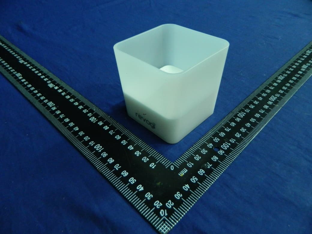
2ACQ5-LTB006
Nov 03, 2015Smart Candle Light
Equipment Class
DTS - Digital Transmission System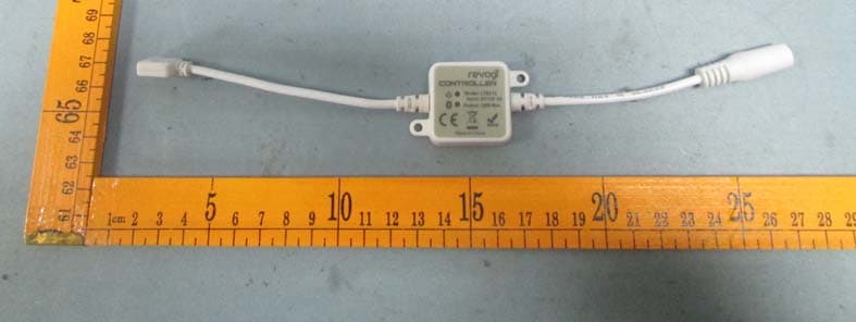
2ACQ5LTB210
Jan 19, 2015Smart LED Strip Controller
Equipment Class
DTS - Digital Transmission System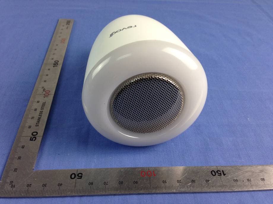
2ACQ5LTW311E06
Jan 04, 2015Melody Light
Equipment Class
DTS - Digital Transmission System2ACQ5LTB211E03
Jul 18, 2014Smart Bulb
Equipment Class
DXX - Part 15 Low Power Communication Device Transmitter