2ACQNAMM002Shoe Electronics
Sigmatek GmbH & Co KG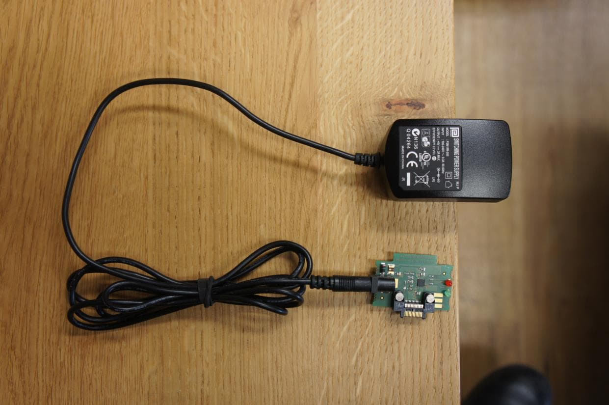
Click to zoom
Application Details
- Equipment Class
- DSS - Part 15 Spread Spectrum Transmitter
- Date of Grant
- May 03, 2015
- Application Purpose
- Original Equipment
- Date of Application
- May 03, 2015
- Equipment Note
- Shoe Electronics
- Frequency Range
- 2402.00000000 - 2480.00000000
- Company
- Sigmatek GmbH & Co KG
- Country
- Austria
Documents & Files
Document Text
Text extracted from the exhibit documents filed with the FCC. Open a document above to read the original.
Users Manual
MS 021 MS Shoe Electronics Date of creation: PRELIMINARY Version date: PRELIMINARY Article number: 21-891-101-E Publisher: SIGMATEK GmbH & Co KG A-5112 Lamprechtshausen Tel.: 06274/4321 Fax: 06274/4321-18 Email: [email protected] WWW.SIGMATEK-AUTOMATION.COM Copyright © 2015 SIGMATEK GmbH & Co KG All rights reserved. No part of this work may be reproduced, edited using an electronic system, duplicated or distrib- uted in any form (print, photocopy, microfilm or in any other process) without the express permission. We reserve the right to make changes in the content without notice. The SIGMATEK GmbH & Co KG is not responsible for technical or printing errors in the handbook and assumes no responsibility for damages that occur through use of this handbook. SHOE ELECTRONICS MS 021 PRELIMINARY Page 1 Shoe Electronics MS 021 This component has: 2-channel evaluation of pressure and speed (with MS 041) control option for vibration motor (on MS 041) monitored control of an ultrasound emitter 2.4 GHz wireless system The ultrasound output is required for the operator positioning (shoe), the sensor evaluation for detecting the triggering pattern and the transmission path for communication with the machine electronics (MS 012). To use the MS 021 module in an application, an MS 012 and Safety CPU module that regu- lates the synchronized communication with the safety modules using safe bus telegrams is also required. This also includes processing the safe application and the distribution of configuration data to remote safety modules. the integrated Li-Ion battery is charged using the MS 052 MS 021 SHOE ELECTRONICS Page 2 PRELIMINARY Contents 1 Basic Safety Guidelines .......................................................... 4 1.1 General Safety Information .......................................................... 4 1.2 Further Safety Guidelines ............................................................ 5 1.3 General Requirements ................................................................. 6 2 Safety Conformity ................................................................... 8 2.1 Functional Safety Standards ....................................................... 8 2.2 Safety-Relevant Parameters ........................................................ 8 3 Delivery Condition ................................................................... 9 4 Installation ............................................................................... 9 5 System Architecture ............................................................. 10 6 Technical Data ....................................................................... 11 6.1 ADXL Interface Specifications ................................................... 11 6.2 FSR Interface Specifications ..................................................... 11 6.3 Vibration Motor Interface Specifications .................................. 12 6.4 Configuration Interface Specifications ..................................... 12 6.5 Electrical Requirements ............................................................. 12 6.5.1 Environmental Conditions ................................................................. 13 6.5.2 Miscellaneous ................................................................................... 13 7 Guidelines for Handling the Battery .................................... 14 SHOE ELECTRONICS MS 021 PRELIMINARY Page 3 8 Safety Guidelines for Handling Li-Ion Batteries *) ............... 15 8.1 Battery Data Sheet ...................................................................... 17 9 Mechanical Dimensions ........................................................ 18 10 Connector Layout .................................................................. 19 11 FCC Statement ....................................................................... 21 MS 021 SHOE ELECTRONICS Page 4 PRELIMINARY 1 Basic Safety Guidelines 1.1 General Safety Information If the safety guidelines are not followed, danger to personnel can arise that could lead to serious injury or in worst cases, death. In less serious cases, systems and equipment can be damaged. The following symbols identify the individual risks as well as the degree of seriousness; their respective meanings are briefly explained. You should therefore familiarize yourself with the safety symbols and their meanings to prevent dangers and risks. DANGER DANGER Identifies an immediate danger with high risk, which can lead to immediate death or serious injury if not avoided. WARNING! WARNING! Identifies a possible danger with a mid-level risk, which can lead to death or (serious) injury if not avoided. CAUTION CAUTION Identifies a low risk danger, which can lead to injury or property damage if not avoided. SHOE ELECTRONICS MS 021 PRELIMINARY Page 5 1.2 Further Safety Guidelines Warning, dangerous electrical voltage Hot surface warning Danger for ESD-sensitive components This symbol identifies important or additional infor- mation regarding the operation of the safety modules. MS 021 SHOE ELECTRONICS Page 6 PRELIMINARY 1.3 General Requirements Technical Documentation This technical documentation is a component of this product. This document must be accessible in the vicinity of the machine, since it contains important instructions. The technical documentation should be included in the sale, rental or transfer of the product. Acceptance of Safety Guidelines Before handling the product to which this documentation be- longs, the operating instructions and safety guidelines must be read. SIGMATEK GmbH & Co KG accepts no liability for damages resulting from non-compliance with the safety guide- lines or the relevant regulations Acceptance of the safety guidelines and the explanations in this document, as well as the Safety System handbook are a basic requirement for proper use. Therefore, read this operating man- ual thoroughly and familiarize yourself with each of them in detail. More information…
Text truncated - open the document above for the full version.
Cover Letter(s)
Ersteller: U. Rodemeier Revision: 04 Erstelldatum: 03.08.01 Datum: 11.05.07 Seite 1 von 1 Request for Confidentiality Federal Communications Commission Date: 2015-03-30 7345 Oakland Mills Road Columbia MD 21046 RE: Certification Application FCC ID: 2ACQNAMM002 Confidentiality Request Pursuant to Sections 0.457 and 0.459 of the Commission’s Rule, the applicant hereby requests confidential treatment of information accompanying this application as outlined below: Block diagram (LTC) Schematics diagram (LTC) Functional description (LTC) Internal Pictures Annex C (STC 180 days) External Pictures Annex B (STC 180 days) Test Setup Picture Annex A (STC 180 days) User manual (STC 180 days) LTC= Long term confidential STC= Short term confidential The above materials contain trade secrets and proprietary information not customarily released to the public. The public disclosure of these matters might be harmful to the applicant and provide unjustified benefits to its competitors. The applicant understands that pursuant to rule 0.457, disclosure of this application and all accompanying documentation will not be made before the date of the GRANT for this application. Thank you for your attention in this matter. Applicant’s Company address: EMV Testhaus GmbH Gustav Hertz Str. 35 94315 Straubing Signature: Job Title and Dept.: Christian Kiermeier
External Photos
EMV TESTHAUS GmbH Gustav-Hertz-Straße 35 94315 Straubing Germany Revision: 1.0 SIGMATEK GmbH & Co KG Shoe Electronics MS021 140603-AU02+W02 Annex B Page 1 of 7 1 Annex B – EUT pictures List of Pictures Picture 1: EUT - exemplary attachment to a safety shoe ................................................... 2 Picture 2: EUT - attached to holder ................................................................................... 2 Picture 3: EUT - view 1 ...................................................................................................... 3 Picture 4: EUT - view 2 ...................................................................................................... 3 Picture 5: EUT (with PCB for activating) ............................................................................ 4 Picture 6: EUT (with PCB for charging) ............................................................................. 4 Picture 7: PCB for activating - top side .............................................................................. 5 Picture 8: PCB for activating - bottom side ........................................................................ 5 Picture 9: switching power supply (with PCB for charging) ................................................ 6 Picture 10: PCB for charging - top side ............................................................................. 6 Picture 11: PCB for charging - bottom side........................................................................ 7 Picture 12: RS232 interface adapter .................................................................................. 7 EMV TESTHAUS GmbH Gustav-Hertz-Straße 35 94315 Straubing Germany Revision: 1.0 SIGMATEK GmbH & Co KG Shoe Electronics MS021 140603-AU02+W02 Annex B Page 2 of 7 Picture 1: EUT - exemplary attachment to a safety shoe Picture 2: EUT - attached to holder EMV TESTHAUS GmbH Gustav-Hertz-Straße 35 94315 Straubing Germany Revision: 1.0 SIGMATEK GmbH & Co KG Shoe Electronics MS021 140603-AU02+W02 Annex B Page 3 of 7 Picture 3: EUT - view 1 Picture 4: EUT - view 2 EMV TESTHAUS GmbH Gustav-Hertz-Straße 35 94315 Straubing Germany Revision: 1.0 SIGMATEK GmbH & Co KG Shoe Electronics MS021 140603-AU02+W02 Annex B Page 4 of 7 Picture 5: EUT (with PCB for activating) Picture 6: EUT (with PCB for charging) EMV TESTHAUS GmbH Gustav-Hertz-Straße 35 94315 Straubing Germany Revision: 1.0 SIGMATEK GmbH & Co KG Shoe Electronics MS021 140603-AU02+W02 Annex B Page 5 of 7 Picture 7: PCB for activating - top side Picture 8: PCB for activating - bottom side EMV TESTHAUS GmbH Gustav-Hertz-Straße 35 94315 Straubing Germany Revision: 1.0 SIGMATEK GmbH & Co KG Shoe Electronics MS021 140603-AU02+W02 Annex B Page 6 of 7 Picture 9: switching power supply (with PCB for charging) Picture 10: PCB for charging - top side EMV TESTHAUS GmbH Gustav-Hertz-Straße 35 94315 Straubing Germany Revision: 1.0 SIGMATEK GmbH & Co KG Shoe Electronics MS021 140603-AU02+W02 Annex B Page 7 of 7 Picture 11: PCB for charging - bottom side Picture 12: RS232 interface adapter
ID Label/Location Info
Lable Location Info
Internal Photos
EMV TESTHAUS GmbH Gustav-Hertz-Straße 35 94315 Straubing Germany Revision: 1.0 SIGMATEK GmbH & Co KG Shoe Electronics MS021 140603-AU02+W02 Annex C Page 1 of 5 1 Annex C – internal pictures 1.1 List of Pictures Picture 1: EUT - open housing ........................................................................................... 2 Picture 2: EUT - without housing, view1 ............................................................................ 2 Picture 2: EUT - without housing, view2 ............................................................................ 3 Picture 3: EUT with onboard-antenna - top side ................................................................ 4 Picture 4: EUT with onboard-antenna - bottom side .......................................................... 4 Picture 5: EUT with antenna-connector - top side ............................................................. 5 Picture 6: EUT with antenna-connector - bottom side ....................................................... 5 EMV TESTHAUS GmbH Gustav-Hertz-Straße 35 94315 Straubing Germany Revision: 1.0 SIGMATEK GmbH & Co KG Shoe Electronics MS021 140603-AU02+W02 Annex C Page 2 of 5 Picture 1: EUT - open housing Picture 2: EUT - without housing, view1 EMV TESTHAUS GmbH Gustav-Hertz-Straße 35 94315 Straubing Germany Revision: 1.0 SIGMATEK GmbH & Co KG Shoe Electronics MS021 140603-AU02+W02 Annex C Page 3 of 5 Picture 3: EUT - without housing, view2 EMV TESTHAUS GmbH Gustav-Hertz-Straße 35 94315 Straubing Germany Revision: 1.0 SIGMATEK GmbH & Co KG Shoe Electronics MS021 140603-AU02+W02 Annex C Page 4 of 5 Picture 4: EUT with onboard-antenna - top side Picture 5: EUT with onboard-antenna - bottom side EMV TESTHAUS GmbH Gustav-Hertz-Straße 35 94315 Straubing Germany Revision: 1.0 SIGMATEK GmbH & Co KG Shoe Electronics MS021 140603-AU02+W02 Annex C Page 5 of 5 Picture 6: EUT with antenna-connector - top side Picture 7: EUT with antenna-connector - bottom side
Test Report
The test result refers exclusively to the tested model. This test report may not be copied or published in a part without the written authorization of the accreditation agency and/or EMV TESTHAUS GmbH Revision: 1.0 Customer: SIGMATEK GmbH & Co KG Obere Donaustr. 57/13 1020 Wien Tel.: +43 1 212 1924-0 Fax: +43 1 212 1924-50 RF test report 140603-AU02+W02 SIGMATEK GmbH & Co KG Shoe Electronics MS021 EMV TESTHAUS GmbH Gustav-Hertz-Straße 35 94315 Straubing Germany Revision: 1.0 SIGMATEK GmbH & Co KG Shoe Electronics MS021 140603-AU02+W02 Page 2 of 83 EMV TESTHAUS GmbH Gustav-Hertz-Straße 35 94315 Straubing Tel.: +49 9421 56868-0 Fax: +49 9421 56868-100 Email: [email protected] Accreditation: FCC facility registration number: 221458 Test Firm Type “2.948 listed”: Valid until 2017-04-22 Test Firm Type “accredited”: Valid until 2015-06-11 MRA US-EU, FCC designation number: DE0010 BnetzA-CAB-02/21-02/04 Valid until 2018-11-27 Industry Canada test site number: 3472A-1 Registration expiry date: 2015-10-02 Test Laboratory: EMV TESTHAUS GmbH Gustav-Hertz-Straße 35 94315 Straubing Germany The technical accuracy is guaranteed through the quality management of the EMV TESTHAUS GmbH EMV TESTHAUS GmbH Gustav-Hertz-Straße 35 94315 Straubing Germany Revision: 1.0 SIGMATEK GmbH & Co KG Shoe Electronics MS021 140603-AU02+W02 Page 3 of 83 Table of contents 1 Test regulations ........................................................................................................................ 7 2 Equipment under Test (EUT) .................................................................................................. 10 3 AC power line conducted emissions ....................................................................................... 12 4 Carrier Frequency Separation................................................................................................. 14 5 Number of Hopping Frequencies ............................................................................................ 17 6 Time of Occupancy (Dwell time) ............................................................................................. 20 7 20 dB bandwidth ..................................................................................................................... 23 8 Occupied bandwidth (99 %) .................................................................................................... 27 9 Maximum conducted output power ......................................................................................... 31 10 Band-edge Compliance .......................................................................................................... 35 11 Spurious RF Conducted Emission .......................................................................................... 40 12 Radiated emission measurement (<1 GHz) ............................................................................ 59 13 Radiated emission measurement (>1 GHz) ............................................................................ 67 14 Equipment calibration status ................................................................................................... 79 15 Measurement uncertainty ....................................................................................................... 81 16 Summary ................................................................................................................................ 82 EMV TESTHAUS GmbH Gustav-Hertz-Straße 35 94315 Straubing Germany Revision: 1.0 SIGMATEK GmbH & Co KG Shoe Electronics MS021 140603-AU02+W02 Page 4 of 83 List of pictures Picture 1: Outline of conducted emission test setup ................................................................. 13 Picture 2: Test setup carrier frequency separation measurement ............................................. 15 Picture 3: Carrier Frequency Separation .................................................................................. 16 Picture 4: Test setup Number of hopping channels measurement ............................................ 18 Picture 5: Number of hopping frequencies - lower part of band ................................................ 19 Picture 6: Number of hopping frequencies - upper part of band ................................................ 19 Picture 7: Test setup time of occupancy measurement............................................................. 21 Picture 8: Signal-on-Time ......................................................................................................... 22 Picture 9: Number of hops within Time of Transmission ........................................................... 22 Picture 10: Test setup for 20dB bandwidth measurement ......................................................... 24 Picture 11: 20dB bandwidth channel 0 ..................................................................................... 25 Picture 12: 20dB bandwidth channel 39 ................................................................................... 25 Picture 13: 20dB bandwidth channel 78 ................................................................................... 26 Picture 14: Test setup for 99 % bandwidth measurement ......................................................... 28 Picture 15: Occupied bandwidth channel 0 ............................................................................... 29 Picture 16: Occupied bandwidth channel 39 ............................................................................. 29 Picture 17: Occupied bandwidth channel 78 ............................................................................. 30 Picture 18: Test setup for conducted output power measurement ............................................ 32 Picture 19: Conducted output power channel 0 ........................................................................ 33 Picture 20: Conducted output power channel 39 ............................................…
Text truncated - open the document above for the full version.
Test Setup Photos
EMV TESTHAUS GmbH Gustav-Hertz-Straße 35 94315 Straubing Germany Revision: 1.0 SIGMATEK GmbH & Co KG Shoe Electronics MS021 140603-AU02+W02 Annex A Page 1 of 6 1 Annex A – Test setup List of Pictures Picture 1: EUT position 1 ................................................................................................... 2 Picture 2: EUT position 2 ................................................................................................... 2 Picture 3: EUT position 3 ................................................................................................... 3 Picture 4: test setup radiated emission test 9 kHz - 30 MHz ............................................. 4 Picture 5: EUT test setup radiated emission test 30 MHz - 1 GHz .................................... 4 Picture 6: EUT test setup in open area test site (front view) .............................................. 5 Picture 7: EUT test setup in open area test site (rear view) ............................................... 5 Picture 8: EUT test setup radiated emissions > 1GHz ....................................................... 6 Picture 9: EUT test setup conducted measurements ......................................................... 6 EMV TESTHAUS GmbH Gustav-Hertz-Straße 35 94315 Straubing Germany Revision: 1.0 SIGMATEK GmbH & Co KG Shoe Electronics MS021 140603-AU02+W02 Annex A Page 2 of 6 Picture 1: EUT position 1 Picture 2: EUT position 2 EMV TESTHAUS GmbH Gustav-Hertz-Straße 35 94315 Straubing Germany Revision: 1.0 SIGMATEK GmbH & Co KG Shoe Electronics MS021 140603-AU02+W02 Annex A Page 3 of 6 Picture 3: EUT position 3 EMV TESTHAUS GmbH Gustav-Hertz-Straße 35 94315 Straubing Germany Revision: 1.0 SIGMATEK GmbH & Co KG Shoe Electronics MS021 140603-AU02+W02 Annex A Page 4 of 6 Picture 4: test setup radiated emission test 9 kHz - 30 MHz Picture 5: EUT test setup radiated emission test 30 MHz - 1 GHz EMV TESTHAUS GmbH Gustav-Hertz-Straße 35 94315 Straubing Germany Revision: 1.0 SIGMATEK GmbH & Co KG Shoe Electronics MS021 140603-AU02+W02 Annex A Page 5 of 6 Picture 6: EUT test setup in open area test site (front view) Picture 7: EUT test setup in open area test site (rear view) EMV TESTHAUS GmbH Gustav-Hertz-Straße 35 94315 Straubing Germany Revision: 1.0 SIGMATEK GmbH & Co KG Shoe Electronics MS021 140603-AU02+W02 Annex A Page 6 of 6 Picture 8: EUT test setup radiated emissions > 1GHz Picture 9: EUT test setup conducted measurements
Contact Information
Applicant
Andreas Stegbuchner
Test Firm
EMV Testhaus GmbHMr. Rainer Heller
Technical Specifications
| # | Rule Parts | Frequency Range | Power Output |
|---|---|---|---|
| 1 | 15C | 2.40 GHz - 2.48 GHz | 60.00 µW |
Other Applications from Sigmatek GmbH & Co KG
2ACQNPHR001
Sep 09, 2014HF-RFID Reader
Equipment Class
DXX - Part 15 Low Power Communication Device Transmitter