FCCID.CO- FCC ID Database
HomeCompaniesEquipment ClassesSearch

© 2026 FCC ID Database. All rights reserved.

AboutContactData sourced from FCC public records
  1. Home/
  2. HENES CO.,LTD./
  3. 2ACR2-HRC-U14

2ACR2-HRC-U14Wireless Remote Controller

HENES CO.,LTD.
Wireless Remote Controller - FCC ID 2ACR2-HRC-U14 - HENES CO.,LTD.
Click to zoom

Application Details

Equipment Class
DSS - Part 15 Spread Spectrum Transmitter
Date of Grant
Aug 26, 2014
Application Purpose
Original Equipment
Date of Application
Aug 26, 2014
Equipment Note
Wireless Remote Controller
Frequency Range
2402.00000000 - 2480.00000000
Company
HENES CO.,LTD.
Country
South Korea

Documents & Files

Select a file to view
Users Manual

↗

Cover Letter(s)

↗
↗
↗
↗

External Photos

↗

ID Label/Location Info

↗

Internal Photos

↗

RF Exposure Info

↗

Test Report

↗

Test Setup Photos

↗

Document Text

Text extracted from the exhibit documents filed with the FCC. Open a document above to read the original.

Users Manual

Wireless Remote Control/Receiver Manual (HRC-U14-01/HRC-V14-01) HENES Co.,Ltd 2014-08-20 Update Revision 0.3  Introduction Package Contents Wireless Remote Control Receiver (in BROON) AAA Battery(2 Piece) User Manual Product Specification Classification Contents Model Name HRC-U14-01/HRC-V14-01 Power 3V DC Frequency 2.4GHz Buttons Power Switch Handle Gearshift Lever Emergency Stop Button Unpair & Calibration key 사용설명서  Product Overview ① LED : Show the current state of the remote control. Reference ‘Indicator LED’ ② Power Switch : Power ON of OFF the Remote Control. ③ Handle : ⑤ Emergency Stop Button ④ Gearshift Lever ③ Handle ② Power Switch ① LED ⑥ Unpair & Calibration key Turn Right Turn Left ⑦ Download Port ④ Gearshift Lever ⑤ Emergency Stop Button : One push this button, Car stops running. Push button one more, car running again. ⑥ Unpair & Calibration key : Use Unpair & Calibration. ⑦ Download Port : Use to Download FW for Remote Control. Forward Backward  Assembly 1. Insert the battery by opening the battery cover. 2. Change to ON the power button on the bottom front. 3. The green LED flashes, it is a normal condition. However, if the power supply of the vehicle is OFF, the orange LED flashes.  How to Use RCU Manual • Pair Sequence (Unpair to Pair) - RCU 1. Push Stop Key. (Push the Stop key if Not complete Pair, Stop the Pair Sequence.) • Unpair Sequence (Pair to Unpair) - RCU 1. Push Unpair & Calibration Key about 5 sec when boot time. • Emergency Stop Sequence (When Pair state) - RCU 1. Push Stop key: Running Mode <---> Emergency Stop Mode Toggled. 2. When Emergency Stop state, car can’t use run and handle. • Driver lever - RCU 1. Forward : Pull the Gearshift lever to forward. (20-degree Angle) 2. Backward : Push the Gearshift lever to backward. (10-degree Angle) • Wheel lever - RCU 1. Turn Right : Pull handle right. (30-degree Angle) 2. Turn Left : Pull handle left. (30-degree Angle) • Calibration - RCU 1. Push the Unpair & Calibration Key. (Change the potentiometer of drive/handle) • Vibration (Pair State) - RCU 1. Vibrate motor when RSSI is low. 2. Stop vibrate when RSSI is high. • Indicator LED - RCU 1. Pair : Green LED flashes (1.0 second) ■ 2. Unpair : Red LED flashes (0.1 second) ■ 3. Disconnect : Orange LED flashes (1.0 second) ■ 4. Emergency Stop : Orange LED flashes (0.1 second) ■ 5. Low Battery : Red LED flashes (0.1 second) ■ RCV Manual • Pair Sequence (Unpair to Pair) - RCV 1. Push the Stop Key. (Push the Stop key if Not complete Pair, Stop the Pair Sequence.) • Unpair Sequence (Pair state) - RCV 1. Push the Unpair & Calibration Key. • Indicator LED - RCV 1. Pair : Green LED flashes (1.0 second) ■ 2. Unpair : Red LED flashes (0.1 second) ■ 3. Disconnect : Orange LED flashes (1.0 second) ■  Caution Any changes or modifications in construction of this device which are not expressly approved by the party responsible for compliance could void the user's authority to operate the equipment. Risk of explosion if battery is replaced by an incorrect type. Dispose of used batteries according to the instructions. This equipment may generate or use radio frequency energy. Changes or modifications to this equipment may cause harmful interference unless the modifications are expressly approved in the instruction manual. The user could lose the authority to operate this equipment if an unauthorized change or modification is made. Note: This equipment has been tested and found to comply with the limit for a Class B digital device, pursuant to part 15 of the FCC Rules. These limits are designed to provide reasonable protection against harmful interference in a residential installation. This equipment generates, uses and can radiate radio frequency energy and, if not installed and used in accordance with the instructions, may cause harmful interference to radio communications, However, there is no guarantee that interference will not occur in a particular installation. If this equipment does cause harmful interference to radio or television reception, which can be determined by turning the equipment off and on, the user is encouraged to try to correct the interference by one or more of the following measures —Reorient or relocate the receiving antenna. —Increase the separation between the equipment and receiver. —Connect the equipment into an outlet on a circuit different from that to which the receiver is connected. —Consult the dealer or an experienced radio/TV technician for help.

Cover Letter(s)

HENES CO.,LTD. 52, Hamansandan 3-gil, Gunbuk-myeon, Haman-gun, Gyeongsangnam-do, Korea 637-821 August 19, 2014 Attestation Letter for FCCID: 2ACR2-HRC-U14 We declare, the Max duty is 0.1% for this device (Model Name : HRC-U14-01). Sincerely, Yeon-soo, Park Staff

Cover Letter(s)

HENES CO.,LTD. 52, Hamansandan 3-gil, Gunbuk-myeon, Haman-gun, Gyeongsangnam-do, Korea 637-821 Date: August 19, 2014 Letter of Authorization We, the undersigned, hereby authorize Harvey Sung of Digital EMC Co., Ltd. to act on our behalf in all manners relating to application for equipment authorization for FCCID: 2ACR2-HRC-U14 including signing of all documents relating to these matters. Any and all acts carried out by Harvey Sung of DT&C Co., Ltd. on our behalf shall have the same affect as acts of our own. This authorization is valid until further written notice from HENES CO.,LTD. . “I, the undersigned, hereby certify that we are not subject to a denial of federal benefits, that includes FCC benefits, pursuant to Section 5301 of the Anti-Drug Abuse Act of 1988, 21 U.S.C. 853(a).” Sincerely, Yeon-soo, Park Staff

Cover Letter(s)

DT&C Co., Ltd. 42, Yurim-ro, 154beon-gil, Cheoin-gu, Yongin-si, Gyeonggi-do, Korea 449-935 Date: August 19, 2014 UL Verification Services Inc. 47173 Benicia Street Fremont, CA 94538, USA To whom it may concern: I, the undersigned, hereby authorize Ms. Claire Hoque/Application Examiner of Compliance Engineering Services, Inc., d.b.a. Compliance Certification Services and hereafter referred to as CCS, to act on our behalf in all manners relating to application for equipment authorization, including signing of all documents relating to these matters. Any and all acts carried out by Ms. Claire Hoque of CCS on our behalf shall have the same effect as acts of our own. I, the undersigned, hereby certify that we are not subject to a denial of federal benefits, that includes FCC benefits, pursuant to Section 5301 of the Anti-Drug Abuse Act of 1988, 21 U.S.C. 853(a). In authorizing CCS as our agent, we still recognize that we are responsible to: a) comply with the relevant provisions of the certification program; b) make all necessary arrangements for the conduct of the evaluation, including provision for examining documentation and access to all areas, records (including internal audit reports) and personnel for the purposes of evaluation (e.g. testing, inspection, assessment, surveillance, reassessment) and resolution of complaints; c) make claims regarding certification only in respect of the scope for which certification has been granted; d) do not use our product certification in such a manner as to bring the Certification Division into disrepute and not make any statement regarding our product certification which the Certification Division may consider misleading or unauthorized; e) upon suspension or cancellation of certification, discontinue use of all advertising matter that contains any reference thereto and return any certification documents as required by the Certification Division; f) use certification only to indicate the products are certified as being in conformity with specified standards;

Cover Letter(s)

HENES CO.,LTD. 52, Hamansandan 3-gil, Gunbuk-myeon, Haman-gun, Gyeongsangnam-do, Korea 637-821 Date: August 19, 2014 UL Verification Services Inc. 47173 Benicia Street Fremont, CA 94538, USA RE: Request of Confidentiality for FCCID: 2ACR2-HRC-U14 To Whom It may Concern: Pursuant to Sections 0.457 and 0.459 of the Commission`s Rules(CFR 47), and Section 552 (b) (4) of the Freedom of Information Act, HENES CO.,LTD. hereby requests confidentiality and treatment of certain information accompanying this application. The materials contain trade secrets and proprietary information not customarily released to the public. The public disclosure of these matters might be harmful to the Applicant and provide unjustified benefits to its competitors. We are also hereby request Short-Term Confidentiality for 180 days after the grant as outlined in Public Notice DA 04-1705. This provision will give HENES CO.,LTD. temporary confidentiality of commercially sensitive information prior to product release. The requested permanent and Short-Term Confidential exhibits are listed as follows: PERMANENT & SHORT-TERM CONFIDENTIAL LIST Exhibit Description PERMANENT 1 Block Diagram 2 Schematics 3 Part Lists 4 Operation Description SHORT-TERM 5 Internal Photos 6 External Photos 7 Test-Setup Photos 8 User Manual The Applicant understands that pursuant to Rule 0.457, disclosure of this application and all accompanying documentations, where applicable, will not be public before the date of the Grant for this application. Sincerely, Yeon-soo, Park Staff

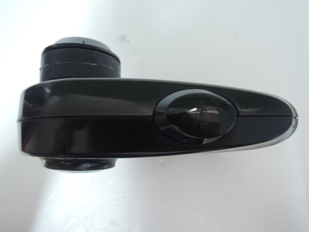
External Photos

FCC ID: 2ACR2-HRC-U14 Copyright Ⓒ 2014, DT&C Co., Ltd. View 1 FCC ID: 2ACR2-HRC-U14 Copyright Ⓒ 2014, DT&C Co., Ltd. View 2 FCC ID: 2ACR2-HRC-U14 Copyright Ⓒ 2014, DT&C Co., Ltd. View 3

ID Label/Location Info

FCC ID: 2ACR2-HRC-U14 Copyright Ⓒ 2014, DT&C Co., Ltd. FCC ID SAMPLE LABEL & LOCATION LABELLING REQUIREMENTS PER §2.925 The Label shown shall be permanently affixed at a conspicuous location on the device and be readily visible to the user at the time of purchase - The FCC label shown is representative of the label that will appear on the radio when in production. Other information may also be included on this label. - The device is so small that it is not practicable to place the statement specified under 15.19 statement request, the information required by this paragraph shall be placed in a prominent location in the user's manual.

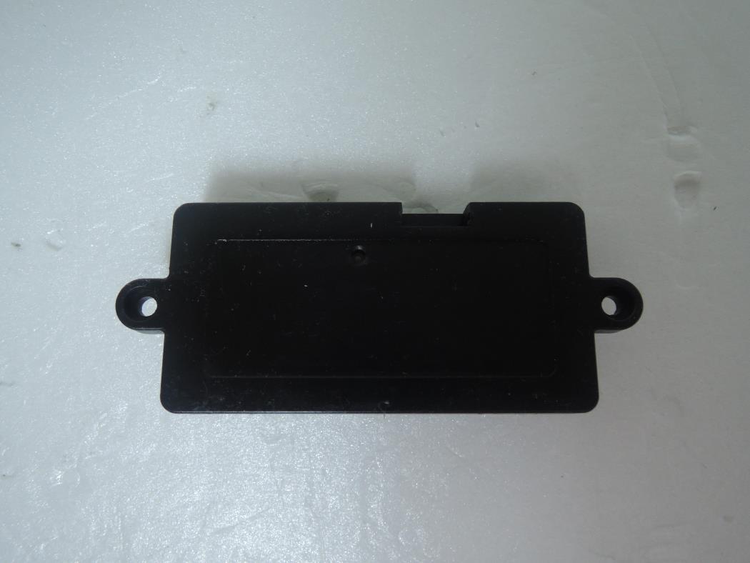
Internal Photos

FCC ID: 2ACR2-HRC-U14 Copyright Ⓒ 2014, DT&C Co., Ltd. View 1 FCC ID: 2ACR2-HRC-U14 Copyright Ⓒ 2014, DT&C Co., Ltd. View 2 FCC ID: 2ACR2-HRC-U14 Copyright Ⓒ 2014, DT&C Co., Ltd. View 3 FCC ID: 2ACR2-HRC-U14 Copyright Ⓒ 2014, DT&C Co., Ltd. View 4 Antenna

RF Exposure Info

MHzmm = Typical Power: ± = [ / ] * [ √ ] 5 2480 - Min. test separation distance = mW 0.83 1.00 dBm - Min. transmitting frequency = dB 0.00 dBm 1.00 dBm Measured Output Power: 2ACR2-HRC-U14 200 248 5 - Max. power with turn-up tolerance = 2 Used Step 1) SAR test exclusion thresholds for 100MHz to 6GHz at te st separationn distances ≤ 50 mm = [(max. power of channel, including tune-up tolerance, mW)/(min. test separation distance, mm)] · [√f(GHz)] FCC ID : Standalone SAR test exclusion considerations August 19, 2014 = [ / ] [ √ ] = Thus SAR for this device is not required. [Threshold at 50 mm in step 1) + (test separation distance - 50 mm)·( f(MHz)/150)] mW [Threshold at 50 mm in step 1) + (test separation distance - 50 mm)·10] mW 5 Step 2-1) SAR test exclusion thresholds for 100MHz to 1500MHz at test separationn distances > 50 mm = N/A 0.63 ≤ 3, for 1g SAR Step 2-2) SAR test exclusion thresholds for 1500MHz to 6GHz at test separationn distances > 50 mm = N/A 2 . 00 2 . 48 Copyright Ⓒ 2014, DT&C Co., Ltd.

Test Report

FCCID: 2ACR2-HRC-U14 DEMC1405-01725 Report No.: DRTFCC1408-1079 TRF-RF-219(00)130701 Page2 / 33 Copyright ○ C 2014, DT&C Co., Ltd. Test Report Version Test Report No. Date Description DRTFCC1408-1079 Aug. 21, 2014 Initial issue FCCID: 2ACR2-HRC-U14 DEMC1405-01725 Report No.: DRTFCC1408-1079 TRF-RF-219(00)130701 Page3 / 33 Copyright ○ C 2014, DT&C Co., Ltd. Table of Contents 1. GENERAL INFORMATION ........................................................ 4 2. EUT DESCRIPTION ................................................................... 4 3. SUMMARY OF TESTS ............................................................... 5 4. TEST METHODOLOGY ............................................................. 6 4.1 EUT CONFIGURATION ..................................................................................... 6 4.2 EUT EXERCISE ................................................................................................. 6 4.3 GENERAL TEST PROCEDURES ...................................................................... 6 4.4 DESCRIPTION OF TEST MODES ..................................................................... 6 5. INSTRUMENT CALIBRATION ................................................... 7 6. FACILITIES AND ACCREDITATIONS ........................................ 7 6.1 FACILITIES ........................................................................................................ 7 6.2 EQUIPMENT ...................................................................................................... 7 7. ANTENNA REQUIREMENTS ..................................................... 7 8. TEST RESULT ........................................................................... 8 8.1 6dB Bandwidth Measurement .......................................................................... 8 8.2 Maximum Peak Conducted Output Power .................................................... 11 8.3 Maximum Power Spectral Density. ................................................................ 14 8.4 Out of Band Emissions at the Band Edge/ Conducted Spurious Emissions17 8.5 Radiated Measurement. .................................................................................. 26 8.5.1 Radiated Spurious Emissions. .................................................................. 26 8.6 POWERLINE CONDUCTED EMISSIONS ........................................................ 29 8.7 Occupied Bandwidth ...................................................................................... 30 9. LIST OF TEST EQUIPMENT .................................................... 31 APPENDIX I ................................................................................. 32 APPENDIX II ................................................................................ 33 FCCID: 2ACR2-HRC-U14 DEMC1405-01725 Report No.: DRTFCC1408-1079 TRF-RF-219(00)130701 Page4 / 33 Copyright ○ C 2014, DT&C Co., Ltd. 1. GENERAL INFORMATION Applicant : HENES CO.,LTD. Address : 52, Hamansandan 3-gil, Gunbuk-myeon, Haman-gun, Gyeongsangnam-do, Korea 637-821 FCC ID : 2ACR2-HRC-U14 EUT : Wireless Remote Controller Model : HRC-U14-01 Additional Model(s) : N/A Data of Test : 2014-05-26 ~ 2014-06-03 Contact person : Yeon-soo, Park 2. EUT DESCRIPTION Product Wireless Remote Controller Model Name HRC-U14-01 Power Supply DC 3.0 V Battery type Standard Battery: Lithium Ion Battery Frequency Range 2402 ~ 2480 MHz (40 channels) Max. RF Output Power 0.83 dBm Modulation Type GFSK Antenna Specification Antenna Type: Internal Antenna Gain: 1.84 dBi(PK) FCCID: 2ACR2-HRC-U14 DEMC1405-01725 Report No.: DRTFCC1408-1079 TRF-RF-219(00)130701 Page5 / 33 Copyright ○ C 2014, DT&C Co., Ltd. 3. SUMMARY OF TESTS FCC Part Section(s) RSS Section(s) Parameter Limit Test Condition Status Note 1 I. Transmitter Mode (TX) 15.247(a) RSS-210 [A8.2] 6 dB Bandwidth > 500 kHz Conducted C 15.247(b) RSS-210 [A8.4] Transmitter Output Power < 1Watt C 15.247(d) RSS-210 [A8.5] Out of Band Emissions / Band Edge 20dBc in any 100kHz BW C 15.247(e) RSS-210 [A8.2] Transmitter Power Spectral Density < 8dBm / 3kHz C - RSS Gen [4.6.1] Occupied Bandwidth (99%) RSS-Gen(4.6.1) NA 15.205 15.209 RSS-210 [A8.5] General Field Strength Limits (Restricted Bands and Radiated Emission Limits) <FCC 15.209 limits Radiated C Note2 15.207 RSS-Gen [7.2.4] AC Conducted Emissions < FCC 15.207 limits AC Line Conducted NA Note3 15.203 - Antenna Requirements FCC 15.203 - C Note 1: C=Comply NC=Not Comply NT=Not Tested NA=Not Applicable Note 2: This test item was performed in each axis and the worst case data was reported. Note 3: The power supply of this device is only DC (Internal Battery) FCCID: 2ACR2-HRC-U14 DEMC1405-01725 Report No.: DRTFCC1408-1079 TRF-RF-219(00)130701 Page6 / 33 Copyright ○ C 2014, DT&C Co., Ltd. 4. TEST METHODOLOGY Generally the tests were performed according to the KDB558074 v03r2. And ANSI C63.10-2009 was used to reference appropriate EUT setup and maximizing procedures of radiated spurious emission and AC line conducted emission testing. 4.1 EUT CONFIGURATION The EUT configuration for testing is installed on RF field strength measurement to meet the Commissions requirement and operating in a manner that intends to maximize its emission characteristics in a continuous normal application. 4.2 EUT EXERCISE The EUT was operated in the engineering mode to fix the TX frequency that was for the purpose of the measurements. According to its specifications, the EUT must comply with the requirements of the Section 15.207, 15.209 and 15.247 under the FCC Rules Part 15 Subpart C. 4.3 GENERAL TEST PROCEDURES Conducted Emissions According to the requirements in Section 6.2 of ANSI C63.10, the EUT is placed on the turntable, which is 0.8 m above ground plane and the conducted emissions from the EUT are measured in the frequency range between 0.15 MHz and 30MHz using CISPR Quasi-peak and Average detector. Radiated Emissions The EUT is placed on a turntable, which is 0.8 m above ground plane. Th…

Text truncated - open the document above for the full version.

Test Setup Photos

FCC ID: 2ACR2-HRC-U14 Copyright Ⓒ 2014, DT&C Co., Ltd. EUT Axis information X Axis Y Axis Z Axis FCC ID: 2ACR2-HRC-U14 Copyright Ⓒ 2014, DT&C Co., Ltd. Test Setup Photo of Radiated Measurement (0.009 ~ 30MHz) FCC ID: 2ACR2-HRC-U14 Copyright Ⓒ 2014, DT&C Co., Ltd. Test Setup Photo of Radiated Measurement (below 1000MHz) FCC ID: 2ACR2-HRC-U14 Copyright Ⓒ 2014, DT&C Co., Ltd. Test Setup Photo of Radiated Measurement (Above 1GHz)

Contact Information

Applicant

Yeon-soo Park(Staff)
[email protected]+82-70-4820-6499Fax: +82-2-2038-3731

Test Firm

DT&C Co.,Changho Lee
[email protected]82-31-321-2664Fax: 82-31-321-1664

Technical Specifications

#Rule PartsFrequency RangePower Output
115C2.40 GHz - 2.48 GHz1.00 mW
Confidentiality
Long Term
Grant Notes
Output power listed is conducted.

Other Applications from HENES CO.,LTD.

Wireless Receiver - FCC ID 2ACR2-HRC-V14 - HENES CO.,LTD.
2ACR2-HRC-V14

Wireless Receiver

Aug 27, 2014

Equipment Class

DTS - Digital Transmission System