2ACRH-110024Dabir Patient Support System
Dabir Surfaces, Inc.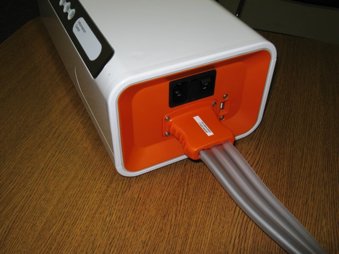
Click to zoom
Application Details
- Equipment Class
- DXX - Part 15 Low Power Communication Device Transmitter
- Date of Grant
- Jul 16, 2014
- Application Purpose
- Original Equipment
- Date of Application
- Jul 15, 2014
- Equipment Note
- Dabir Patient Support System
- Frequency Range
- 13.56000000 - 13.56000000
- Company
- Dabir Surfaces, Inc.
- Country
- United States
Documents & Files
Document Text
Text extracted from the exhibit documents filed with the FCC. Open a document above to read the original.
Users Manual
Instructions For Use CA-9001 (Hose Assembly) CA-9002 (Power Cord) CA-1001 (Controller Starter Kit) DA-101884 (Surgical Overlay) DA-303584 (MedSurg Bed Overlay) MC-303584 (MedSurg Bed Overlay-Micro) Patent Pending DOC# R01-0006-00004-AA 1 Introduction Page # 1.1 Important Before You Start 3 1.2 Safety Warnings 3 1.3 Labels and Descriptions 4-6 1.4 About this Manual 7 1.5 Indications of Use 7 1.6 Contraindications 7 1.7 About the Dabir System 8 1.8 How it Works 8 2 Components of the Dabir Surfaces Overlay System 2.1 Pneumatic Controller, Hose Assembly, and Accessories 9 2.2 Overlays 10 3 Setting up the System 3.1 Pneumatic Controller Pre-Assembly 11 3.2 System Installation 12-14 4 Operating the Dabir System 15 5 Setting the Cycle Speed and Firmness Modes 5.1 Setting Cycle Speed 16 5.2 Setting Overlay Firmness 17 6 Interrupting, Rapid Deflate and Resuming Operation 18 7 Information Center: Error Codes and Alarms 19-20 8 Cleaning Procedures 21 9 Routine Maintenance 21 10 Troubleshooting 22 11 Specification Sheets 23-28 12 Limited Warranty 29-30 13 Contact Information 31 Table of Contents 2 DOC# R01-0006-00004-AA 1.1 Important Before You Start • Please read entire manual carefully and completely before using. • As with any device, failure to carefully read and follow all instructions and safety information prior to use may result in decreased product performance or failure. 1.2 Safety Warnings • It is the responsibility of the caregiver to ensure that the user can operate this product safely. • Power “OFF” or “STOP” Pneumatic Controller for cardiac arrest events. The unit is not intended for use during CPR. (See Section 6) • Properly route and secure Power Cord and hoses to avoid trip hazard. • Maintain accessibility to Power Cord such that it can be easily unplugged. • The Dabir System must be cleaned using the outlined guidelines within this manual. Cleaning conditions that do not reflect the recommended cleaning process may result in irreparable damage. • Disconnect the Pneumatic Controller from the wall power source prior to cleaning and inspecting. • Do not immerse or allow liquid to enter any part of the Pneumatic Controller. • Keep DabirAIR Micropressure Overlay vent free and clear of liquids, contamination and debris to avoid over inflation. • Do not operate the Pneumatic Controller in the presence of flammable liquids or gases. • Only use the DabirAIR Pneumatic Controller with manufacturer approved Overlays and Accessories to ensure proper system function. • The DabirAIR Micropressure and DabirAIR Microclimate products are OVERLAYS, and are not intended to be used without an underlying support mattress or pad. • Do not block air intake ports on the bottom of the Pneumatic Controller or the exhaust vent under the handle. • Do not place Pneumatic Controller on top of loose articles which may block air intake ports. • System must be at room temperature prior to operation. Allow Pneumatic Controller and Overlay to acclimate to room temperature for one hour prior to operation. 3 WARNING: No modification of this equipment is allowed. DOC# R01-0006-00004-AA • Do not place the Pneumatic Controller in direct sunlight. • The Pneumatic Controller must be stored and operated within designed operating conditions specified in this manual. Operating the Pneumatic Controller outside these ranges may cause damage to the device which could result in premature failure. • The Pneumatic Controller must be used with specified operating wall currents. All other alternative power sources and currents may result in irreparable damage to the system and possible hazardous event to the patient or caregiver. • Equipment may be hazardous if misused. • Modification of the device voids warranty and may compromise intended function. Service should be performed exclusively by the manufacturer or manufacturer’s representative. • If Pneumatic Controller is damaged during the shipping process, please contact the manufacturer for appropriate action. • If Pneumatic Controller is dropped during use with noticeable damage, please remove from service and contact the manufacturer for appropriate action. • Do not transport or carry the Pneumatic Controller with an Overlay attached. • This device requires the use of a shielded Power Cord for compliance with emissions limits. Do not operate device without manufacturer supplied Power Cord. • Do not use in an MRI environment. • Turn Dabir System “OFF” during patient transfer and before patient positioning. • It is the responsibility of the caregiver to adequately secure and protect the patient against patient falls. • Do not place the Pneumatic Controller in direct sunlight. • The Pneumatic Controller must be stored and operated within designed operating conditions specified in this manual. Operating the Pneumatic Controller outside these ranges may cause damage to the device which could result in premature failure. • The Pneumatic Controller must be used with specified operating wall currents. All other alternative power sources and currents may result in irreparable damage to the system and possible hazardous event to the patient or caregiver. • Equipment may be hazardous if misused. • Modification of the device voids warranty and may compromise intended function. Service should be performed exclusively by the manufacturer or manufacturer’s representative. • If Pneumatic Controller is damaged during the shipping process, please contact the manufacturer for appropriate action. • If Pneumatic Controller is dropped during use with noticeable damage, please remove from service and contact the manufacturer for appropriate action. • Do not transport or carry the Pneumatic Controller with an Overlay attached. • This device requires the use of a shielded Power Cord for compliance with emissions limits. Do not operate device without manufacturer supplied Power Cord. • Do not use in an MRI environment. • Turn Dabir System “OFF” during patient transfer and before patient positioning. • It …
Text truncated - open the document above for the full version.
Cover Letter(s)
FCC ID: 2ACRH-110024 D.L.S. ELECTRONIC SYSTEMS, INC. 166 South Carter Street Genoa City, WI 53128 July 14, 2014 FCC Authorization & Evaluation Division 7435 Oakland Mills Road Columbia, Maryland 21046 Gentlemen: We are submitting for Dabir Surfaces, Inc., a Dabir Patient Support System 9' Hose Assembly, Model Number: CA-9001, with an FCC ID: 2ACRH-110024 for Certification. This unit has been tested and complies to Part 15, Subpart C. If there are any questions in regard to this application, please call D.L.S. Electronic Systems, Inc. at (262) 279- 0210. Enclosed you will find a copy of our test report with the information and results of tests that is required under Part 15, Section 15.225. Please note that the 9' Hose Assembly is a separate, replaceable part of the Dabir Patient Support System. That piece contains the 13.56MHz RFID which requires FCC certification. Thank you for your assistance in this matter. Sincerely, William M. Stumpf DLS/js
Cover Letter(s)
166 South Carter Street, Genoa City, WI 53128 Request for Confidentiality Date: July 1, 2014 FCC Authorization & Evaluation Division 7435 Oakland Mills Road Columbia, Maryland 21046 RE: Certification Application FCC ID: 2ACRH-110024 Pursuant to 47 CFR Section 0.459 Dabir Surfaces, Inc. understands that requests for non disclosure and confidential treatment is being made for the following information as stated under the Code of Federal Regulations Chapter 47, Part 0.459: • Block Diagram • Schematics • Operational Description The above materials contain trade secrets, proprietary and technical information that would customarily be guarded from competitors under 47 CFR section 0.457(d)(2). Disclosure or publication of any portion of this company confidential material to other parties could cause substantial competitive harm and provide unjustified benefits for competitors. Dabir Surfaces, Inc. understands that pursuant to 47 CFR section 0.457(d)(1)(ii) disclosure of the applicant and all accompanying documentation will not be made before the date of the grant. Thank you for your attention to this matter. Signatory William M. Stumpf OATS Manager D.L.S. Electronic Systems, Inc.
External Photos
External Photos Company: Dabir Surfaces, Inc. Model: CA-9001 Hose Assembly connected to Controller ID Location (with generic label example) External Photos Company: Dabir Surfaces, Inc. Model: CA-9001 Transmitter enclosure - Side 1 Side 2
ID Label/Location Info
Model # CA-9001 9’ Hose Assembly Input: 5VDC 250mA 7447 West Wilson Ave Harwood Heights, IL 60706 (Ph) 1-885-478-0694 www.dabir-surfaces.com IC: 11968A-110024 FCC ID: 2ACRH-110024 NOTES: 1. COLORS: • WHITE: PMS P-1-1C • BLACK: PMS Black 2 2X • ORANGE: PMS 021 • BLUE/GRAY: PMS 7542 • BLUE: PMS 301 2. MATERIAL: 0.010” PROTEK POLYESTER 3. ADHESIVE: 3M-468 4. REFERENCE R01-0006-00056.AI FOR MASTER GRAPHICS AA D C A B C D 1 2 3 4 5 6 78 8 7 56 4 3 2 1 DATE:APPROVED BY: SHEET: UNLESS O TH ERWISE S PECIFIED: BE USED FOR MANUFACTURE OR ANY OTHER PURPOSE WITHOUT THE WRITTEN CONSENT OF DABIR SURFACES. SCALE: 7447 W. Wilson Ave. REV: Harwood Heights, IL 60706 PART #: B SIZE: DATE: TITLE: DATE: CHECKED BY: DRAWN BY: STAMP: NONE WEIGHT: SEE NOTES FINISH: TLC MATERIAL: PROPRIETARY AND CONFIDENTIAL 0.005"] 1:1 R01-0006-00056 1 of 1 JLR DIMENSIONS ARE IN milli meters [in] TOLERANCES: ANGULAR: 1 X 1.0mm [ 0.040"] X.X 0.5mm [0.020"] X.XX 0.25mm [ 0.010"] X.XXX 0.10mm [ THE INFORMATION ENCLOSED IN THIS DOCUMENT IS PROPRIETARY TO DABIR SURFACES INC. AND MAY NOT DEVICE LABEL (9’ HOSE ASSEMBLY) REVISION HISTORY REV.APP. DATE AA INITIAL RELEASETLC NA ECODESCRIPTIONBY 04/14/2014 04/14/2014 Model # CA-9001 9’ Hose Assembly Input: 5VDC 250mA 7447 West Wilson Ave, Harwood Heights, IL 60706 1-885-478-0694 www.dabir-surfaces.com IC: 11968A-110024 FCC ID: 2ACCA-110024 6.76 25.78 38.10 6.41 25.38 31.75 R 3.18 R 1.58 TRANSPARENT WINDOW WHITE BACKGROUND Label placement only (incorrect FCC ID number)
Internal Photos
Internal Photos Company: Dabir Surfaces, Inc. Model: CA-9001 RFID tag removed Cover removed Internal Photos Company: Dabir Surfaces, Inc. Model: CA-9001 RFID Tag Hoses removed Internal Photos Company: Dabir Surfaces, Inc. Model: CA-9001 Inside Covers Circuit Board - Side 1 Internal Photos Company: Dabir Surfaces, Inc. Model: CA-9001 Circuit Board - Side 2
Test Report
166 South Carter, Genoa City, WI 53128 Page 1 of 46 Company: Dabir Surfaces, Inc. Model Tested: CA-9001 Report Number: 20054 Project Number: 6545 i. Cover Page Code of Federal Regulations 47 Part 15 – Radio Frequency Devices Subpart C – Intentional Radiators Section 15.225 Operation within the band 13.110 – 14.010 MHz THE FOLLOWING MEETS THE ABOVE TEST SPECIFICATION Formal Name: Dabir Patient Support System 9' Hose Assembly Kind of Equipment: Patient Support System Frequency Range: 13.56 MHz Test Configuration: Tabletop Model Number(s): CA-9001 Model(s) Tested: CA-9001 Serial Number(s): Controller: 16-14008 with prototype 9' Hose Assembly Date of Tests: May 1st to May 7th, 2014 Test Conducted For: Dabir Surfaces, Inc. 24585 Evergreen Rd. Southfield, MI 48075, USA NOTICE: “This test report relates only to the items tested and must not be used by the client to claim product endorsement by NVLAP or any agency of the U.S. Government”. Please see the "Description of Test Sample" page listed inside of this report. © Copyright 1983 - 2014 D.L.S. Electronic Systems, Inc. COPYRIGHT NOTICE This report must not be reproduced (except in full), without the approval of D.L.S. Electronic Systems, Inc. 166 South Carter, Genoa City, WI 53128 Page 2 of 46 Company: Dabir Surfaces, Inc. Model Tested: CA-9001 Report Number: 20054 Project Number: 6545 ii. Signature Page SIGNATURE PAGE Tested By: Craig Brandt Test Engineer Reviewed By: William Stumpf OATS Manager Approved By: Brian Mattson General Manager 166 South Carter, Genoa City, WI 53128 Page 3 of 46 Company: Dabir Surfaces, Inc. Model Tested: CA-9001 Report Number: 20054 Project Number: 6545 iii. Table of Contents Table of Contents i. Cover Page .......................................................................................................................................1 ii. Signature Page .................................................................................................................................2 iii. Table of Contents .............................................................................................................................3 iv. NVLAP Certificate of Accreditation ...............................................................................................4 1.0 Summary of Test Report ..................................................................................................................5 2.0 Introduction ......................................................................................................................................5 3.0 Test Facilities ...................................................................................................................................5 4.0 Description of Test Sample ..............................................................................................................6 5.0 Test Equipment ................................................................................................................................8 6.0 Test Arrangements ...........................................................................................................................9 7.0 Test Conditions ................................................................................................................................9 8.0 Modifications Made To EUT For Compliance ................................................................................9 9.0 Additional Descriptions .................................................................................................................10 10.0 Results ............................................................................................................................................10 11.0 Conclusion .....................................................................................................................................10 Appendix A – Test Photos .........................................................................................................................11 Appendix B – Measurement Data ..............................................................................................................17 1.0 Occupied Bandwidth – 20 dB ................................................................................................... 17 2.0 Radiated Emissions ................................................................................................................... 19 2.0a Emission Mask .......................................................................................................................... 20 2.0b Radiated, 9kHz – 30MHz ......................................................................................................... 21 2.0c Radiated, 30MHz - 1000MHz .................................................................................................. 24 3.0 Frequency Stability ................................................................................................................... 30 4.0 AC line Conducted Emissions .................................................................................................. 41 166 South Carter, Genoa City, WI 53128 Page 4 of 46 Company: Dabir Surfaces, Inc. Model Tested: CA-9001 Report Number: 20054 Project Number: 6545 iv. NVLAP Certificate of Accreditation 166 South Carter, Genoa City, WI 53128 Page 5 of 46 Company: Dabir Surfaces, Inc. Model Tested: CA-9001 Report Number: 20054 Project Number: 6545 1.0 Summary of Test Report It was determined that the Dabir Surfaces, Inc. Dabir Patient Support System 9' Hose Assembly, Model: CA-9001, complies with the requirements of CFR 47 Part 15 Subpart C Section 15.225. Subpart C Section 15.225 Applicable Technical Requirements Tested: Section Description Procedure Note Compliant? Informational 20 dB Emission Bandwidth ANSI C63.10-2009 Section 6.9.1 1 Yes FCC 15.225 & 15.209 Radiated Emissions ANSI C63.4-2009 & ANSI C63.10-2009 1 Yes FCC 15.225(e) Frequency Stab…
Text truncated - open the document above for the full version.
Test Setup Photos
166 South Carter, Genoa City, WI 53128 Page 1 of 6 Manufacturer: Dabir Surfaces, Inc. Model Tested: CA-9001 Project Number: 6545 Photo Information and Test Setup: Item 0: Dabir Patient Support System 9' Hose Assembly, Model: CA-9001 (RFID in 9' Hose Assembly) Item 1: Overlay Assembly Itme 2: Shielded AC Power Cord, 1.5 meters long Item 3: Shielded Cable/Hose Assembly, 2.5 meters long - plastic Item 4: EUT - Controller, Serial Number: 16-14008 Radiated Emissions – Front 166 South Carter, Genoa City, WI 53128 Page 2 of 6 Manufacturer: Dabir Surfaces, Inc. Model Tested: CA-9001 Project Number: 6545 Radiated Emissions – Back - Positions 1 & 2 166 South Carter, Genoa City, WI 53128 Page 3 of 6 Manufacturer: Dabir Surfaces, Inc. Model Tested: CA-9001 Project Number: 6545 Radiated Emissions – Back - Position 3 166 South Carter, Genoa City, WI 53128 Page 4 of 6 Manufacturer: Dabir Surfaces, Inc. Model Tested: CA-9001 Project Number: 6545 Frequency Stability 166 South Carter, Genoa City, WI 53128 Page 5 of 6 Manufacturer: Dabir Surfaces, Inc. Model Tested: CA-9001 Project Number: 6545 AC line Conducted Emissions – Front 166 South Carter, Genoa City, WI 53128 Page 6 of 6 Manufacturer: Dabir Surfaces, Inc. Model Tested: CA-9001 Project Number: 6545 AC line Conducted Emissions – Back
Contact Information
Applicant
Dave Alan Dzioba(General Manager)
Technical Contact
D. L. S. Electronic Systems, Inc.William M. Stumpf
[email protected]262-279-0210
166 South Carter Street · Genoa City, Wisconsin · United States
Test Firm
DLS Electronic Systems, Inc.William Stumpf
Technical Specifications
| # | Rule Parts | Frequency Range | Power Output |
|---|---|---|---|
| 1 | 15C | 13.56 MHz - 13.56 MHz | - |