2ACVBKCD24T012.4G RF Module
SHENZHEN KECHUANGDA MICRO ELECTRONICS CO.,LTD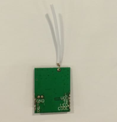
Click to zoom
Application Details
- Equipment Class
- DXX - Part 15 Low Power Communication Device Transmitter
- Date of Grant
- Sep 22, 2014
- Application Purpose
- Original Equipment
- Date of Application
- Sep 22, 2014
- Equipment Note
- 2.4G RF Module
- Frequency Range
- 2402.00000000 - 2480.00000000
- Country
- China
Documents & Files
Document Text
Text extracted from the exhibit documents filed with the FCC. Open a document above to read the original.
Users Manual
KCD24T01 RF Module production instruction manual 1. Summary: KCD24T01 RF Module is a RF transceiver module that can work in the 2.4GHZ band for toy remote control car 2. Electrical parameters: Operating voltage:DC 4.5V(BATTERY POWERED) Operating current:21ma Operating frequency: 2402MHZ-2480MHZ The RF output maximum power: -14dbm Modulation mode: GFSK The modulation frequency deviation maximum: 280KHZ 3.Functional description: Modules are installed on a PCB board,to connect power switch by turning on the switch on the base board. At the mean time, there are 4 keys and 1 LED light on the board is also connected to corresponding pin on module. LED light will slowly flash at first after switching on the power and module begins to match codes. Then turn on the other receiving module power, LED light will flash quickly off for 2 seconds after 1-3 seconds later which means the connection between the two modules has been established, codes have been matched. Then proceed into the normal mode, the corresponding orders can be sent out as RF signals via transmitting antenna by pressing buttons of forward, backward, turn left and turn right. modula powered by AA battery.Note: this EUT is powered by the battery only(1.5V*3AA) FCC Caution: This device complies with part 15 of the FCC Rules. Operation is subject to the following two conditions: (1) This device may not cause harmful interference, and (2) this device must accept any interference received, including interference that may cause undesired operation. This device and its antenna(s) must not be co-located or operating in conjunction with any other antenna or transmitter. FCC RF Exposure Statement The modular is comply with any applicable RF exposure requirements. An intentional radiator shall be designed to ensure that no antenna other than that furnished by the responsible party shall be used with the device. The use of a permanently attached antenna or of an antenna that uses a unique coupling to the intentional radiator shall be considered sufficient to comply with the provisions of this Section. The manufacturer may design the unit so that a broken antenna can be replaced by the user, but the use of a standard antenna jack or electrical connector is prohibited. This requirement does not apply to carrier current devices or to devices operated under the provisions of Sections 15.211, 15.213, 15.217, 15.219, or 15.221. Further, this requirement does not apply to intentional radiators that must be professionally installed, such as perimeter protection systems and some field disturbance sensors, or to other intentional radiators which, in accordance with Section 15.31(d), must be measured at the installation site. However, the installer shall be responsible for ensuring that the proper antenna is employed so that the limits in this Part are not exceeded. This device complies with part 15.203. FCC Statements of Compliance Statement and Conditions of Modular Compliance FCC NOTICE (FCC ID: 2ACVBKCD24T01) This device complies with the rules set forth in Part 15 by the Federal Communications Commission. Operation is subject to the following two conditions: 1) This device may not cause harmful interference 2) This device must accept any interference received, including interference that may cause undesired operation. Any changes or modifications not expressly approved by SHENZHEN KECHUANGDA MICRO ELECTRONICS CO.,LTD could void the user’s authority to operate the equipment. The KCD24T01 module is provided with an Limited FCC Modular Certification(powered by battery only). This certification may be install in an end-user product, negating the need for FCC part 15 intentional radiator testing on this module, provided that the following guidelines are met: 1. The module must not be modified in any way. Coupling of external circuitry must not bypass the provided connectors. 2 End product must be externally labeled with “Contains FCC ID: 2ACVBKCD24T01” 3. The antenna used for this transceiver must not be co-located or operating in conjunction with any other antenna or transmitter. 4. The integrator must not provide any information to the end-user on how to install or remove the module from the end-product. The integrator is required to perform unintentional radiator testing on the final product per FCC sections 15.107 and 15.109.
Cover Letter(s)
SHENZHEN KECHUANGDA MICRO ELECTRONICS CO.,LTD FCC Confidentiality Request Number: CF303 Version: V01 Date: 01-02-2010 To the FCC and FCC TCB handling this application for certification Pursuant to 47 CFR Section 0.459(a) & (b), we, (the applicant / grantee) Company name SHENZHEN KECHUANGDA MICRO ELECTRONICS CO.,LTD Addresss 10F, Qinghua information Port A, North Highkeyuan Road, Nanshan District City Shenzhen Country China request non-disclosure and confidential treatment for our certification under: Grantee Code Product Number FCC ID: 2ACVB KCD24T01 of the following materials submitted within this certification application: (please cross what is applicable, or add other documents) x Operational Description x Block Diagrams x Schematics Diagrams Bill of Materials Above materials contain secrets, proprietary and technical information, which would customarily be guarded from competitors under 47 CFR, section 0.457(d)(2). Disclosure or publication or any portion of this company confidential material to other parties could cause substantial competitive harm and provide unjustified benefits for competitors. We understand that pursuant to 47 CFR section 0.457(d)(1)(ii) disclosure of the applicant and all accompanying documentation will not be made before the date of the grant. Attestation: City and Country: Date: Name: (this must be a person) Function: Signature: (or official company stamp) shenzhen 2014.8.7 LV QUN Administration Staff
Cover Letter(s)
FCC Modular Approval Request To the FCC or FCC TCB handling this application Hereby we, Company (grantee) SHENZHEN KECHUANGDA MICRO ELECTRONICS CO.,LTD Addresss 10F, Qinghua information Port A, North Highkeyuan Road, Nanshan District City / ZIP / State / Country Shenzhen China request modular approval for the certification of our equipment within this application, identified by: FCC ID: 2ACVBKCD24T01 The table below contains justification for limited modular approval of this equipment. Requirement per DA 00-1407 Explanation from grantee 1. The modular transmitter must have its own RF shielding. The modular shielded The modular transmitter must have buffered modulation/data inputs (if such inputs are provided) to ensure that the module will comply with Part 15 requirements under conditions of excessive data rates or over-modulation. Max 100 bytes.GFSK modulation. Power part: The VS4432 is a positive voltage r egulator with a low dropout voltage and low noise output. In addition, this d evice offers a very low ground current of 100μA at 21mA output. The VS4432 has an initial tolerance of less than 1% max and a logic compatible ON/OFF switched input. When disabled, power consumption drops to nearly zero. Othe r key features include reverse battery protection, urrent limit, and thermal shu tdown. The VS4432 includes a reference bypass pin for optimal low noise out put performance. With its very low output temperature coefficient, this device also makes a superior low power voltage reference. 2. The modular transmitter must have its own power supply regulation. the modular transmitter have its own power supply regulation DC 4.5V,it is powered by “AA” battery The modular transmitter must comply with the antenna requirements of Section 15.203 and 15.204(c). The antenna must either be permanently attached or employ a “unique” antenna coupler (at all connections between the module and the antenna, including the cable).. The modular is comply with the antenna requirements of section 15.203 and 15.204c Reverse SMA This aspect is further covered in the 0peration Description 3. The modular transmitter must be tested in a stand-alone configuration, i.e., the module must not be inside another device during testing. This is intended to demonstrate that the module is capable of complying with Part 15 emission limits regardless of the device into which it is eventually installed. The modular was tested in a stand-alone configuration. 4. The modular transmitter must be labeled with its own FCC ID number, and, if the FCC ID is not visible when the module is installed inside another device, then the outside of the device into which the module is installed must also display a label referring to the enclosed module. This exterior label can use wording such as the following: “Contains Transmitter Module FCC ID: 2ACVBKCD24T01” or “Contains FCC ID: 2ACVBKCD24T01.” Any similar wording that expresses the same meaning may be used. The Grantee may either provide such a label, an example of which must be included in the application for equipment authorization, or, must provide adequate instructions along with the module which explain this requirement. In the latter case, a copy of these instructions must be included in the application for equipment authorization. The modular was labelled with its own FCC ID 5. The modular transmitter must comply with any specific rule or operating requirements applicable to the transmitter and the manufacturer must provide adequate instructions along with the module to explain any such requirements. A copy of these instructions must be included in the application for equipment authorization. For example, there are very strict operational and timing requirements that must be met before a transmitter is authorized for operation under Section 15.231. For instance, data transmission is prohibited, except for operation under Section 15.231(e), in which case there are separate field strength level and timing requirements. Compliance with these requirements must be assured. The modular is comply with any specific or operating requirements applicable to the transmitter. 6. The modular transmitter must comply with any applicable RF exposure requirements. For example, FCC Rules in Sections 2.1091, 2.1093 and specific Sections of Part 15, including 15.319(i), 15.407(f), 15.253(f) and 15.255(g), require that Unlicensed PCS, UNII and millimetre wave devices perform routine environmental evaluation for RF Exposure to demonstrate compliance. In addition, spread spectrum transmitters operating under Section 15.247 are required to address RF Exposure compliance in accordance with Section The modular is comply with any applicable RF exposure requirements. This submission is a FCC15.249 application, so this EUT is an extreme low power device and could comply with SAR exemption evaluation always FCC Modular Approval Request 15.247(b)(4). Modular transmitters approved under other Sections of Part 15, when necessary, may also need to address certain RF Exposure concerns, typically by providing specific installation and operating instructions for users, installers and other interested parties to ensure compliance. The modular transmitter must be tested in a stand-alone configuration, i.e. , the module must not be inside another device during testing for compliance with part 15 requirements. Unless the transmitter module will be battery powered, it must comply with the AC line conducted requirements found in § 15.207. AC or DC power lines and data input/output lines connected to the module must not contain ferrites, unless they will be marketed with the module (see § 15.27(a)). The length of these lines shall be the length typical of actual use or, if that length is unknown, at least 10 centimeters to insure that there is no coupling between the case of the module and supporting equipment. Any accessories, peripherals, or support equipment connected to the module during testing shall be unmodified and commer…
Text truncated - open the document above for the full version.
External Photos
APPENDIX-PHOTOGRAPHS OF EUT CONSTRUCTIONAL DETAILS Photo 1 Photo 2 Photo 3 Photo 4
ID Label/Location Info
FCCID:2ACVBKCD24T01
Internal Photos
Photo 5 Photo 6 Photo 7
Test Report
FCC RADIO TEST REPORT FCC ID: 2ACVBKCD24T01 Product: 2.4G RF Module Trade Name: N/A Model Name: KCD24T01 Serial Model: N/A Prepared for SHENZHEN KECHUANGDA MICRO ELECTRONICS CO.,LTD 10F, Qinghua information Port A, North Highkeyuan Road, Nanshan District, Shenzhen, China Prepared by Shenzhen STONE Testing Technology Co.,Ltd. F/6, Bldg.12, Zhongxing Industrial City, Chuangye Rd., Nanshan District Shenzhen P.R. China Page 2 of 38 Report No.: STT-2014DG0805117F ` TEST RESULT CERTIFICATION Applicant’s name................. SHENZHEN KECHUANGDA MICRO ELECTRONICS CO.,LTD Address ................................ . 10F, Qinghua information Port A, North Highkeyuan Road, Nanshan District, Shenzhen, China Manufacture's Name........... . SHENZHEN HUIZHONGDA ELECTRONICE CO., LTD Address ................................ . 5/F, Building B4, Yingtian Industry XiXiang Road BaoAn Distict ShenZhen,China Product description Product name ..........................2.4G RF Module Model and/or type reference .............................................. . KCD24T01 Serial Model: N/A Standards............................ . FCC Part15.249 Test procedure ......................... ANSI C63.4-2003 This device described above has been tested by STT, and the test results show that the equipment under test (EUT) is in compliance with the FCC requirements. And it is applicable only to the tested sample identified in the report. This report shall not be reproduced except in full, without the written approval of STT, this document may be altered or revised by STT, personal only, and shall be noted in the revision of the document. Date of Test............................................ Date (s) of performance of tests ............. 15 Jul. 2014 ~05 Aug. 2014 Date of Issue........................................... 05 Aug. 2014 Test Result............................................... Pass Testing Engineer : (Eric Wang) Technical Manager : (Jerry You) Authorized Signatory : (Jack yu) Page 3 of 38 Report No.: STT-2014DG0805117F ` Table of Contents Page 1 . SUMMARY OF TEST RESULTS 4 1.1 TEST FACILITY 5 1.2 MEASUREMENT UNCERTAINTY 5 2 . GENERAL INFORMATION 6 2.1 GENERAL DESCRIPTION OF EUT 6 2.2 DESCRIPTION OF TEST MODES 8 2.3 BLOCK DIGRAM SHOWING THE CONFIGURATION OF SYSTEM TESTED 9 2.4 DESCRIPTION OF SUPPORT UNITS(CONDUCTED MODE) 10 2.5 EQUIPMENTS LIST FOR ALL TEST ITEMS 11 3 . ANTENNA REQUIREMENT 12 3.1 STANDARD REQUIREMENT 12 3.2 EUT ANTENNA 12 3.3 CONDUCTED EMISSION MEASUREMENT 13 3.3.1 POWER LINE CONDUCTED EMISSION LIMITS 13 3.3.2 TEST PROCEDURE 14 3.3.3 DEVIATION FROM TEST STANDARD 14 3.3.4 TEST SETUP 14 3.2.5 TEST RESULT 15 3.4 RADIATED EMISSION MEASUREMENT 16 3.4.1 RADIATED EMISSION LIMITS 16 3.4.2 TEST PROCEDURE 17 3.4.3 DEVIATION FROM TEST STANDARD 17 3.4.4 TEST SETUP 18 3.4.5 TEST RESULTS (BELOW 30MHZ) 20 3.4.6 TEST RESULTS (BETWEEN 30 – 1000 MHZ) 21 3.4.7 TEST RESULTS (ABOVE 1000 MHZ) 23 3.4.8 TEST RESULTS (RESTRICTED BANDS REQUIREMENTS) 29 4 . BANDWIDTH TEST 33 4.1 TEST PROCEDURE 33 4.2 DEVIATION FROM STANDARD 33 4.3 TEST SETUP 33 4.4 TEST RESULTS 34 5 . EUT TEST PHOTO 37 APPENDIX-PHOTOGRAPHS OF EUT CONSTRUCTIONAL DETAILS Page 4 of 38 Report No.: STT-2014DG0805117F ` 1. SUMMARY OF TEST RESULTS Test procedures according to the technical standards: FCC Part15, Subpart C (15.249) Standard Section Test Item Judgment Remark 15.207 Conducted Emission N/A 15.203 Antenna Requirement Pass 15.249 Radiated Spurious Emission Pass 15.205 Band Edge Emission Pass 15.249 Occupied Bandwidth Pass NOTE: (1)” N/A” denotes test is not applicable in this Test Report Page 5 of 38 Report No.: STT-2014DG0805117F ` 1.1 TEST FACILITY Shenzhen STONE Testing Technology Co.,Ltd. Add. : F/1, Bldg.12, Zhongxing Industrial City, Chuangye Rd., Nanshan District Shenzhen China FCC Registration No.: 323508; IC Registration No.: 11043A 1.2 MEASUREMENT UNCERTAINTY The reported uncertainty of measurement y ± U,where expended uncertainty U is based on a standard uncertainty multiplied by a coverage factor of k=2,providing a level of confidence of approximately 95 %。 No. Item Uncertainty 1 Conducted Emission Test ±1.38dB 2 RF power,conducted ±0.16dB 3 Spurious emissions,conducted ±0.21dB 4 All emissions,radiated(<1G) ±4.68dB 5 All emissions,radiated(>1G) ±4.89dB 6 Temperature ±0.5°C 7 Humidity ±2% Page 6 of 38 Report No.: STT-2014DG0805117F ` 2. GENERAL INFORMATION 2.1 GENERAL DESCRIPTION OF EUT Equipment 2.4G RF Module Trade Name N/A Model Name KCD24T01 Serial Model N/A Model Difference All the models are the same circuit and RF module, except the model names. Product Description The EUT is a 2.4G RF Module Operation Frequency: 2402~2480MHz Modulation Type: GFSK Antenna Designation: Extension wire Antenna Antenna Gain(Peak) 0 dBi Field Strength 89.86 dBuv/m@3m(AVG) Based on the application, features, or specification exhibited in User's Manual, the EUT is considered as an ITE/Computing Device. More details of EUT technical specification, please refer to the User's Manual. Channel List Please refer to the Note 2. Adapter N/A Battery DC 4.5V Note: 1. For a more detailed features description, please refer to the manufacturer’s specifications or the User's Manual. Page 7 of 38 Report No.: STT-2014DG0805117F ` 2. Channel Frequency (MHz) 01 2402 02 2440 03 2480 3. Table for Filed Antenna Ant . Brand Model Name Antenna Type Connector Gain (dBi) NOTE 1 N/A N/A Integral Wire Antenna N/A 0 Antenna Page 8 of 38 Report No.: STT-2014DG0805117F ` 2.2 DESCRIPTION OF TEST MODES To investigate the maximum EMI emission characteristics generates from EUT, the test system was pre-scanning tested base on the consideration of following EUT operation mode or test configuration mode which possible have effect on EMI emission level. Each of these EUT operation mode(s) or test configuration mode(s) mentioned above was evaluated respectively. Pretest Mode Description Mode 1 TX CH 01 Mode 2 TX CH 02 Mode 3 TX CH 03 For Conducted Emission Final Test Mode Description / / For Radiat…
Text truncated - open the document above for the full version.
Test Setup Photos
Page 37 of 38 Report No.: STT-2014DG0805117F ` 5. EUT TEST PHOTO Radiated Measurement Photos Page 38 of 38 Report No.: STT-2014DG0805117F `
Contact Information
Applicant
LV QUN(Administration Staff)
Test Firm
Shenzhen STONE Testing Technology Co.,Ltd.Ethan Chen
[email protected]8607552658
Technical Specifications
| # | Rule Parts | Frequency Range | Power Output |
|---|---|---|---|
| 1 | 15C | 2.40 GHz - 2.48 GHz | - |