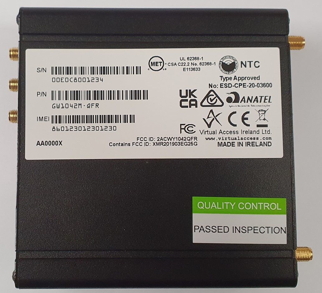
2ACWY1042QFRThe GW1000M Series router is a compact and rugged LTE router with WIFI
Virtual Access Ireland Limited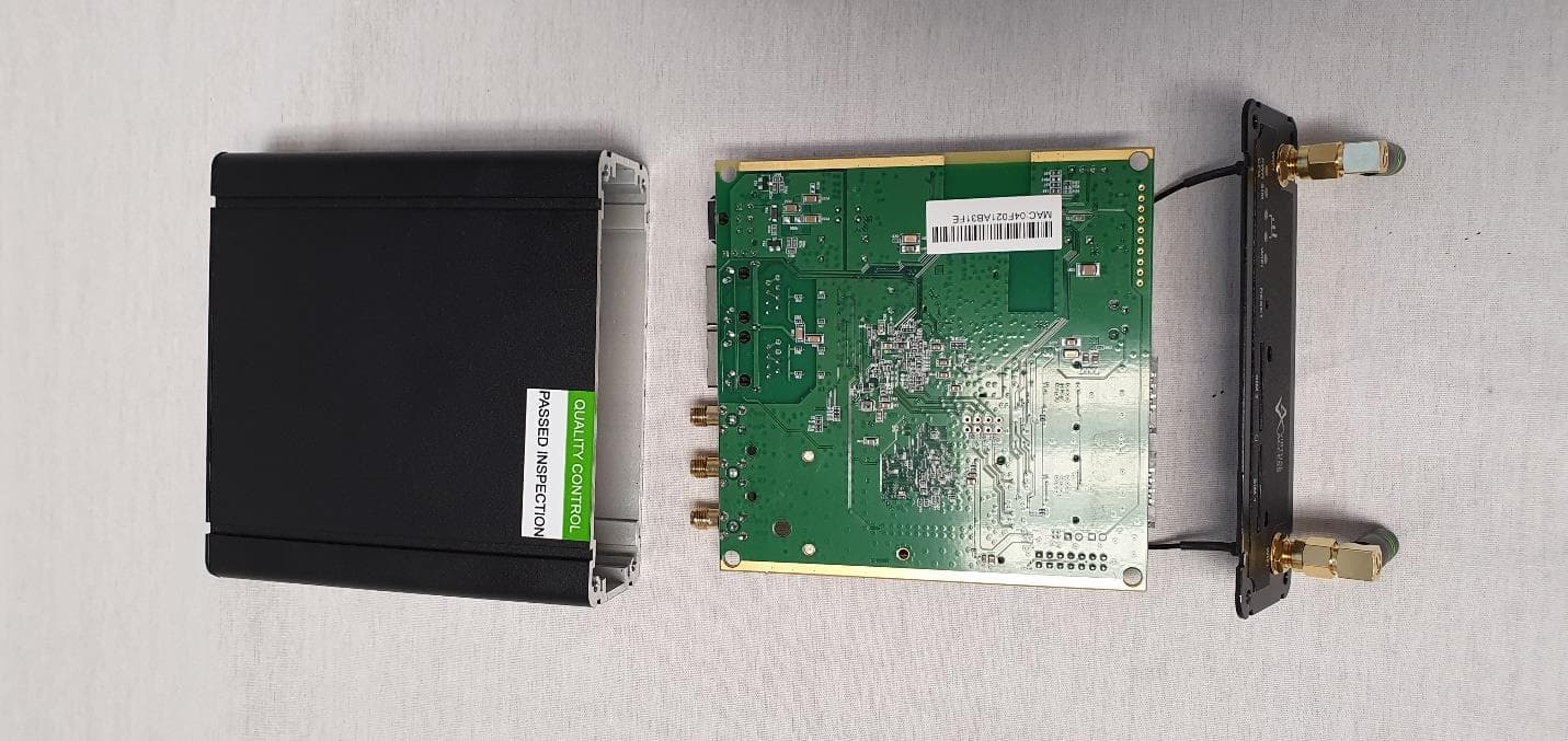
Click to zoom
Application Details
- Equipment Class
- DTS - Digital Transmission System
- Date of Grant
- Apr 16, 2023
- Application Purpose
- Original Equipment
- Date of Application
- Apr 16, 2023
- Equipment Note
- The GW1000M Series router is a compact and rugged LTE router with WIFI
- Frequency Range
- 2412.00000000 - 2462.00000000
- Country
- Ireland
Documents & Files
Document Text
Text extracted from the exhibit documents filed with the FCC. Open a document above to read the original.
Users Manual
G W1000M Series User Manual Issue: Date: 2.7 30 March 2023 Table of Contents _______________________________________________________________________________________________________ _______________________________________________________________________________________________________ © Virtual Access 2023 GW1000M Series User Manual Issue: 2.7 Page 2 of 23 1 Introduction ............................................................................................... 10 1.1 Document scope ..................................................................................... 10 1.2 Using this documentation ......................................................................... 10 1.3 Safety ................................................................................................... 12 1.4 Product disposal ..................................................................................... 13 1.5 Approvals and statements ........................................................................ 13 2 GW1000M Series router hardware .............................................................. 16 2.1 GW1000M Series router hardware model features ....................................... 16 2.2 GW1000M Series router dimensions .......................................................... 17 2.3 GSM technology ...................................................................................... 17 2.4 WiFi technology ...................................................................................... 18 2.5 Power supply .......................................................................................... 18 2.6 Compliance ............................................................................................ 18 2.7 Operating temperature range ................................................................... 18 2.8 Antenna ................................................................................................. 18 2.9 GW1000M Series components .................................................................. 19 2.10 Inserting a SIM card ................................................................................ 20 2.11 Connecting the SIM lock .......................................................................... 20 2.12 Connecting cables ................................................................................... 20 2.13 Connecting the antenna ........................................................................... 20 2.14 Installing the GW1000M ........................................................................... 20 2.15 Installing the GW1000M on a wall ............................................................. 20 2.16 Powering up ........................................................................................... 20 2.17 Reset button .......................................................................................... 21 3 GW1000M Series LED behaviour ................................................................. 22 3.1 Main LED behaviour................................................................................. 22 3.2 GW1000M Series Ethernet port LED behaviour ............................................ 23 1: Introduction _______________________________________________________________________________________________________ 1 Introduction This user manual describes the features and how to configure Virtual Access GW1000M Series routers. Virtual Access GW1000M Series routers enable 3G or LTE connectivity in vehicles such as buses, taxis and fleet vehicles for applications such as passenger WiFi internet access, telemetry and employee WiFi access to corporate network services. Designed for managed network providers, GW1000M Series routers provide secure WAN connectivity for internet and private networking environments over 3G or 4G broadband paths and incorporate optional 802.11n WiFi connectivity. 1.1 Document scope This document covers models in the GW1000M Series. The Virtual Access GW1000M Series router is a compact 3G, 4G/LTE router with WiFi, designed with a rugged metal housing for use in vehicles and a wide range of site-based applications. GW1032M: Dual Ethernet, 3G, Dual SIM, Dual WiFi SMA female connectors GW1042M: Dual Ethernet, 4G/LTE, Dual SIM, Dual WiFi SMA female connectors 1.2 Using this documentation You can configure your router using either the router’s web interface or via the command line using UCI commands. Each chapter explains first the web interface settings, followed by how to configure the router using UCI. The web interface screens are shown along with a path to the screen for example, ‘In the top menu, select Service -> SNMP.’ followed by a screen grab. After the screen grab there is an information table that describes each of the screen’s fields. 1.2.1 Information tables We use information tables to show the different ways to configure the router using the router’s web and command line. The left-hand column shows three options: •Web: refers the command on the router’s web page, •UCI: shows the specific UCI command, and •Opt: shows the package option. The right-hand column shows a description field that describes the feature’s field or command an d shows any options for that feature. Some features have a drop-down menu an d the options are described in a table within the description column. The default value is shown in a grey cell. _______________________________________________________________________________________________________ © Virtual Access 2023 GW1000M Series User Ma nual Issue: 2.7 Page 10 of 23 1: Introduction _______________________________________________________________________________________________________ _______________________________________________________________________________________________________ © Virtual Access 2023 GW1000M Series User Manual Issue: 2.7 Page 11 of 23 Values for enabling and disabling a feature are varied throughout the web interface, for exam…
Text truncated - open the document above for the full version.
Users Manual
GW1000M Series General and Safety Information GW1000M GW1042M Issue: Draft 2 Date: 12 October 2021 Table of Contents _______________________________________________________________________________________________________ _______________________________________________________________________________________________________ © Virtual Access 2021 Confidential Page 2 of 23 1 Introduction ................................................................................................. 3 1.1 Product information ................................................................................... 3 1.2 GW1000M Series router overview and features ............................................. 3 1.3 GW1000M Series router dimensions ............................................................ 4 1.4 GSM technology ........................................................................................ 4 2 Virtual Access product safety ....................................................................... 6 2.1 Safety during installation ........................................................................... 6 2.2 Safety during during device operation ......................................................... 6 2.3 Warnings ................................................................................................. 6 2.4 Wireless safety ......................................................................................... 7 2.5 Product disposal ....................................................................................... 7 3 Getting started ............................................................................................. 9 3.1 Serial number ......................................................................................... 10 3.2 Inserting the SIM card ............................................................................. 10 3.3 Connecting the antenna ........................................................................... 10 4 GW1000M Series LED behaviour ................................................................. 12 4.1 Main LED behaviour................................................................................. 12 4.2 GW1000M Series Ethernet port LED behaviour ............................................ 13 1 Accessing the GW1000M Series router ....................................................... 14 5 Upgrading router firmware ......................................................................... 18 5.2 Firmware recovery .................................................................................. 22 6 Troubleshooting ......................................................................................... 23 _______________________________________________________________________________________________________ _______________________________________________________________________________________________________ © Virtual Access 2021 Confidential Page 3 of 23 1 Introduction IMPORTANT! Read this manual and gather all available information on the product. Make sure you understand it fully before connecting the product to a power supply. Check that your application does not exceed the safe operating specifications for this product. 1.1 Product information License and Copyright for Virtual Access managed products include software developed by third parties. The specific license terms and copyright associated with the software are included in each software package respectively. Please visit the product web page for more information. Upon request, the applicable source code will be provided. A nominal fee may be charged to cover shipping and media. Please direct any source code request to your normal sales or support channel. 1.2 GW1000M Series router overview and features The GW1000M Series router can contain either a 3G or 4G wireless modem. The modem together with a SIM card establishes a WAN connection to the Internet or private network. 3G is the third generation of mobile phone standards and technology. It is based on the International Telecommunication Union (ITU) family of standards under the International Mobile Telecommunications programme, IMT-2000. 3G and 4G technologies enable network operators to offer users a wider range of more advanced services while achieving greater network capacity through improved spectral efficiency. Services include wide-area wireless voice telephony, video calls, and broadband wireless data, all in a mobile environment. Data bearers are frame protocols that transport data streams. The GSM (3G) modem supports GPRS, EDGE, HSDPA, HSUPA, UMTS and CSD. The 4G modem supports 4G frequencies and fails over to 3G, GPRS and EDGE technologies. 1.2.1 GW1000M with standard locking DC power connector Figure 1: GW1000M Series router front Figure 2: GW1000M Series router back _______________________________________________________________________________________________________ _______________________________________________________________________________________________________ © Virtual Access 2021 Confidential Page 4 of 23 GW1042M Dual SIM sockets Dual antenna SMA connectors for LTE main and aux GPS antenna with 3.3V active power feed Two 10/100 Mbps Ethernet ports Dual WiFi internal antennas Dual WiFi SMA female connectors Concurrent Access Point and Station mode Metal casing Carrier bracket 1.2.2 GW1000M with isolated DC power connector Figure 3: GW1000M Series router front Figure 4: GW1000M Series router back GW1042M Dual SIM sockets Dual antenna SMA connectors for LTE main and aux GPS antenna with 3.3V active power feed Two 10/100 Mbps Ethernet ports Concurrent Access Point and Station mode Metal casing Carrier bracket 1.3 GW1000M Series router dimensions Unit size: 114W 114D 38Hmm Unit size with carrier: 120W 120D 42Hmm Unit weight: 450g 1.4 GSM technology • LTE • HSPA+ • EDGE/GPRS • GPS _______________________________________________________________________________________________________ ________…
Text truncated - open the document above for the full version.
Attestation Statements
Virtual Access Limited, 9B Beckett Way, Park West Business Park, Dublin 12, D12 PK44, Ireland Co. reg no. 253172 FCC Covered List Attestation Attention: Application Examiner Re: Covered List, located at https://www.fcc.gov/supplychain/coveredlist and 47 CFR parts §2.903 and §2.911(d)(5)(ii) of the FCC rules Applicant: Virtual Access Ireland Ltd. FCC ID: 2ACWY1042QFR To whom it may concern, Virtual Access Ireland Ltd. (“Applicant”) certifies that the equipment for which authorization is sought is not “covered” equipment prohibited from receiving an equipment authorization pursuant to 47 CFR part §2.903 of the FCC rules and does not originate directly or indirectly from any company named on the covered list located in the link above or any subsidiary or affiliate thereof. Applicant further certifies that, as of the date of the filing of the application, the Applicant is not identified on the Covered List as an entity producing “covered” equipment and is not a subsidiary or affiliate of any such entity pursuant to 47 CFR part §1.50002 and required by 47 CFR part §2.911(d)(5)(ii) of the FCC rules. I HEREBY CERTIFY THAT I am authorized to make the representations above on behalf of the Applicant and agree to immediately notify Intertek if there is any change in the status identified above. _________________________ Name: Declan Carew Designation: Managing Director Common seal
RF Exposure Info
Intertek 731 Enterprise Drive Lexington, KY 40510 Tel 859 226 1000 Fax 859 226 1040 www.intertek.com VIRTUAL ACCESS IRELAND LTD. MPE REPORT SCOPE OF WORK MPE CALCULATION ON THE GW1042M-QFR REPORT NUMBER 104922051LEX-001 ISSUE DATE 8/28/2022 PAGES 14 DOCUMENT CONTROL NUMBER Non-Specific EMC Report Shell Rev. December 2017 © 2017 INTERTEK This report is for the exclusive use of Intertek's Client and is provided pursuant to the agreement between Intertek and its Client. Intertek's responsibility and liability are limited to the terms and conditions of the agreement. Intertek assumes no liability to any party, other than to the Client in accordance with the agreement, for any loss, expense or damage occasioned by the use of this report. Only the Client is authorized to copy or distribute this report and then only in its entirety. Any use of the Intertek name or one of its marks for the sale or advertisement of the tested material, product or service must first be approved in writing by Intertek. The observations and test results in this report are relevant only to the sample tested. This report by itself does not imply that the material, product, or service is or has ever been under an Intertek certification program. Intertek Testing Services NA, Inc. MPE TEST REPORT Report Number: 104922051LEX-001 Project Number: G104922051 Report Issue Date: 8/28/2022 Product Name: GW1042M-QFR Standards: FCC Part 1.1310 Limits for Maximum Permissible Exposure (MPE) Tested by: Client: Intertek Testing Services NA, Inc. 731 Enterprise Drive Lexington, KY 40510 USA VIRTUAL ACCESS IRELAND LTD. Unit 9B Beckett Way Park West Business Park Dublin D12 PK44 Ireland Report prepared by Report reviewed by Ben Coolbear, Engineer Brian Lackey, EMC Team Leader Evaluation For: VIRTUAL ACCESS IRELAND LTD. Product: GW1042M-QFR, Model GW1042M-QFR MPE Report Date: 8/28/2022 Non-Specific EMC Report Shell Rev. December 2017 Page 3 of 14 Report Number: 104922051LEX-001 Table of Contents 1 Introduction and Conclusion ..................................................................................................................... 4 2 Test Summary .......................................................................................................................................... 4 3 Client Information .................................................................................................................................... 5 4 Description of Equipment under Test and Variant Models .......................................................................... 6 5 Output Power .......................................................................................................................................... 7 6 Antenna Gain ........................................................................................................................................ 9 7 FCC Limits .............................................................................................................................................. 11 8 Test Procedure ....................................................................................................................................... 12 9 Results: ................................................................................................................................................. 13 10 Revision History ................................................................................................................................. 14 Evaluation For: VIRTUAL ACCESS IRELAND LTD. Product: GW1042M-QFR, Model GW1042M-QFR MPE Report Date: 8/28/2022 Non-Specific EMC Report Shell Rev. December 2017 Page 4 of 14 Report Number: 104922051LEX-001 1 Introduction and Conclusion The tests indicated in section 2.0 were performed on the product constructed as described in section 4.0. The remaining test sections are the verbatim text from the actual data sheets used during the investigation. These test sections include the test name, the specified test Method, a list of the actual Test Equipment Used, documentation Photos, Results and raw Data. No additions, deviations, or exclusions have been made from the standard(s) unless specifically noted. Based on the results of our investigation, we have concluded the product tested complies with the requirements of the standard(s) indicated. The results obtained in this test report pertain only to the item(s) tested. Intertek does not make any claims of compliance for samples or variants which were not tested. 2 Test Summary Section Test full name Result 9 FCC Part 1.1310 Limits for Maximum Permissible Exposure (MPE) (Limits for General Population / Uncontrolled Exposure) Pass Evaluation For: VIRTUAL ACCESS IRELAND LTD. Product: GW1042M-QFR, Model GW1042M-QFR MPE Report Date: 8/28/2022 Non-Specific EMC Report Shell Rev. December 2017 Page 5 of 14 Report Number: 104922051LEX-001 3 Client Information This product was tested at the request of the following: Client Information Client Name: VIRTUAL ACCESS IRELAND LTD. Address: Unit 9B Beckett Way Park West Business Park Dublin D12 PK44 Ireland Contact: Nigel Ifill Telephone: +353 1 604 1800 Email: [email protected] Manufacturer Information Manufacturer Name: VIRTUAL ACCESS IRELAND LTD. Manufacturer Address: Unit 9B Beckett Way Park West Business Park Dublin D12 PK44 Ireland Evaluation For: VIRTUAL ACCESS IRELAND LTD. Product: GW1042M-QFR, Model GW1042M-QFR MPE Report Date: 8/28/2022 Non-Specific EMC Report Shell Rev. December 2017 Page 6 of 14 Report Number: 104922051LEX-001 4 Description of Equipment under Test and Variant Models Equipment Under Test Product Name GW1042M-QFR Model Number GW1042M-QFR Serial Number Sample #1 Embedded Module Quectel EG25-G MiniPCIE FCCID XMR201903EG25G Supported Transmit Bands GSM 850, 1900 UMTS Band 2, 4, 5 LTE Bands 1,2,3,4,5,7,12,13,20,25,26,28,41 802.11b/g/n 2.4 GHz Antenna Gain Quectel EG25-G MiniPCIE 700/850/900 MHz : -0.1 dB 1 1700/1800/1900/2100 : 3.…
Text truncated - open the document above for the full version.
Test Report
SPE-11-8-0036/H/SS Page 1 of 13 SPECIFICATION Part No. : GW26.0112 Product Name : 2.4GHz Miniature Screw Mount Monopole Antenna Feature : SMA(M)R/A Connector 28.5 * 17.2mm ROHS Compliant SPE-11-8-0036/H/SS Page 2 of 13 1 Introduction The GW.26 2.4GHz Monopole SMA(M)R/A mount antenna is ideal for 2.4GHz wireless applications such as Bluetooth and Wireless LAN. Many module manufacturers specify peak gain limits for any antennas that are to be connected to that module. Those peak gain limits are based on free-space conditions. In practice, the peak gain of an antenna tested in free-space can degrade by at least 1 or 2dBi when put inside a device. So ideally you should go for a slightly higher peak gain antenna than mentioned on the module specification to compensate for this effect, giving you better performance. Upon testing of any of our antennas with your device and a selection of appropriate layout, integration technique, or cable, Taoglas can make sure any of our antennas’ peak gain will be below the peak gain limits. Taoglas can then issue a specification and/or report for the selected antenna in your device that will clearly show it complying with the peak gain limits, so you can be assured you are meeting regulatory requirements for that module. For example, a module manufacturer may state that the antenna must have less than 2dBi peak gain, but you don’t need to select an embedded antenna that has a peak gain of less than 2dBi in free-space. This will give you a less optimized solution. It is better to go for a slightly higher free-space peak gain of 3dBi or more if available. Once that antenna gets integrated into your device, performance will degrade below this 2dBi peak gain due to the effects of GND plane, surrounding components, and device housing. If you want to be absolutely sure, contact Taoglas and we will test. Choosing a Taoglas antenna with a higher peak gain than what is specified by the module manufacturer and enlisting our help will ensure you are getting the best performance possible without exceeding the peak gain limits. Connector mount is fully customizable. SPE-11-8-0036/H/SS Page 3 of 13 2 Specification Wi-Fi 2.4GHz Frequency 2400~2500MHz Bandwidth 100MHz Peak Gain 1.8dBi Radiation Efficiency > 40% Radiation Omni-directional Polarization Vertical Power Handling 1W Max Power Handling 1W Max Electrical Wave ½ Monopole Impedance 50Ω Operating Temperature -40°C ~ +85°C Storage Temperature -40°C ~ +85°C 3 Mechanical Properties Mechanical Properties Colour Black and Green IP rating IP-65 Connector SMA(M) R/A SPE-11-8-0036/H/SS Page 4 of 13 4 Antenna Characteristics 4.1 Antenna S11 SPE-11-8-0036/H/SS Page 5 of 13 4.2 Antenna Peak Gain -4 -3 -2 -1 0 1 2 3 235023602370238023902400241024202430244024502460247024802490250025102520253025402550 Freq(MHz) Peak Gain(dBi) Peak Gain (dBi) SPE-11-8-0036/H/SS Page 6 of 13 4.3 Antenna Efficiency 0 10 20 30 40 50 60 235023602370238023902400241024202430244024502460247024802490250025102520253025402550 Freq(MHz) Efficiency(%) Efficiency (%) SPE-11-8-0036/H/SS Page 7 of 13 4.4 Antenna pattern (XY plane) Z Y X SPE-11-8-0036/H/SS Page 8 of 13 4.5 Antenna pattern (XY plane) -40 -35 -30 -25 -20 -15 -10 -5 0 5 0 30 60 90 120 150 180 210 240 270 300 330 2400MHz 2420MHz 2440MHz 2460MHz 2480MHz 2500MHz SPE-11-8-0036/H/SS Page 9 of 13 4.6 Antenna pattern (XZ plane) -40 -35 -30 -25 -20 -15 -10 -5 0 0 30 60 90 120 150 180 210 240 270 300 330 2400MHz 2420MHz 2440MHz 2460MHz 2480MHz 2500MHz SPE-11-8-0036/H/SS Page 10 of 13 4.7 Antenna pattern (YZ plane) -40 -35 -30 -25 -20 -15 -10 -5 0 0 30 60 90 120 150 180 210 240 270 300 330 2400MHz 2420MHz 2440MHz 2460MHz 2480MHz 2500MHz SPE-11-8-0036/H/SS Page 11 of 13 5. Outline Drawings and Structure Key 1 Connector SMA(M)RA Brass 2 Antenna Cover TPEE (Black) 3 Colour Stripes Apple Green – Acrylic Paint SPE-11-8-0036/H/SS Page 12 of 13 6. Packaging SPE-11-8-0036/H/SS Page 13 of 13 Taoglas makes no warranties based on the accuracy or completeness of the contents of this document and reserves the right to make changes to specifications and product descriptions at any time without notice. Taoglas reserves the rights to this document and the information contained herein. Reproduction, use or disclosure to third parties without express permission is strictly prohibited. Copyright © Taoglas Ltd.
Test Report
2J7724Ma Product Datasheet Key Features Cable 1 - 2: CELLULAR / LTE - 698-960 MHz - 1710-2170 MHz - 2500-2700 MHz Magnetic Mount High Performance Ground Plane Dependent Customizable Cable and Connector Dimensions: Ø 54 x 68.2 mm Certificates: IP67, IP69, IK09 www.2j-antennae.comwww.2j-antennasusa.com Page: 1/15 CELLULAR/LTE MIMO Magnetic Mount www.2j-antennae.comwww.2j-antennasusa.com Page: 2/15 1. Antenna and electrical specifications Parameters Standards Band (MHz) Frequency (MHz) Return Loss (dB) VSWR Efficiency (%) Peak Gain (dBi) Average Gain (dB) Impendance (Ohm) Polarisation Radiation Pattern Max. Input Power (W) Connector Type Cable Length Cable Type 700/850/900 698-960 ~-7.2 ~2.7:1 ~39 ~-0.1 ~-4.2 CELLULAR / LTE Antenna 2G,3G and 4G 1700/1800/1900/2100 1710-2170 ~-15.4 ~1.5:1 ~52 ~2.9 ~-2.9 50 Linear Omni-Directional 25 SMA-Male Standard (Other Connectors Available) 300 cm Standard (Any Cable Length Available) LL100 Standard (Other Cables Available) 2600 2500-2700 ~-15.7 ~1.4:1 ~50 ~3.5 ~-3.0 Cable 1 Cable 2 Antenna Measurement Conditions: Mounted on 30 x 30 cm Ground Plane 200 cm of Cable LL100 Measured in Certified CTIA 3D Anechoic Chamber Parameters Standards Band (MHz) Frequency (MHz) Return Loss (dB) VSWR Efficiency (%) Peak Gain (dBi) Average Gain (dB) Impendance (Ohm) Polarisation Radiation Pattern Max. Input Power (W) Connector Type Cable Length Cable Type 700/850/900 698-960 ~-6.9 ~2.7:1 ~38 ~-0.1 ~-4.3 CELLULAR / LTE Antenna 2G,3G and 4G 1700/1800/1900/2100 1710-2170 ~-15.6 ~1.5:1 ~52 ~3.1 ~-2.9 50 Linear Omni-Directional 25 SMA-Male Standard (Other Connectors Available) 300 cm Standard (Any Cable Length Available) LL100 Standard (Other Cables Available) 2600 2500-2700 ~-15.3 ~1.5:1 ~53 ~2.7 ~-2.8 www.2j-antennae.comwww.2j-antennasusa.com Page: 3/15 2. Mechanical and environmental specifications Specifications Mounting Type Dimensions (mm) Radome Type Radome Color Antenna Base Operating Temperature (C) Storage Temperature (C) Substance Compliance Certificates 2J7724Ma Magnetic Mount ASA Black Zamak -40 to +85 -40 to +85 RoHS IP67, IP69, IK09 Ø 54 x 68.2 -15 -10 -5 0 6007008009001000110012001300140015001600170018001900200021002200230024002500260027002800 R e tu rn L os s (dB) Frequency (MHz) 0 1 2 3 4 5 6007008009001000110012001300140015001600170018001900200021002200230024002500260027002800 V S WR Frequency (MHz) www.2j-antennae.comwww.2j-antennasusa.com Page: 4/15 3. Antenna parameters Cable 1: CELLULAR/LTE www.2j-antennae.comwww.2j-antennasusa.com Page: 5/15 0 10 20 30 40 50 60 70 6007008009001000110012001300140015001600170018001900200021002200230024002500260027002800 E f ficie n cy (%) Frequency (MHz) -2 -1 0 1 2 3 4 5 6007008009001000110012001300140015001600170018001900200021002200230024002500260027002800 P eak G ain (dBi) Frequency (MHz) -6 -5 -4 -3 -2 -1 0 6007008009001000110012001300140015001600170018001900200021002200230024002500260027002800 A v er ag e Gain (d B) Frequency (MHz) -15 -10 -5 0 6007008009001000110012001300140015001600170018001900200021002200230024002500260027002800 R e tu rn L os s (dB) Frequency (MHz) 0 1 2 3 4 5 6007008009001000110012001300140015001600170018001900200021002200230024002500260027002800 V S WR Frequency (MHz) www.2j-antennae.comwww.2j-antennasusa.com Page: 6/15 Cable 2: CELLULAR/LTE www.2j-antennae.comwww.2j-antennasusa.com Page: 7/15 0 10 20 30 40 50 60 70 6007008009001000110012001300140015001600170018001900200021002200230024002500260027002800 E f ficie n cy (%) Frequency (MHz) -3 -2 -1 0 1 2 3 4 5 6007008009001000110012001300140015001600170018001900200021002200230024002500260027002800 P eak G ain (dBi) Frequency (MHz) -6 -5 -4 -3 -2 -1 0 6007008009001000110012001300140015001600170018001900200021002200230024002500260027002800 A v er ag e Gain (d B) Frequency (MHz) -35 -30 -25 -20 -15 -10 -5 0 6007008009001000110012001300140015001600170018001900200021002200230024002500260027002800 Isola tion (dB) Frequency (MHz) 0 0,1 0,2 0,3 0,4 0,5 0,6 0,7 0,8 0,9 1 6007008009001000110012001300140015001600170018001900200021002200230024002500260027002800 E nv elope Corr ela tion Coe ficie n t Frequency (MHz) www.2j-antennae.comwww.2j-antennasusa.com Page: 8/15 ISOLATION FOR CABLES 1 AND 2 ENVELOPE CORRELATION COEFICIENT FOR CABLES 1 AND 2 www.2j-antennae.comwww.2j-antennasusa.com Page: 9/15 Radiation pattern reference 750 and 850 MHz Radiation pattern Cable 1: CELLULAR/LTE www.2j-antennae.comwww.2j-antennasusa.com Page: 10/15 940 and 1750 MHz Radiation pattern 1850 and 1950 MHz Radiation pattern www.2j-antennae.comwww.2j-antennasusa.com Page: 11/15 2100 and 2600 MHz Radiation pattern 750 and 850 MHz Radiation pattern Cable 2: CELLULAR/LTE www.2j-antennae.comwww.2j-antennasusa.com Page: 12/15 940 and 1750 MHz Radiation pattern 1850 and 1950 MHz Radiation pattern www.2j-antennae.comwww.2j-antennasusa.com Page: 13/15 2100 and 2600 MHz Radiation pattern www.2j-antennae.comwww.2j-antennasusa.com Page: 14/15 4. Antenna drawings 68,2 59,5 54 www.2j-antennae.comwww.2j-antennasusa.com Page: 1/155 5. Antenna Images
Test Report
Intertek 731 Enterprise Drive Lexington, KY 40510 Tel 859 226 1000 Fax 859 226 1040 www.intertek.com VIRTUAL ACCESS IRELAND LTD. TEST REPORT SCOPE OF WORK EMC TESTING – GW1042M-QFR REPORT NUMBER 104922051LEX-001.2 ISSUE DATE REVISED DATE 8/17/2022 4/10/2023 PAGES 85 DOCUMENT CONTROL NUMBER Non-Specific EMC Report Shell Rev. December 2017 © 2017 INTERTEK This report is for the exclusive use of Intertek's Client and is provided pursuant to the agreement between Intertek and its Client. Intertek's responsibility and liability are limited to the terms and conditions of the agreement. Intertek assumes no liability to any party, other than to the Client in accordance with the agreement, for any loss, expense or damage occasioned by the use of this report. Only the Client is authorized to copy or distribute this report and then only in its entirety. Any use of the Intertek name or one of its marks for the sale or advertisement of the tested material, product or service must first be approved in writing by Intertek. The observations and test results in this report are relevant only to the sample tested. This report by itself does not imply that the material, product, or service is or has ever been under an Int…
Text truncated - open the document above for the full version.
Contact Information
Applicant
Henry Brankin(MD)
Test Firm
Intertek Testing Services NAJames Sudduth
Technical Specifications
| # | Rule Parts | Frequency Range | Power Output |
|---|---|---|---|
| 3 | 15C | 2.41 GHz - 2.46 GHz | 426.50 mW |