2AD4D-AWSAMCPControl Panel
Vital Home Systems LLC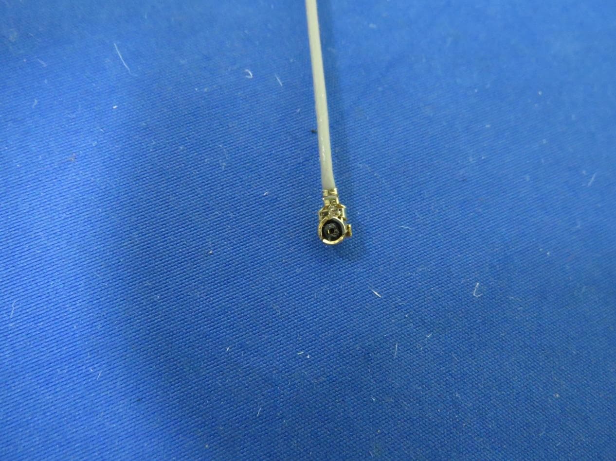
Click to zoom
Application Details
- Equipment Class
- DSC - Part 15 Security/Remote Control Transmitter
- Date of Grant
- May 03, 2023
- Application Purpose
- Original Equipment
- Date of Application
- May 03, 2023
- Equipment Note
- Control Panel
- Frequency Range
- 433.92000000 - 433.92000000
- Company
- Vital Home Systems LLC
- Country
- United States
Documents & Files
Document Text
Text extracted from the exhibit documents filed with the FCC. Open a document above to read the original.
Users Manual
AWSAM-CP Installation and Setup The Best in Property Damage Detection CAUTION! STOP AND READ THIS! IMPORTANT NOTICE TO USER: The installation of any water detection or automatic water shut off system does NOT guarantee water will be detected on all occasions or circumstances. Due to the variety of environments the system can be installed, how it is maintained and types of installation, Vital Command does NOT guarantee or warrant against water or property damage or appliance damage as a result of use of this system. By installing the Vital Command AWSAM System you agree and consent to all of Vital Command’s User Agreements and Terms and Conditions for use of the system and agree that Vital Command is not liable for any type of damage to your person or property. If you do not agree, do not install the system and contact Vital Command. READ THIS ENTIRE MANUAL BEFORE BEGINNING INSTALLATION! Page 1 Always check https://supportawsamcloud.com for the most up to date manual and product info or scan with your mobile device here: AWSAM System Main Features: • Wirelessly monitor buildings for water, temperature, humidity and intrusion while controlling water shut off valves and detect possible conditions that may cause damage. • Wirelessly control and manage the environmental, security and water sensors as well as the control valves that are paired with the AWSAM-CP via any mobile device or computer Online. • Setup, manage and notify system users via text, email or phone alerts of alarms and system operation. • Add and manage devices and sensors with the AWSAM System Page 2 • Perform range tests for device and control panel placement. • Change system settings such as create unique usernames for devices and control panels, set environmental temperature alarm bands, set sensors linking to specific valves. • Monitor system operations and perform automated maintenance on the valve controller. • In the event of a power loss to the system, the AWSAM-CP will operate for a approximately 24 hours on backup battery based on usage. The VC100 Valve Controller will also operate on AC or internal batteries if the batteries have a charge. Page 3 AWSAM Control Panel Cellular Antennas Sensor and Device Antenna Cell Signal Strength Bars Power Light • Green - AC Power and Battery Switch On • Red - No AC or Battery Switch Off Mode light • Brief Blinking - Range Test Mode • Long Blinking- Add Devices Mode Page 4 Back of Control Panel Cellular Antenna Connections Mounting Bracket Holes Wireless Device Antenna Connection Any Position Power Cable Channel Power Jack Connection IMEI Number The last 5 of this number can be used to identify your panel in the AWSAMCloud even if the name is changed IMEI: XXXXXXXXXX Page 5 Right Side of Control Panel Battery Switch • Slide Up - Back up battery is ON • Slide Down - Back up battery is OFF Add Devices and Range Test Button Operation: • A simple button push turns on range test mode. Push once again to turn off. • A 5 second button hold will turn on Add Device mode. This will time out to OFF after 20 minutes if no device button is pushed or push the button once to turn off. • If Range or Add Device Mode is on, any button press turns the OFF the active mode. Page 6 Cellular Connection The AWSAM-CP will attempt to connect to the available cell network once powered on by battery or AC power or both. Once connected, the AWSAM-CP signal bars will light green based on the cell signal received. The smallest signal bar will light with a signal of -111 to -119 dBm or greater. As the cell signal improves additional bars will light green. Wait until you have at least one cell signal light green before operating the control panel. More than one is better. Control Panel Placement The control Panel may be placed in any location that provides AC power a Cell Signal connection and a range test has been completed to the farthest sensor from the control panel. If you are having issues connecting to all three, please troubleshoot on the AWSAMCloud.com website on the “Support” tab click “Troubleshooting”. Panel Mounting Positions Secure the Mounting Bracket to the wall in a vertical or horizontal position first. Then hang the Panel on the bracket. Page 7 Range Test Mode Press and release the button on the side of the panel to enter Range Test mode. Range Test Mode can also be switched ON or OFF in the AWSAMCloud specific Panel settings page. The Mode can be verified by the blinking “Mode Light” on the front of the Panel. In Range test the light will blink briefly. Using either a TWS, or HTWS, or VC100, with the sensor/device battery installed, press the pairing button on the device. Sensor Range Test or Pairing Button location. VC100 button is the red button on the bottom. In Range Test Mode the sensor will beep and respond with an acknowledgment of multiple beeps. This means the sensor is usually responding to the Panel at that location at that moment. If there is a delay after the first beep to get the multiple beeps, the sensor is at the edge of the range and either the sensor or the panel should be moved to accommodate a better wireless connection. If after pushing the button on the sensor and there is no secondary beeps either the sensor is out of range of the panel or the Panel is out of Range Test Mode. You cannot Range Test with the AWS or Door sensors using this mode. You can range test with these sensors by causing an alarm and seeing if you get the alert from the panel. To turn off range test mode press and release the button once. If there are no button pushes in 20 minutes the Panel will time out and turn off Range Test Mode. Page 8 Add Device Mode Press and hold the button on the side of the panel for 5 seconds. Note, the Mode light on the front of the panel will be blinking and mostly on. Press and release the sensor button inside the case. (See pic above) If the Panel is turned on and in range the TWS, HTWS and VC100 will all respond with multiple beeps. The AWS and Door Sensors will onl…
Text truncated - open the document above for the full version.
Attestation Statements
Vital Home Systems LLC RF Declaration Letter 2023-03-30 FEDERAL COMMUNICATI ONS COMMISSION Authorization and Evaluat ion Division 7435 Oaklan d Mills Roa d Columbia, MD 21046 Dea r Sir/Madam, We, Vita l Home Systems LLC hereby declare tha t firmwar e was set AWSAM- CP does not u se th e wirel ess frequency bands(GSM850/GSM1900/UMTS Ban d 2/UMT S Band 4/UMT S Ban d 5) In th e Unit ed States . Consequently, th e us er cannot access or alter all th e frequency bands mentione d above. Produc t Name: Contro l Panel Mod el Name: AWSAM- CP FCC ID: 2AD4D-AWSAMCP Sincer ely Yours, Signature: Contact Person: James R McLaughlin Title: President Company Name & Address: Vital Home Systems LLC 4870 Palmetto Woods Dr Naples, FL 34119 United States
Attestation Statements
Vital Home Systems LLC April 13, 2023 To Whom it may concern: Vital Home Systems LLC product AWSAM-CP control panel complies with FCC regulations “BASIC EQUIPMENT AUTHORIZATION GUIDANCE FOR ANTENNAS USED WITH PART 15 INTENTIONAL RADIATORS” specifically section 15.203 section 2.b and 2.c. FCC ID: 2AD4D-AWSAMCP AWSAM-CP Applicability of section 2.b. – 1. While the antennas are external the control panel has an embedded radio. This radio communication is encrypted and will ONLY transmit and connect to its intended host address and disregard all other signals coming from any other source that does not come from the Host. 2. The AWSAM-CP connects via a VPN Network and each panel has a unique identifier and password that is encoded in the panel and the users and administrators do not know or have access to the firmware, passwords or code from the control panel. Nor can the user access the firmware directly or indirectly as it is encrypted, obfuscated and password protected known only to two people at Vital Home Systems, LLC. 3. If any panel is deemed to operate as an unauthorized system, the AWSAM-CP can be remotely shut off and disconnected from a wireless network including the Vital Home Systems, LLC host remotely changing passwords, encryption or the firmware itself. AWSAM-CP applicability of section 2.c. – 1. Vital Home Systems, LLC only sells its products via a dealer network who use Vital Home Systems, LLC trained installation technicians to install and service the product. Vital Home Systems, LLC requires all of its product to be professionally installed by trained technicians and does not offer installation training to end users or consumers. Vital Home Systems, LLC does not market directly to consumers with the ability to purchase online or self-install. 2. Vital Home Systems, LLC ONLY allows the use of the supplied antennas with the AWSAM- CP. Indication of use of unauthorized antennas WILL result in the immediate shutdown of the systems and void of any warranty Vital Home Systems, LLC may offer. Vital Home Systems, LLC may cancel any dealer agreements and require any outstanding invoices or agreements paid in full for any use of non-authorized attachments, antennas or accessories not provided by Vital Vital Home Systems LLC Home Systems, LLC. 3. Vital Home Systems, LLC does not offer its products for sale directly to end users or on the internet to consumers. It only offers its products via a national or regional dealer network with professional installation technicians who must have gone through a Vital Home Systems, LLC installation training, or participate in trainer certifications and train their installers using only Vital Home Systems, LLC supplied materials. 4. Vital Home Systems, LLC’s sales and installation process requires dealers to name their installers and provide them specific access to the Host to set up any Vital Home Systems, LLC system prior to installation and Vital Home Systems, LLC does not allow or send end users access directly to the host. Access to the end user is only provided by the dealer and installer once the system has been physically installed by a technician. 5. Installation Technicians and the dealer networks are the only ones trained in how to access the systems to install them, install the Antennas, activate the system to communicate with the host, conduct range tests and field strength tests. 6. Vital Home Systems, LLC will only activate a cellular connection and electronically assign a AWSAM-CP to a dealer with trained installation technicians. Please contact Jim McLaughlin with Vital Home Systems, LLC if you have any questions. Sincerely, Contact Person: James R McLaughlin Title: President Company Name & Address: Vital Home Systems LLC 4870 Palmetto Woods Dr Naples, FL 34119 United States
Attestation Statements
Vital Home Systems LLC CFR 47 §2.911(d)(5)(i) Attestation Letter Attestation Letter Date: 2023-03-30 FEDERAL COMMUNICATIONS COMMISSIONS Authorization and Evaluation Division 7435 Oakland Mills Road Columbia, MD 21046 Ref: Attestation Statements CFR 47 §2.911(d)(5)(i)(ii) Filing FCC ID:2AD4D-AWSAMCP Vital Home Systems LLC (“the applicant”) certifies that the equipment for which authorization is sought is not “covered” equipment prohibited from receiving an equipment authorization pursuant to section 2.903 of the FCC rules. Vital Home Systems LLC (“the applicant”) certifies that as of the date of the filing of the application, the applicant is not identified on the Covered List as an entity producing “covered” equipment. Sincerely, Contact Person: James R McLaughlin Title: President Company Name & Address: Vital Home Systems LLC 4870 Palmetto Woods Dr Naples, FL 34119 United States
Attestation Statements
Vital Home Systems LLC Attestation Letter for Agent Date: 2023-03-30 FEDERAL COMMUNICATIONS COMMISSIONS Authorization and Evaluation Division 7435 Oakland Mills Road Columbia, MD 21046 Ref: Attestation Statements Part 2.911 (d)(7) Filing FCC ID:2AD4D-AWSAMCP Vital Home Systems LLC certifies that, as of the date of the filing of the application, Vital Home Systems LLC is our designated U.S. agent for service of process for the above referenced FCC ID: 2AD4D-AWSAMCP. Vital Home Systems LLC agrees to maintain an agent for no less than one year after the grantee has terminated all marketing and importation or the conclusion of any Commission-related proceeding involving the equipment. Vital Home Systems LLC accepts, as of the date of the filing of the application, the obligation of the designated U.S. agent for service of process for the above referenced FCC ID. Designated U.S. Agent Information: Company name: Vital Home Systems LLC Address: 4870 Palmetto Woods Dr, Naples FL 34119 FRN: 0024244931 Contact person: James R McLaughlin Tel: (619) 788-1821 Email: [email protected] Sincerely yours, Applicant Agent Signature Contact Person: James R McLaughlin Title: President Signature Contact Person: James R McLaughlin Title: President
Cover Letter(s)
Vital Home Systems LLC FCC Confidential Authorization 2021-09-22 FEDERAL COMMUNICATIONS COMMISSIONS Authorization and Evaluation Division 7435 Oakland Mills Road Columbia, MD 21046 Subject: Confidentiality Request regarding application for certification of FCC ID: 2AD4D-AWSAMCP In accordance with Sections 0.457 and 0.459 of the Commission’s Rules, Vital Home Systems LLC. Doing business as Vital Command hereby requests long-term confidential treatment of information accompanying this application as outlined below: •Block Diagram •Schematics •Operation Description The above materials contain proprietary and confidential information not customarily released to the public. The public disclosure of these materials provides unjustified benefits to its competitors in the market. Sincerely, Signature: Contact Person: James R McLaughlin Title: President Company Name & Address: Vital Home Systems LLC 4870 Palmetto Woods Dr Naples, FL 34119 United States QA-FR-171-A
Cover Letter(s)
Vital Home Systems LLC 7/29/2014 FCC Authorization 2023 -03-30 FEDERAL COMMUNICATIONS COMMISSIONS Authorization and Evaluation Division 7435 Oakland Mills Road Columbia, MD 21046 Subject: Agent Authorization To whom it may concern: We Vital Home Systems LLC the undersigned, Hereby authorizes Bay Area Compliance Laboratories Corporation (Linkou) to act on its behalf in all matters relating to application for Equipment authorization, including the signing of all documents relating to these matters. All acts carried out by Bay Area Compliance Laboratory Corporation (Linkou) on our behalf shall have the same effect as our own action. We, the undersigned, hereby certify that we are not subject to a denial of federal benefits, that includes FCC benefits, pursuant to Section 5301 of the Anti-Drug Abuse Act of 1988, 21 U.S.C. 862. This authorization is valid until further written notice from the applicant. Sincerely Yours, Signature: Contact Person: James R McLaughlin Title: President Company Name & Address: Vital Home Systems LLC 4870 Palmetto Woods Dr Naples, FL 34119 United States
External Photos
Bay Area Compliance Laboratories Corp.(Linkou Laboratory) Project No.: RLK210218005-TR Page 1 of 12 External Photographs (Brand: Vital Home Systems / Model: AWSAM-CP ) Bay Area Compliance Laboratories Corp.(Linkou Laboratory) Project No.: RLK210218005-TR Page 2 of 12 Bay Area Compliance Laboratories Corp.(Linkou Laboratory) Project No.: RLK210218005-TR Page 3 of 12 Adapter Bay Area Compliance Laboratories Corp.(Linkou Laboratory) Project No.: RLK210218005-TR Page 4 of 12 Bay Area Compliance Laboratories Corp.(Linkou Laboratory) Project No.: RLK210218005-TR Page 5 of 12 Bay Area Compliance Laboratories Corp.(Linkou Laboratory) Project No.: RLK210218005-TR Page 6 of 12 LTE Antenna Bay Area Compliance Laboratories Corp.(Linkou Laboratory) Project No.: RLK210218005-TR Page 7 of 12 Bay Area Compliance Laboratories Corp.(Linkou Laboratory) Project No.: RLK210218005-TR Page 8 of 12 Bay Area Compliance Laboratories Corp.(Linkou Laboratory) Project No.: RLK210218005-TR Page 9 of 12 SDR Antenna Bay Area Compliance Laboratories Corp.(Linkou Laboratory) Project No.: RLK210218005-TR Page 10 of 12 Bay Area Compliance Laboratories Corp.(Linkou Laboratory) Project No.: RLK210218005-TR Page 11 of 12 Bay Area Compliance Laboratories Corp.(Linkou Laboratory) Project No.: RLK210218005-TR Page 12 of 12
Internal Photos
Bay Area Compliance Laboratories Corp.(Linkou Laboratory) Project No.: RLK210218005-TR Page 1 of 19 Internal Photographs (Brand: Vital Home Systems / Model: AWSAM-CP ) Bay Area Compliance Laboratories Corp.(Linkou Laboratory) Project No.: RLK210218005-TR Page 2 of 19 Bay Area Compliance Laboratories Corp.(Linkou Laboratory) Project No.: RLK210218005-TR Page 3 of 19 Bay Area Compliance Laboratories Corp.(Linkou Laboratory) Project No.: RLK210218005-TR Page 4 of 19 Bay Area Compliance Laboratories Corp.(Linkou Laboratory) Project No.: RLK210218005-TR Page 5 of 19 Bay Area Compliance Laboratories Corp.(Linkou Laboratory) Project No.: RLK210218005-TR Page 6 of 19 Bay Area Compliance Laboratories Corp.(Linkou Laboratory) Project No.: RLK210218005-TR Page 7 of 19 Bay Area Compliance Laboratories Corp.(Linkou Laboratory) Project No.: RLK210218005-TR Page 8 of 19 Bay Area Compliance Laboratories Corp.(Linkou Laboratory) Project No.: RLK210218005-TR Page 9 of 19 Bay Area Compliance Laboratories Corp.(Linkou Laboratory) Project No.: RLK210218005-TR Page 10 of 19 Bay Area Compliance Laboratories Corp.(Linkou Laboratory) Project No.: RLK210218005-TR Page 11 of 19 Bay Area Compliance Laboratories Corp.(Linkou Laboratory) Project No.: RLK210218005-TR Page 12 of 19 Bay Area Compliance Laboratories Corp.(Linkou Laboratory) Project No.: RLK210218005-TR Page 13 of 19 Bay Area Compliance Laboratories Corp.(Linkou Laboratory) Project No.: RLK210218005-TR Page 14 of 19 Bay Area Compliance Laboratories Corp.(Linkou Laboratory) Project No.: RLK210218005-TR Page 15 of 19 Bay Area Compliance Laboratories Corp.(Linkou Laboratory) Project No.: RLK210218005-TR Page 16 of 19 Bay Area Compliance Laboratories Corp.(Linkou Laboratory) Project No.: RLK210218005-TR Page 17 of 19 Battery Bay Area Compliance Laboratories Corp.(Linkou Laboratory) Project No.: RLK210218005-TR Page 18 of 19 Bay Area Compliance Laboratories Corp.(Linkou Laboratory) Project No.: RLK210218005-TR Page 19 of 19
RF Exposure Info
RF EXPOSURE TEST REPORT For Vital Home Systems LLC 4870 Palmetto Woods Dr Naples, FL 34119 United States Report Type Original Report FCC Identity: FCC ID: 2AD4D-AWSAMCP Brand Name Vital Home Systems Product Name Control Panel Model Name AWSAM-CP Report Number RLK210218005-MPE Report Date 2021/11/19 Reviewed By Danny Sung Prepared By: Bay Area Compliance Laboratories Corp. (Linkou Lab) No. 6, Wende 2Rd., Guishan Dist., Taoyuan City 33382, Taiwan (R.O.C.) Tel: +886 (3)3961072; Fax: +886 (3) 3961027 www.bacl.com.tw Note: This test report is prepared for the customer shown above and for the device described herein. It may not be duplicated or used in part without prior written consent from Bay Area Compliance Laboratories Corp. (Linkou Lab) Bay Area Compliance Laboratories Corp. (Linkou Lab) Report No.: RLK210218005-MPE Page 2 of 8 Revision History Revision Report Number Issue Date Description 1.0 RLK210218005-MPE 2021/11/19 Original Report Bay Area Compliance Laboratories Corp. (Linkou Lab) Report No.: RLK210218005-MPE Page 3 of 8 TABLE OF CONTENTS 1 GENERAL INFORMATION ...................................................................................................................................... 4 1.1 PRODUCT DESCRIPTION FOR EQUIPMENT UNDER TEST (EUT) .................................................................................... 4 1.2 OPERATION CONDITION OF EUT .......................................................................................................................... 5 1.3 OBJECTIVE ........................................................................................................................................................ 5 1.4 TEST METHODOLOGY ......................................................................................................................................... 5 1.5 TEST FACILITY ................................................................................................................................................... 5 2 SUMMARY OF TEST RESULTS ............................................................................................................................... 6 3 FCC §1.1310 – MAXIMUM PERMISSIBLE EXPOSURE (MPE)................................................................................. 7 3.1 APPLICABLE STANDARD ....................................................................................................................................... 7 3.2 RF EXPOSURE EVALUATION RESULT ...................................................................................................................... 8 Bay Area Compliance Laboratories Corp. (Linkou Lab) Report No.: RLK210218005-MPE Page 4 of 8 1 General Information 1.1 Product Description for Equipment under Test (EUT) Applicant Vital Home Systems LLC 4870 Palmetto Woods Dr Naples, FL 34119 United States Manufacturer Nutek Corporation No. 167, Lane 235, Bauchiau Rd., Xindian District, New Taipei City 23145, Taiwan Brand(Trade) Name Vital Home Systems Product (Equipment) Control Panel Model Name AWSAM-CP Frequency Range LTE Band 2: 1850-1910 MHz(TX), 1930-1990MHz(RX) LTE Band 4: 1710-1755 MHz(TX), 2110-2155MHz(RX) LTE Band 5: 824-849 MHz(TX), 869-894 MHz(RX) LTE Band 7: 2500-2570 MHz(TX), 2620-2690 MHz(RX) LTE Band 12: 699-716 MHz(TX), 729-746 MHz(RX) LTE Band 18: 815-830 MHz(TX), 860-875 MHz(RX) LTE Band 19: 830-845 MHz(TX), 875-890 MHz(RX) SRD: 433.92MHz Modulation Type LTE: QPSK,16QAM SRD: ASK Antenna Type Dipole Antenna Maximum Antenna Gain LTE Band 2: 5.43 dBi LTE Band 4: 5.48 dBi LTE Band 5: -1.3 dBi LTE Band 7: 3.13 dBi LTE Band 12: -0.88 dBi LTE Band 18: -1.3 dBi LTE Band 19: -1.3 dBi Received Date Mar. 11, 2021 Date of Test Mar. 15, 2021 ~ Sep. 07, 2021 Note: All measurement test data in this report was gathered from original report: I17D00184-MPE01 (FCC ID: QIPPLS62-W) Bay Area Compliance Laboratories Corp. (Linkou Lab) Report No.: RLK210218005-MPE Page 5 of 8 1.2 Operation Condition of EUT Power Operation (Voltage Range) AC 120V/60Hz Adapter Brand Name: Xing Yuan Electronics Co., Ltd Model: XY12J-0502000Q-UW I/P: 100-240VAC,0.5A Max 50/60Hz O/P: 5Vdc, 2.0A. By Power Core DC Type DC Power Supply Battery External from USB Cable External DC Adapter Host System 1.3 Objective The Objective of this Test Report was to document the compliance of the Vital Home Systems LLC. Appliance (Model: AWSAM-CP) to the requirements of the following Standards: - FCC Part 1 (§1.1310)、Part 2 (§2.1091) 1.4 Test Methodology All measurements indicated in this document were performed in accordance with the Code of Federal Regulations Title 47 Part 2 as the following parts: Part 2 (§2.1091) KDB 447498 D01 General RF Exposure Guidance v06 1.5 Test Facility The Test site used by Bay Area Compliance Laboratories Corp.(Linkou Lab) to collect test data is located on No.6, Wende 2Rd., Guishan Dist., Taoyuan City 33382, Taiwan (R.O.C.) Bay Area Compliance Laboratories Corp.(Linkou Lab) Lab is accredited to ISO 17025 by Taiwan Accreditation Foundation (TAF code: 3546) and the FCC designation No.TW3546 under the Mutual Recognition Agreement (MRA) in FCC Test. The facility also complies with the radiated and AC line conducted test site criteria set forth in ANSI C63.10. The Federal Communications Commission has the reports on file and is listed under FCC Registration No.: 974454. The test site has been approved by the FCC for public use and is listed in the FCC Public Access Link (PAL) database. Bay Area Compliance Laboratories Corp. (Linkou Lab) Report No.: RLK210218005-MPE Page 6 of 8 2 Summary of Test Results FCC Rules Description of Test Result §1.1310 Maximum Permissible Exposure (MPE) Compliance Bay Area Compliance Laboratories Corp. (Linkou Lab) Report No.: RLK210218005-MPE Page 7 of 8 3 FCC §1.1310 – Maximum Permissible Exposure (MPE) 3.1 Applicable Standard According to subpart §1.1310, systems operating under the provisions of this section shall be operated in a manner that ensure…
Text truncated - open the document above for the full version.
Test Report
Page 1 of 21 FCC Part 15.231 TEST REPORT For Vital Home Systems LLC 4870 Palmetto Woods Dr Naples, FL 34119 United States FCC ID: 2AD4D-AWSAMCP Report Type Original Report Product Name: Control Panel Model Name: AWSAM-CP Report Number : RLK210218005 Report Date : 2021/10/01 Reviewed By: Ethan Shao Prepared By: Bay Area Compliance Laboratories Corp. (Linkou Lab) No. 6, Wende 2Rd., Guishan Dist., Taoyuan City 33382, Taiwan (R.O.C.) Tel: +886 (3)3961072; Fax: +886 (3) 3961027 www.bacl.com.tw Note: This test report is prepared for the customer shown above and for the device described herein. It may not be duplicated or used in part without prior written consent from Bay Area Compliance Laboratories Corp. (Linkou Lab) Bay Area Compliance Laboratories Corp. (Linkou Lab) Report No.: RLK210218005 Page 2 of 21 Revision History Revision Report Number Issue Date Description 1.0 RLK210218005 2021/10/01 Original Report Bay Area Compliance Laboratories Corp. (Linkou Lab) Report No.: RLK210218005 Page 3 of 21 TABLE OF CONTENTS 1 General Information ................................................................................................................. 4 1.1 Product Description for Equipment under Test (EUT) .................................................. 4 1.2 Operation Condition of EUT .............................................................................................. 4 1.3 Objective .............................................................................................................................. 4 1.4 Measurement Uncertainty ................................................................................................. 5 1.5 Test Methodology ............................................................................................................... 5 1.6 Test Facility .......................................................................................................................... 5 2 System Test Configuration .................................................................................................... 6 2.1 Description of Test Configuration ..................................................................................... 6 2.2 Equipment Modifications ................................................................................................... 6 2.3 EUT Exercise Software ...................................................................................................... 6 2.4 Block Diagram of Test Setup ............................................................................................ 6 2.5 Environmental Conditions and Test Date ....................................................................... 7 3 Summary of Test Results ....................................................................................................... 8 4 Test Equipment List and Details .......................................................................................... 9 5 FCC §15.203 – Antenna Requirements ............................................................................. 10 5.1 Applicable Standard ......................................................................................................... 10 5.2 Antenna Information ......................................................................................................... 10 6 FCC §15.207 - AC Line Conducted Emissions ................................................................ 11 6.1 Applicable Standard ......................................................................................................... 11 6.2 EUT Setup and Test Procedure ..................................................................................... 11 6.3 Test Equipment List and Details ..................................................................................... 12 6.4 Test Result ......................................................................................................................... 13 7 FCC §15.205, §15.209 , §15.231 (a) - Radiated Emissions ........................................... 14 7.1 Applicable Standard ......................................................................................................... 14 7.2 Measurement Uncertainty ............................................................................................... 15 7.3 EUT Setup ......................................................................................................................... 15 7.4 EMI Test Receiver & Spectrum Analyzer Setup .......................................................... 16 7.5 Test Procedure .................................................................................................................. 16 7.6 Corrected Factor & Margin Calculation ......................................................................... 17 7.7 Test Results Summary ..................................................................................................... 17 7.8 Test Results ....................................................................................................................... 17 8 FCC §15.231(C) – 20 dB Emission Bandwidth ................................................................ 19 8.1 Applicable Standard ......................................................................................................... 19 8.2 Test Procedure .................................................................................................................. 19 8.3 Test Equipment List and Details ..................................................................................... 19 8.4 Test Results ....................................................................................................................... 19 9 FCC §15.231(a) –Deactivation Testing .............................................................................. 20 9.1 Applicable Standard .................................................…
Text truncated - open the document above for the full version.
Contact Information
Applicant
James Mclaughlin(President)
Test Firm
Bay Area Compliance Laboratories Corp.(Linkou Lab)Gimmy Tsai
Technical Specifications
| # | Rule Parts | Frequency Range | Power Output |
|---|---|---|---|
| 1 | 15.231 | 433.92 MHz - 433.92 MHz | - |