2AD4EESL1Remote
Shanghai So-Fun Sports Equipment Co., Ltd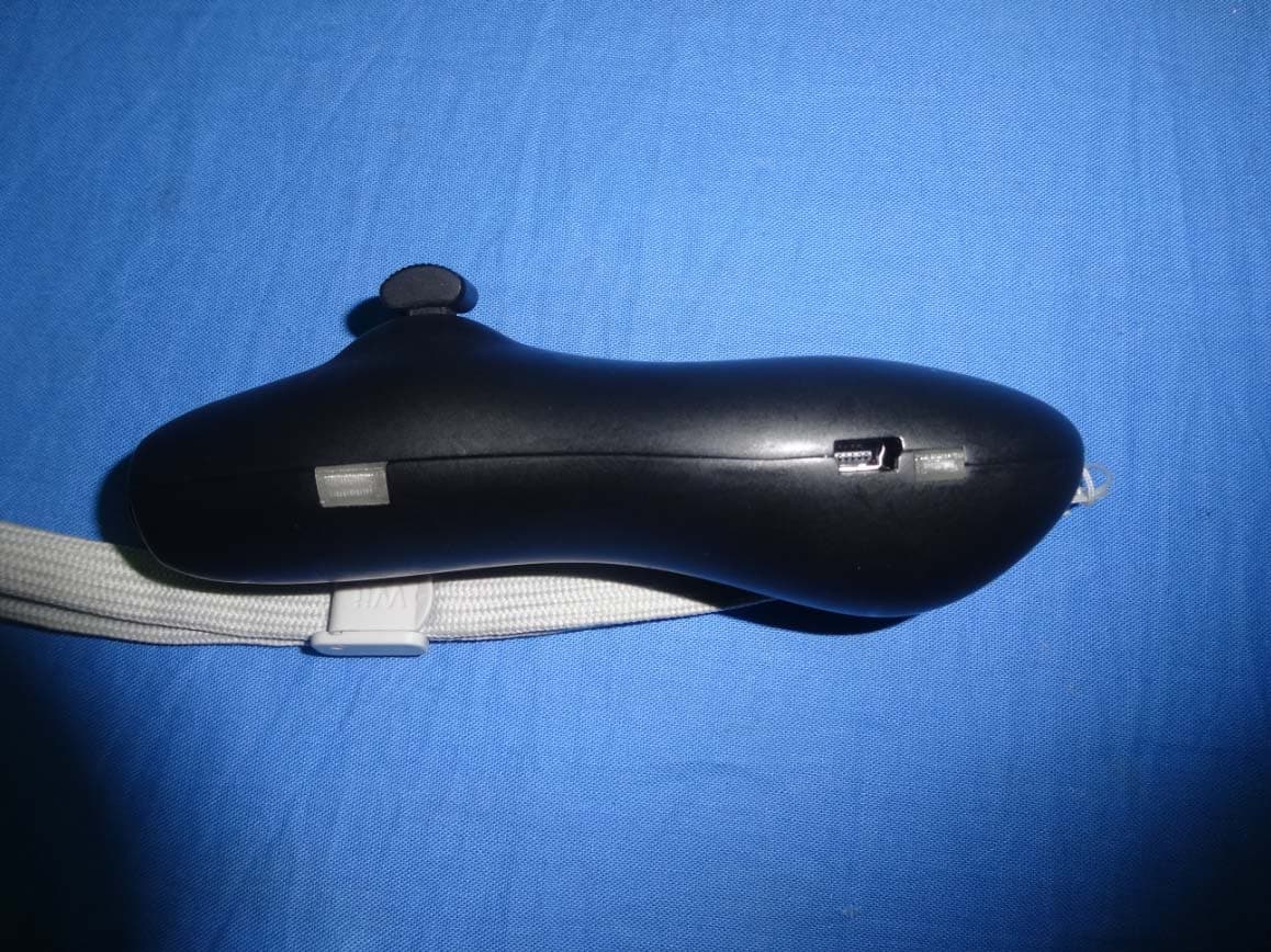
Click to zoom
Application Details
- Equipment Class
- DXX - Part 15 Low Power Communication Device Transmitter
- Date of Grant
- Jan 27, 2015
- Application Purpose
- Original Equipment
- Date of Application
- Jan 27, 2015
- Equipment Note
- Remote
- Frequency Range
- 2402.00000000 - 2480.00000000
- Country
- China
Documents & Files
Document Text
Text extracted from the exhibit documents filed with the FCC. Open a document above to read the original.
Users Manual
1 1 THE CONTROLLER INSTRUCTION 2 THE CONTROLLER A key feature of the Falcon is definitely its sleek, pocket-sized, wireless controller which allows you to intuitively control its movements by simply sliding the throttle / brake up and down. Once the controller and the board is powered on, they will make an auto signal START button / headlight button 1. throttle / brake 2. horn button 3. match. 1. 2. 4. 3. 4. mini USB port 5. 5. board battery indicator 6. controller battery indicator 6. 7. controller charging indicator 7. THE CONTROLLER MAY CONTROL THE BOARD UNDER 2 RIDING MODES: NORMAL MODE - WITH A LIMITED SPEED OF 30KM/H THE CONTROLLER HAS INDICATORS THAT SHOW BOTH THE BOARD AND CONTROLLER BATTERY PERCENTAGE. GREEN, YELLOW, RED LIGHTS INDICATES 100%, 60%, 30% POWER RESERVES. THE CONTROLLER IS DESIGNED ESPICIALLY FOR HUMAN HAND GRIP. WITH MATT FINISHED SURFACE AND ENVIRONMENT FRIENDLY COATED, THE CONTROLLER BRINGS STABLE FEELING IN CONTROLLING THE BOARD. AT JUST 50 GRAMS, THE CONTROLLER IS LIGHTWEIGHT AND PORTABLE WHICH BRINGS ALMOST NO BURDEN TO RIDER TO FULLY CHARGE THE CONTROLLER BATTERY, A 1 HOURS' CHARGE TIME FROM A STANDARD A/C POWER SOURCE IS NEEDED. ANY USB CABLE FOR MOBILE PHONE CAN BE USED FOR CHARGING THE CONTROLLER. FEATURES 2 3 CRUISE CONTROL MODE - WITH A LIMITED SPEED OF 15KM/H ERGO THE CONTROLLER OPERATION Hold button A for 3 seconds to turn on the remote controller. Under working state, hold button A for 3 seconds to turn it off. Once powered ON, the indicator 6 will show controller's battery reserve. Green, yellow, red lights means 100/60/30 percentage of battery reserve. If both the board and controller are powered ON and synchronized, you can control the board now. Push the throttle forward to accelerate and push backward to brake. When going forward, press the throttle to switch into cruise control mode at 15km/h speed. Push the throttle to cancel the cruise mode. 1.2 1.1 2.1 2.2 3.1 POWER SWITCH Charge the controller with the USB cable. During charging, indicator 7 will give red light. When fully charged, the red light will turn to green. 5.1 HEADLIGHT / HORN RIDING CONTROL CONTROLLER POWER INDICATOR 2.3 When powered ON and rest, press the throttle to lock the controller, and press again to unlock. BOARD POWER INDICATOR Once powered ON, the indicator 5 will show board's battery reserve. Green, yellow, red lights means 100/60/30 percentage of battery reserve. 4.1 If both the board and controller are powered ON and synchronized, press button A to turn on the headlight and press button B to blow the horn. CHARGING 4 5 SPECFICATIONS BOARD CONTROL High Speed Mode Max.: 18.6mph / 30km/h Cruise Control Mode Max.: 12.4mph / 20km/h CHARGER Input: DC 5V / 500mA Max. Charge Indicator: Red when charging / Green when charged CONTROLLER Material: ABS Plastic Dimensions: 125*41*33mm Weight: 40g Battery Type: Lithium Battery Capacity: 240mAH Battery Charging Time: 60 minutes Wireless Connection: 2.4GHz Synchronizing time: 3 seconds THE USB Use the USB to connect the wireless controller to any computer or any other USB port for recharging purposes. Remote control distance: 10 meters SYNCING CONTROLLER AND BOARD 6 Every Falcon Cruiser is connected with its controller through a unique radio frequency. You will hear beep sounds after turning on the Falcon Cruise and its controller. The matching is completed when the beep finished. 7 TROUBLESHOOTING Check if the controller is activated on. When turned on, the indicator should give green/yellow/red lights, indicating different power reserve. Check if the board is powered ON. When turning ON the controller, it will show the power remains of the board, then check if there is power left. If both the board and controller are powered ON, check if the synchronizing is completed. A beep sound indicates that the matching is finished. If the controller got wet, dry the surface immediately. If the water get inside the controller, shut down the controller and put in a dry place. If the controller get crashed or cracked, check if the controller still works, Local dealer will change a new controller case for damaged one. 1.2 1.1 1.3 2.1 2.2 MY CONTROLLER DOESN`T CONTROL THE BOARD Check if the controller is connected correctly with USB cable to power resource, incorrect voltage may cause faliure in charging. For the malfunction, please do not repair by yourself, and ask local dealer for tech help. 2.1 2.2 MY CONTROLLER DOESN'T CHARGE MY CONTROLLER GOT DAMAGED 8 ABOUT THE SAFETY GUIDELINES BEFORE RIDING THE FALCON, IT IS STRONGLY ADVISED TO READ THROUGH AND FOLLOW ALL TIPS, INSTRUCTIONS AND WARNINGS LISTED UNDERNEATH. THIS CAN REDUCE THE RISKS THAT COMES WITH USING A PERSONAL ELECTRONIC TRANSPORTER (PET) // IT SHOULD BE CLEAR THAT READING THIS MANUAL WILL ONLY REDUCE AND NOT ELIMINATE THE RISK INHERENT TO USING A PERSON- AL ELECTRIC TRANSPORT (PET) // IF YOU EXCEED THE ABILITY OF YOURSELF OR YOUR CRUISER BY RIDING OVER OBSTACLES OR OTHER UNSUITABLE SURFACES, THIS MIGHT POTENTIALLY LEAD TO COLLISIONS OR FALLS THAT MAY CAUSE SERIOUS OR FATAL INJURY, OR THE DAMAGING OF YOUR FALCON CRUISER. NEW RIDERS FIRST TIME USING A FALCON? START BY RIDING IN THE LOW SPEED MODE // INEXPERIENCED RIDERS ARE BEST TO FIRST PRACTICE IN A SPACIOUS, NON TRAFFIC ZONE // PUSH THE THROTTLE SLOWLY TO ACCELERATE AND BRAKE SLOWLY // A SUDDEN PUSH TO THROTTLE MAY CAUSE YOU LOOSE BALANCE // A SUDDEN AND STRONG BRAKE MAY CAU YOU LOOSE BALANCE // USE HEADLIGHT AND HORN TO WARN OTHERS ON STREET BY PRESSING BUTTON A AND B // WHEN THE CONTROLLER IS POWERED ON AND IN REST, PRESS THE SAFETY WARNINGS AND TIPS THROTTLE TO LOCK IT TO AVOID ACTIVATE THE BOARD ACCIDENTALY // WHEN THE BOARD POWER RESERVE IS LOW, SWITCH TO CRUISE CONTROL MODE BY PRESSING THE THROTTLE DURING CRUISING 9 BATTERY SAFETY LITHIUM-ION BATTERIES CAN EXPLODE OR CAUSE A FIRE IF THEY ARE USED INCORRECTLY OR IF THEY ARE DEFECTIVE. THEREFORE, YOU ARE RECOMMENDED TO READ THE FOLLOWING INSTRUCTIONS VERY CAREFULLY: - EACH TIME B…
Text truncated - open the document above for the full version.
ID Label/Location Info
FCC ID: 2AD4EESL1 FCC ID LABEL: Label size: L*W=15*5mm FCC ID: 2AD4EESL1
Test Report
The results detailed in this test report relate only to the specific sample(s) tested. It is the Application’s responsibility to ensure that all production units are manufactured with equivalent EMC characteristics. This report is not to be reproduced except in full, without written approval from Shenzhen POCE Technology Co., Ltd.. FCC ID TEST REPORT Prepared for...............................: Shanghai So-Fun Sports Equipment Co., Ltd Address.....................................: Room 208, No. 1, Lane 881, Mingzhong Road, Songjiang District, Shanghai, China Equipment Under Test(E.U.T.): Electric Skateboard (Remote) Model.........................................: ESL1 FCC ID......................................: 2AD4EESL1 Applicable Standards........................: FCC CFR Title 47 Part 15 Subpart C Section 15.249:2013 Test Date...................................: 05 January 2015 to 26 January 2015 Issued Date...............................: 27 January 2015 Report Number.........................: POCE14121733JRF Test Engineer............................: Reviewed By.............................: Prepared By...............................: Shenzhen POCE Technology Co., Ltd. H Building, Hongfa Science and Technology Park, Tangtou, Shiyan, Bao’an District, Shenzhen, China Tel: 86-755-2911 3252 Fax: 86-755-2911 3135 Shenzhen POCE Technology Co., Ltd. Report No.: POCE14121733JRF FCC ID: 2AD4EESL1 H Building, Hongfa science and Technology Park, Tangtou, Shiyan, Bao’an District, Shenzhen, China Tel: +86-755-2911 3252 Fax: +86-755-2911 3135 http://www. poce-cert.com Page 2 of 21 Table of Contents 1.0 General Information.......................................................................................................................................... 3 1.1 Client Details ............................................................................................................................................... 3 1.2 Test Lab Details ........................................................................................................................................... 3 1.3 Description of E.U.T. ................................................................................................................................... 4 1.4 AE used during the test ................................................................................................................................ 4 2.0 Test Summary.................................................................................................................................................... 5 3.0 E.U.T. Modification........................................................................................................................................... 5 4.0 Measurement Uncertainty................................................................................................................................5 5.0 Antenna Requirement....................................................................................................................................... 6 5.1 Applicable Standard..................................................................................................................................... 6 5.2 Antenna Specification .................................................................................................................................. 6 6.0 Power Line Conducted Emission Test.............................................................................................................. 7 6.1 Test Equipment ............................................................................................................................................ 7 6.2 Test Method and test Procedure ................................................................................................................... 7 6.3 E.U.T. Operating Condition ......................................................................................................................... 7 6.4 Power line conducted Emission Limit according to Paragraph 15.207 ....................................................... 7 6.5 Test specification: ........................................................................................................................................ 7 6.6 Test Result: .................................................................................................................................................. 7 7.0 Radiated Emission Test................................................................................................................................... 10 7.1 Test Equipment .......................................................................................................................................... 10 7.2 Test Method and test Procedure:................................................................................................................ 10 7.3 Block diagram of test setup ....................................................................................................................... 10 7.4 E.U.T. Operating Condition ....................................................................................................................... 11 7.5 Radiated Emission Limit ........................................................................................................................... 12 7.6 Test specification: ...................................................................................................................................... 12 7.7 Test result................................................................................................................................................... 12 8.0 Band Edge........................................................................................................................................................ 18 8.1 Test Equipment .......................................................................…
Text truncated - open the document above for the full version.
Contact Information
Applicant
Yuan Ji(Manager)
Technical Contact
Shenzhen POCE Technology Co., LtdJack Kang
[email protected](86)75529113252
Room 502, No. 1, Xinghua Garden · Shenzhen · China
Test Firm
Shenzhen POCE Technology Co.,Ltd.Bill Yuan
Technical Specifications
| # | Rule Parts | Frequency Range | Power Output |
|---|---|---|---|
| 1 | 15C | 2.40 GHz - 2.48 GHz | - |