2AD7W-6543891Wireless Transmission System (WTS)
Sirona Dental Systems GmbH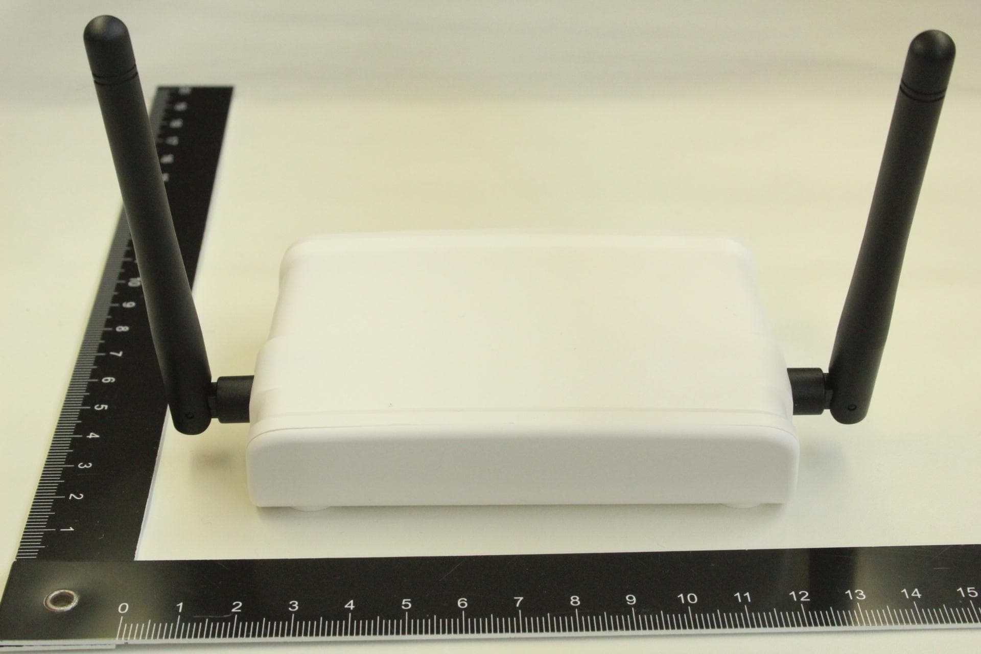
Click to zoom
Application Details
- Equipment Class
- DTS - Digital Transmission System
- Date of Grant
- Mar 18, 2015
- Application Purpose
- Original Equipment
- Date of Application
- Mar 17, 2015
- Equipment Note
- Wireless Transmission System (WTS)
- Frequency Range
- 2402.00000000 - 2480.00000000
- Company
- Sirona Dental Systems GmbH
- Country
- Germany
Documents & Files
Document Text
Text extracted from the exhibit documents filed with the FCC. Open a document above to read the original.
Users Manual
1/33 CEREC Radio Device Operating Manual This document contains a functional and operational manual for the CEREC Radio Device which implements a wireless network to be used for the communication between acquisition units and milling units in the CEREC system. 2/33 Table of contents 1. Introduction 1.1 Important User Information 1.2 FCC and IC Declarations 2. Product Description 2.1 Operational Elements 2.2 LED Indications 3. Specification 4. System description 4.1 CEREC system 4.2 System components 4.3 Main function 4.4 Network unit 5. Networking 5.1 CEREC Radio Device network overview 5.2 Creating a network 5.2.1 Creation 5.2.2 Isolated network unit 5.2.3 Persistent network 5.2.4 Installation 5.2.5 Maximum size 5.3 Network creation failures 5.3.1 Isolated network unit 5.3.2 Multiple networks created 5.4 Extending the network 5.4.1 Add new network unit 5.4.2 Reduce network 5.5 Increasing network coverage 5.5.1 LAN cable extension 5.5.2 Connecting to Ethernet infrastructure 5.6 Reset to factory defaults 5.7 Network unit states 5.7.1 States definitions 5.7.2 State transitions 5.7.3 LED indications 5.8 Radio characteristics 5.8.1 Frequency spectrum 5.8.2 Channel control 5.8.3 Channel switching 6. Use cases 6.1 Moving around 6.1.1 Moving within network 6.1.2 Temporarily disconnected 6.1.3 Disconnected 6.2 Transmit data wirelessly 6.2.1 Stationary data transmission 6.2.2 Network routing 3/33 6.2.3 Multiple streams 6.3 Transmit data using LAN 6.3.1 LAN routing 6.3.2 Handover 6.3.3 Simultaneous access 6.4 Interrupted transmission 4/33 1. Introduction Thank you for choosing Sirona CEREC Radio Device. CEREC Radio Device (part no. 6543891 D3492) is a powerful 100 Base-T Ethernet wireless transmission system that allows peripheral devices to build up a wireless network or to access a wired network. The CEREC Radio Device operates in the 2.4 GHz ISM band and complies with FCC, IC and EC regulations. CEREC Radio Device is easy to install and does not require specific drivers. It can be used with most computers and operating systems. This manual includes the device’s technical data and operating instructions. In case of problems during the installation or during the operation that cannot be solved with the information given in this manual, please contact the service department of your local dealer or contact: In the USA: Sirona Dental Systems GmbH Sirona Dental Systems LLC Fabrikstrasse 31 4835 Sirona Drive, Suite 100 D-64625 Bensheim Charlotte, NC 28273 Germany USA www.sirona.com 1.1 Important User Information CEREC Radio Device (part no. 6543891 D3492) does not require maintenance work or special attendance except for the following instructions outlined below. CAUTION: Do not operate the device within the range of strong electromagnetic fields. Comply with the temperature range for operation mentioned in chapter Technical Data. Avoid overheating. Protect device against humidity and dust. Clean device only with a soft cloth and mild cleaning agent. Do not apply water or wet cleaner. Do not insert any objects into device openings unless specifically mentioned otherwise in this document. This may damage the device. 5/33 Do not open the CEREC Radio Device. The CEREC Radio Device does not contain parts which could be maintained, exchanged or repaired by the customer or non-authorized maintenance personnel. Opening the device can damage the electric components. A correctly functioning device is no longer guaranteed! 1.2 FCC and IC Declarations Compliance statement This device complies with part 15 of the FCC Rules and to Industry Canada’s license-exempt RSSs. Operation is subject to the following two conditions: (1) this device may not cause harmful interference, and (2) this device must accept any interference received, including interference that may cause undesired operation. Warning Changes or modifications not expressly approved by the party responsible for compliance could void the user’s authority to operate the equipment. This in particular is applicable for the antenna which has been delivered with the CEREC Radio Device. RF Exposure To comply with FCC RF exposure requirements for mobile transmitting devices, this transmitter should only be used or installed at locations where there is at least 20cm separation distance between the antenna and all persons. Information to the User Note: This equipment has been tested and found to comply with the limits for a Class B digital device, pursuant to part 15 of the FCC Rules. These limits are designed to provide reasonable protection against harmful interference in a residential installation. This equipment generates, uses and can radiate radio frequency energy and, if not installed and used in accordance with the instructions, may cause harmful interference to radio communications. However, there is no guarantee that interference will not occur in a particular installation. If this equipment does cause harmful interference to radio or television reception, which can be determined by turning the equipment off and on, the user is encouraged to try to correct the interference by one or more of the following measures: --Reorient or relocate the receiving antenna. --Increase the separation between the equipment and receiver. --Connect the equipment into an outlet on a circuit different from that to which the receiver is connected. --Consult the dealer or an experienced radio/TV technician for help. This device complies with Industry Canada ICES-003: CAN ICES-3 (B)/NMB-3(B). 6/33 2. Product Description 2.1 Operational Elements Ethernet RJ45 connector for Ethernet 100 Base-T with red and green LED DC Input Micro B USB connector for 5V DC power supply Reset Opening to press reset button. Use small object to press. LED Indications Ethernet Micro B USB Reset 7/33 Two LEDs are used to indicate the device’s state. Each LED can have the following states: 1. Off 2. Slow blinking 3. Fast blinking 4. On The following table shows potential states for the device: State O…
Text truncated - open the document above for the full version.
External Photos
Testing and certification of electronic and electric appliances, systems, installations and telecommunication systems TÜV Rheinland Nederland B.V. Eiberkamp 10 9351VT Leek The Netherlands Telephone: +31 594 505005 Telefax: +31 594 504804 Internet: www.tuv.com/nl E-mail: [email protected] Project number: 14071604.p02 Page 1 of 8 PHOTOGRAPHS OF THE EXTERIOR OF A CEREC RADIO DEVICE, OPERATING IN THE RANGE 2400-2483.5 MHz, BRAND SIRONA, MODEL 654891 D392. 14071604.p02 March 10, 2015 FCC listed Industry Canada R&TTE, LVD, EMC Notified Body : : : 90828 2932G-2 1856 Description of EUT: Manufacturer: Brand mark: Model: FCC ID: IC: CEREC Radio Device Benchmark Electronics B.V. Sirona 654891 D3492 2AD7W-6543891 12730A-6543891 Project number: 14071604.p02 Page 2 of 8 Description of test item Test item : CEREC Radio Device Manufacturer : Benchmark Electronics B.V. Brand : Sirona Model(s) : 654891 D3492 Serial number(s) : n.a. Revision : -- Receipt date : February 18, 2015 Applicant information Applicant's representative : Mr. W. Eiff Company : Sirona Dental Systems GmbH Address : Fabrikstrasse 31 Postal code : D-64625 City : Bensheim Country : Germany Telephone number : + 49 (0)6251 / 16-3782 Telefax number : + 49 (0)6251 / 16-2902 Report written by : R. van der Meer Report date : March 10, 2015 Description of EUT: Manufacturer: Brand mark: Model: FCC ID: IC: CEREC Radio Device Benchmark Electronics B.V. Sirona 654891 D3492 2AD7W-6543891 12730A-6543891 Project number: 14071604.p02 Page 3 of 8 Table of contents 1 PHOTOGRAPHS OF THE EQUIPMENT. ........................................................................................................... 4 1.1 EXTERNAL VIEW. ............................................................................................................................................ 4 1.1.1 Front view. ............................................................................................................................................ 4 1.1.2 Rear view .............................................................................................................................................. 5 1.2 SIDE VIEWS .................................................................................................................................................... 6 1.3 BOTTOM VIEW ................................................................................................................................................ 8 Description of EUT: Manufacturer: Brand mark: Model: FCC ID: IC: CEREC Radio Device Benchmark Electronics B.V. Sirona 654891 D3492 2AD7W-6543891 12730A-6543891 Project number: 14071604.p02 Page 4 of 8 1 Photographs of the equipment. 1.1 External view. 1.1.1 Front view. Description of EUT: Manufacturer: Brand mark: Model: FCC ID: IC: CEREC Radio Device Benchmark Electronics B.V. Sirona 654891 D3492 2AD7W-6543891 12730A-6543891 Project number: 14071604.p02 Page 5 of 8 1.1.2 Rear view Description of EUT: Manufacturer: Brand mark: Model: FCC ID: IC: CEREC Radio Device Benchmark Electronics B.V. Sirona 654891 D3492 2AD7W-6543891 12730A-6543891 Project number: 14071604.p02 Page 6 of 8 1.2 Side views Left side view Description of EUT: Manufacturer: Brand mark: Model: FCC ID: IC: CEREC Radio Device Benchmark Electronics B.V. Sirona 654891 D3492 2AD7W-6543891 12730A-6543891 Project number: 14071604.p02 Page 7 of 8 Right side view Description of EUT: Manufacturer: Brand mark: Model: FCC ID: IC: CEREC Radio Device Benchmark Electronics B.V. Sirona 654891 D3492 2AD7W-6543891 12730A-6543891 Project number: 14071604.p02 Page 8 of 8 1.3 Bottom view
ID Label/Location Info
Label info Warninglabel Location of the labels on the device
Internal Photos
Testing and certification of electronic and electric appliances, systems, installations and telecommunication systems TÜV Rheinland Nederland B.V. Eiberkamp 10 9351VT Leek The Netherlands Telephone: +31 594 505005 Telefax: +31 594 504804 Internet: www.tuv.com/nl E-mail: [email protected] Project number: 14071604.p01 Page 1 of 12 PHOTOGRAPHS OF THE INTERIOR OF AN CEREC RADIO DEVICE, OPERATING IN THE RANGE 2400-2483.5 MHz, BRAND SIRONA, MODEL 654891 D392. 14071604.p01 March 18, 2015 FCC listed Industry Canada R&TTE, LVD, EMC Notified Body : : : 90828 2932G-2 1856 Description of EUT: Manufacturer: Brand mark: Model: FCC ID: IC: CEREC Radio Device Benchmark Electronics B.V. Sirona 654891 D3492 2AD7W-6543891 12730A-6543891 Project number: 14071604.p01 Page 2 of 12 Description of test item Test item : CEREC Radio Device Manufacturer : Benchmark Electronics B.V. Brand : Sirona Model(s) : 654891 D3492 Serial number(s) : n.a. Revision : -- Receipt date : February 18, 2015 Applicant information Applicant's representative : Mr. W. Eiff Company : Sirona Dental Systems GmbH Address : Fabrikstrasse 31 Postal code : D-64625 City : Bensheim Country : Germany Telephone number : + 49 (0)6251 / 16-3782 Telefax number : + 49 (0)6251 / 16-2902 Report written by : R. van der Meer Report date : March 18, 2015 Description of EUT: Manufacturer: Brand mark: Model: FCC ID: IC: CEREC Radio Device Benchmark Electronics B.V. Sirona 654891 D3492 2AD7W-6543891 12730A-6543891 Project number: 14071604.p01 Page 3 of 12 Table of contents 1.1 INTERNAL VIEW 1, INSIDE CABINET – PCB REMOVED. .......................................................................................... 4 1.2 INTERNAL VIEW 2, PCB AS MOUNTED IN THE UNIT ............................................................................................. 5 1.3 INNER ASSEMBLY, PCB VIEW........................................................................................................................... 6 1.3.1 PCB view, Front side............................................................................................................................. 6 1.3.2 PCB view, front side, zoom in to the transmitter part- left side .............................................................. 7 1.3.3 PCB view, front side, zoom in to the transmitter part- right side ............................................................ 8 1.3.4 PCB view, Front side- shields removed ................................................................................................ 9 1.3.5 PCB view, front side, zoom in to the transmitter part- left shield removed-Tpiece removed ............... 10 1.3.6 PCB view, front side, zoom in to the transmitter part- right cover removed- Tpiece removed ............. 11 1.4 PCB VIEW - REAR SIDE ................................................................................................................................. 12 Description of EUT: Manufacturer: Brand mark: Model: FCC ID: IC: CEREC Radio Device Benchmark Electronics B.V. Sirona 654891 D3492 2AD7W-6543891 12730A-6543891 Project number: 14071604.p01 Page 4 of 12 1.1 Internal view 1, inside cabinet – pcb removed. Description of EUT: Manufacturer: Brand mark: Model: FCC ID: IC: CEREC Radio Device Benchmark Electronics B.V. Sirona 654891 D3492 2AD7W-6543891 12730A-6543891 Project number: 14071604.p01 Page 5 of 12 1.2 Internal view 2, PCB as mounted in the unit Description of EUT: Manufacturer: Brand mark: Model: FCC ID: IC: CEREC Radio Device Benchmark Electronics B.V. Sirona 654891 D3492 2AD7W-6543891 12730A-6543891 Project number: 14071604.p01 Page 6 of 12 1.3 Inner assembly, PCB view 1.3.1 PCB view, Front side Description of EUT: Manufacturer: Brand mark: Model: FCC ID: IC: CEREC Radio Device Benchmark Electronics B.V. Sirona 654891 D3492 2AD7W-6543891 12730A-6543891 Project number: 14071604.p01 Page 7 of 12 1.3.2 PCB view, front side, zoom in to the transmitter part- left side Description of EUT: Manufacturer: Brand mark: Model: FCC ID: IC: CEREC Radio Device Benchmark Electronics B.V. Sirona 654891 D3492 2AD7W-6543891 12730A-6543891 Project number: 14071604.p01 Page 8 of 12 1.3.3 PCB view, front side, zoom in to the transmitter part- right side Description of EUT: Manufacturer: Brand mark: Model: FCC ID: IC: CEREC Radio Device Benchmark Electronics B.V. Sirona 654891 D3492 2AD7W-6543891 12730A-6543891 Project number: 14071604.p01 Page 9 of 12 1.3.4 PCB view, Front side- shields removed Description of EUT: Manufacturer: Brand mark: Model: FCC ID: IC: CEREC Radio Device Benchmark Electronics B.V. Sirona 654891 D3492 2AD7W-6543891 12730A-6543891 Project number: 14071604.p01 Page 10 of 12 1.3.5 PCB view, front side, zoom in to the transmitter part- left shield removed-Tpiece removed Description of EUT: Manufacturer: Brand mark: Model: FCC ID: IC: CEREC Radio Device Benchmark Electronics B.V. Sirona 654891 D3492 2AD7W-6543891 12730A-6543891 Project number: 14071604.p01 Page 11 of 12 1.3.6 PCB view, front side, zoom in to the transmitter part- right cover removed- Tpiece removed Description of EUT: Manufacturer: Brand mark: Model: FCC ID: IC: CEREC Radio Device Benchmark Electronics B.V. Sirona 654891 D3492 2AD7W-6543891 12730A-6543891 Project number: 14071604.p01 Page 12 of 12 1.4 PCB view - Rear side
RF Exposure Info
TÜV Rheinland Nederland B.V. Head office Apeldoorn: Locations in The Netherlands: TÜV Rheinland Nederland B.V. is a registered company at the Dutch Chamber of Commerce under number 27288788 [email protected] www.tuv.com/nl Boogschutterstraat 11A P.O. Box 541 7300 AM Apeldoorn The Netherlands Tel. +31 (0)88 888 7 888 Fax +31 (0)88 888 7 879 Vissenstraat 6 P.O. Box 541 7300 AM Apeldoorn Eiberkamp 10 P.O. Box 37 9350 AA Leek Fax:+31 594 504804 Josink Esweg 10 P.O. Box 337 7500 AH Enschede Version: 20101101 ® TÜV, TUEV a nd TUV are registered trademarks . Any use or application requires prior approval. ACB Certification Department 6731 Whittier Avenue, Suite C110 McLean, Virginia 22101 USA Date 09-03-2015 To whom it may concern, On behalf of our customer Sirona Dental Systems GmbH , we hereby declare the following device: FCC ID : 2AD7W-6543891 IC : 12730A-6543891 Manufacturer : Benchmark Electronics Brand : Sirona Model : 6543891 D3492 Description : CEREC Radio Device The EUT has a maximum conducted peak power of 7.16 dBm, equals 5.2 mW. With an antenna gain of 2.0 dBi this comes to down to 8.2 mW in the frequency range of 2402 – 2480 MHz which means that the worst case prediction of power density (100% reflection) at 20 cm distance (worst case) can be calculated as follows : EIRP S = 4 * π * R 2 (power density without reflection) 2 2 * EIRP S = 4 * π * R 2 (power density with 100% reflection) 2 2 * EIRP EIRP (mW) 8.2 S = 4 * π * R 2 = π * (20cm) 2 = π * (20) 2 = 6.5 mW/cm 2 (limit =10 W/m 2 is 1.0 mW/cm 2 ) This means that the equipment is in compliance with EC OET Bulletin 65 (Edition 97-01), Supplement C (Edition 01-01). Best regards, TÜV Rheinland Nederland B.V. R .van der Meer Test Engineer
Test Report
FCC ID: 2AD7W-6543891 Test Report No.: 14071604.fcc01 Page 1 of 46 Client: Sirona Dental Systems GmbH Fabrikstrasse 31 D-64625 Bensheim Germany Test Item: Digital Transmission System (DTS) CEREC Radio Device Identification: 6543891 D3492 Serial Number: 00116 (conducted tests) and 00108 (radiated tests) Project No.: 14071604 Date of Receipt: February 18, 2015 Testing Location: TÜV Rheinland Nederland B.V. Eiberkamp 10 9351VT Leek Test Specification: FCC 47 CFR Part 15, Subpart C, Section 15.247 (10-1-14 Edition) ANSI C63.10-2009 KDB Publication No. 558074 D01 V3.02: Measurement of Digital Transmission Systems Operating under Section 15.247 (06/05/14) Test Result: The test item passed the test specification(s). Testing Laboratory: TÜV Rheinland Nederland B.V. Eiberkamp 10 9351 VT Leek Tested by: 2015-03-09 R. van der Meer / Inspector Date Name/Position Signature Reviewed by: 2015-03-09 P. de Beer / Reviewer Date Name/Position Signature Other Aspects:-. Abbreviations: P(ass) = passed F(ail) = failed N/A = not applicable N/T = not tested This report shall not be reproduced, except in full, without the written permission of TÜV Rheinland Nederland B.V. The test results relate only to the item(s) tested. . FCC ID: 2AD7W-6543891 Test Report No.: 14071604.fcc01 Page 2 of 46 TEST SUMMARY 5.1.1 CONDUCTED MEASUREMENTS AT ANTENNA PORT RESULT: PASS 5.1.2 6DB BANDWIDTH RESULT: PASS 5.1.3 PEAK POWER SPECTRAL DENSITY RESULT: PASS 5.1.4 BAND EDGE CONDUCTED EMISSIONS RESULT: Pass 5.1.5 RADIATED SPURIOUS EMISSIONS OF TRANSMITTER RESULT: PASS 5.1.6 RADIATED SPURIOUS EMISSIONS OF TRANSMITTER IN RESTRICTED BANDS RESULT: PASS 5.2.1 AC POWER LINE CONDUCTED EMISSION OF TRANSMITTER RESULT: PASS FCC ID: 2AD7W-6543891 Test Report No.: 14071604.fcc01 Page 3 of 46 Contents 1. GENERAL REMARKS .............................................................................................. 4 1.1 COMPLEMENTARY MATERIALS ................................................................................ 4 2. TEST SITES ........................................................................................................... 4 2.1 TEST FACILITIES .................................................................................................... 4 2.2 LIST OF TEST AND MEASUREMENT INSTRUMENTS TABLE 1: LIST OF TEST AND MEASUREMENT EQUIPMENT .................................................................................... 5 2.3 MEASUREMENT UNCERTAINTY ................................................................................ 6 3. GENERAL PRODUCT INFORMATION .......................................................................... 7 3.1 PRODUCT FUNCTION AND INTENDED USE ................................................................. 7 3.2 SYSTEM DETAILS ................................................................................................... 7 3.3 COUNTERMEASURES TO ACHIEVE EMC COMPLIANCE ............................................... 8 4. TEST SET-UP AND OPERATION MODES .................................................................... 9 4.1 TEST METHODOLOGY ............................................................................................. 9 4.2 OPERATION MODES ............................................................................................... 9 4.3 PHYSICAL CONFIGURATION FOR TESTING .............................................................. 10 4.4 TEST SOFTWARE ................................................................................................. 12 4.5 SPECIAL ACCESSORIES AND AUXILIARY EQUIPMENT ............................................... 13 5. TEST RESULTS .................................................................................................... 14 5.1 CONDUCTED MEASUREMENTS AT ANTENNA PORT ................................................. 14 5.1.1 Conducted Output Power ......................................................................................................... 14 5.1.2 6dB Bandwidth ......................................................................................................................... 18 5.1.3 Peak Power Spectral Density ................................................................................................... 25 5.1.4 Band Edge Conducted Emissions ............................................................................................ 29 5.1.5 Radiated Spurious Emissions of Transmitter ........................................................................... 32 5.2 AC POWER LINE CONDUCTED MEASUREMENTS ..................................................... 36 FCC ID: 2AD7W-6543891 Test Report No.: 14071604.fcc01 Page 4 of 46 1. General Remarks 1.1 Complementary Materials There is no attachment to this test report. 2. Test Sites 2.1 Test Facilities The Federal Communications Commission and Industry Canada has reviewed the technical characteristics of the test facilities at TÜV Rheinland Nederland B.V., located in Leek, 9351VT Eiberkamp 10, The Netherlands, and has found these test facilities to be in compliance with the requirements of 47 CFR Part 15, section 2.948. The description of the test facilities has been filed at the Office of the Federal Communications Commission under registration number 90828. The facility has been added to the list of laboratories performing these test services for the public on a fee basis. Normal test conditions: Temperature (*) : +15°C to +35°C Relative humidity(*) : 20 % to 75 % Supply voltage : 120VAC/60Hz. When it was impracticable to carry out the tests under these conditions, a note to this effect stating the ambient temperature and relative humidity during the tests are stated separately. FCC ID: 2AD7W-6543891 Test Report No.: 14071604.fcc01 Page 5 of 46 2.2 List of Test and Measurement Instruments Table 1: List of Test and Measurement Equipment Kind of Equipment Manufacturer Model Name Inventory number Calibration date (mm/yyyy) Calibration due date (mm/yyyy) For Ant…
Text truncated - open the document above for the full version.
Test Setup Photos
Testing and certification of electronic and electric appliances, systems, installations and telecommunication systems TÜV Rheinland Nederland B.V. Eiberkamp 10 9351VT Leek The Netherlands Telephone: +31 594 505005 Telefax: +31 594 504804 Internet: www.tuv.com/nl E-mail: [email protected] Project number: 14071604.p03a Page 1 of 9 PHOTOGRAPHS OF THE TESTSETUP OF A CEREC RADIO DEVICE, BRAND SIRONA, MODEL 654891 D392 OPERATING IN THE RANGE 2400-2483.5 MHz, 14071604.p03a March 09, 2015 FCC listed Industry Canada R&TTE, LVD, EMC Notified Body : : : 90828 2932G-2 1856 Description of EUT: Manufacturer: Brand mark: Model: FCC ID: CEREC Radio Device Benchmark Electronics B.V. Sirona 654891 D3492 2AD7W-6543891 Project number: 14071604.p03a Page 2 of 9 Description of test item Test items : CEREC Radio Device Manufacturer : Benchmark Electronics B.V. Brand : Sirona Model/Version : 654891 D3492 Serial #/ID : n.a.. Receipt date : February 18, 2014 Applicant information Applicant's representative : Mr. W. Eiff Company : Sirona Dental Systems GmbH Address : Fabrikstrasse 31 Postal code : D-64625 City : Bensheim PO-box : --- Postal code : --- City : --- Country : Germany Telephone number : + 49 (0)6251 / 16-3782 Telefax number : + 49 (0)6251 / 16-2902 Report written by : R. van der Meer Report date : March 09, 2015 Description of EUT: Manufacturer: Brand mark: Model: FCC ID: CEREC Radio Device Benchmark Electronics B.V. Sirona 654891 D3492 2AD7W-6543891 Project number: 14071604.p03a Page 3 of 9 Table of contents PHOTOGRAPHS OF THE TESTSETUP. ........................................................................................................................... 4 1.1 RADIATED EMISSIONS. ............................................................................................................................................... 4 1.1.1 Radiated emissions setup below 1 GHz. ...................................................................................................... 4 1.1.2 Radiated emissions setup above 1 GHz....................................................................................................... 5 1.1.3 Radiated emissions setup detail, front and rear side. ................................................................................. 6 1.2 ANTENNA PORT CONDUCTED TESTS ........................................................................................................................ 7 1.2.1 Conducted tests testsetup overview ............................................................................................................. 7 2 AC POWERLINE CONDUCTED EMISSIONS ........................................................................................................... 8 Description of EUT: Manufacturer: Brand mark: Model: FCC ID: CEREC Radio Device Benchmark Electronics B.V. Sirona 654891 D3492 2AD7W-6543891 Project number: 14071604.p03a Page 4 of 9 Photographs of the testsetup. 1.1 Radiated emissions. 1.1.1 Radiated emissions setup below 1 GHz. Description of EUT: Manufacturer: Brand mark: Model: FCC ID: CEREC Radio Device Benchmark Electronics B.V. Sirona 654891 D3492 2AD7W-6543891 Project number: 14071604.p03a Page 5 of 9 1.1.2 Radiated emissions setup above 1 GHz Description of EUT: Manufacturer: Brand mark: Model: FCC ID: CEREC Radio Device Benchmark Electronics B.V. Sirona 654891 D3492 2AD7W-6543891 Project number: 14071604.p03a Page 6 of 9 1.1.3 Radiated emissions setup detail, front and rear side. Description of EUT: Manufacturer: Brand mark: Model: FCC ID: CEREC Radio Device Benchmark Electronics B.V. Sirona 654891 D3492 2AD7W-6543891 Project number: 14071604.p03a Page 7 of 9 1.2 Antenna Port Conducted Tests 1.2.1 Conducted tests testsetup overview Description of EUT: Manufacturer: Brand mark: Model: FCC ID: CEREC Radio Device Benchmark Electronics B.V. Sirona 654891 D3492 2AD7W-6543891 Project number: 14071604.p03a Page 8 of 9 2 AC Powerline Conducted Emissions Description of EUT: Manufacturer: Brand mark: Model: FCC ID: CEREC Radio Device Benchmark Electronics B.V. Sirona 654891 D3492 2AD7W-6543891 Project number: 14071604.p03a Page 9 of 9
Contact Information
Applicant
Ralf Burkhardt(Chapter Lead Electronics Research & Development)
Technical Contact
Benchmark Electronics B.V.Falco van de Vegte
[email protected]31546535268
Lelyweg 10 · Almelo · Netherlands
Non-Technical Contact
Sirona Dental Systems GmbHWolfgang Eiff
[email protected]496251163782
Test Firm
TUV Rheinland Nederland B.V.Wiebe Boekema
Technical Specifications
| # | Rule Parts | Frequency Range | Power Output |
|---|---|---|---|
| 1 | 15C | 2.40 GHz - 2.48 GHz | 5.20 mW |
Other Applications from Sirona Dental Systems GmbH
2AD7W-6845163
Aug 15, 2024DS B1 BT
Equipment Class
DSS - Part 15 Spread Spectrum Transmitter